
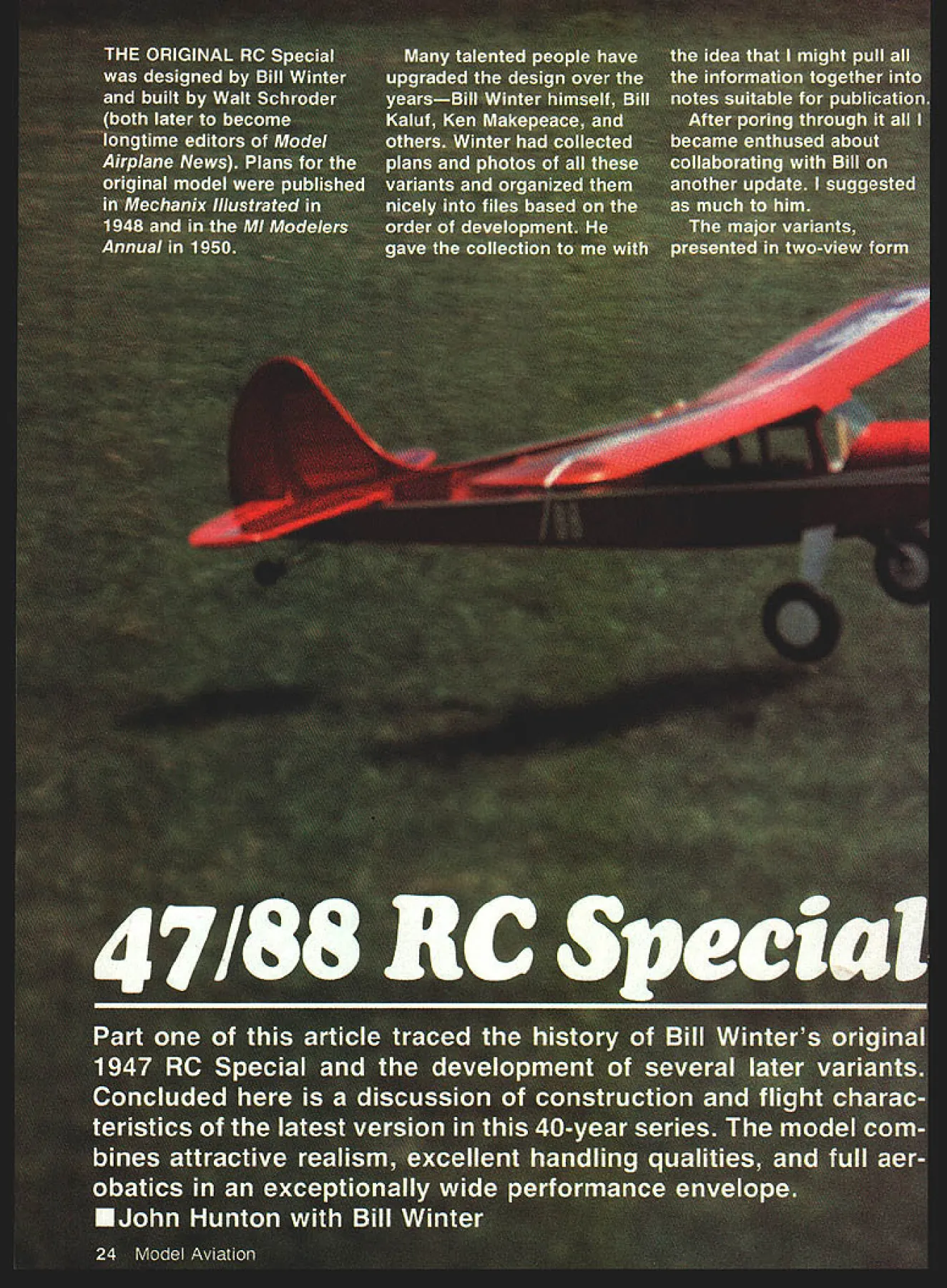
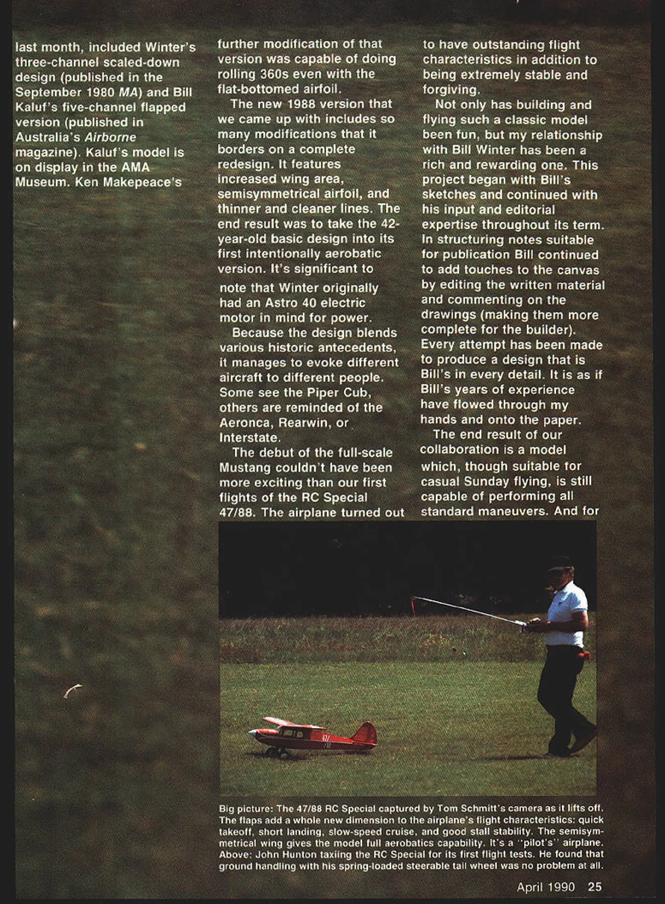
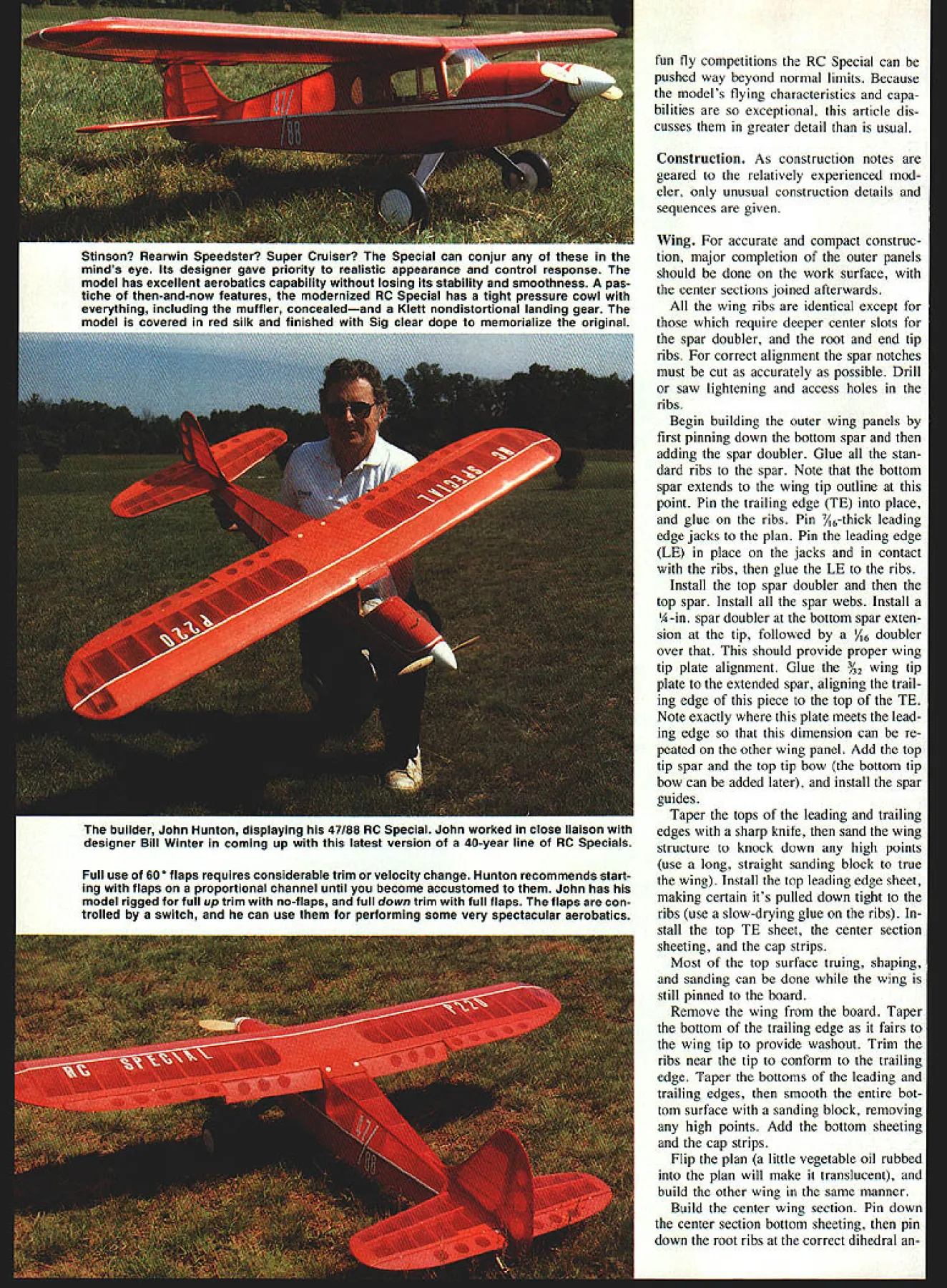
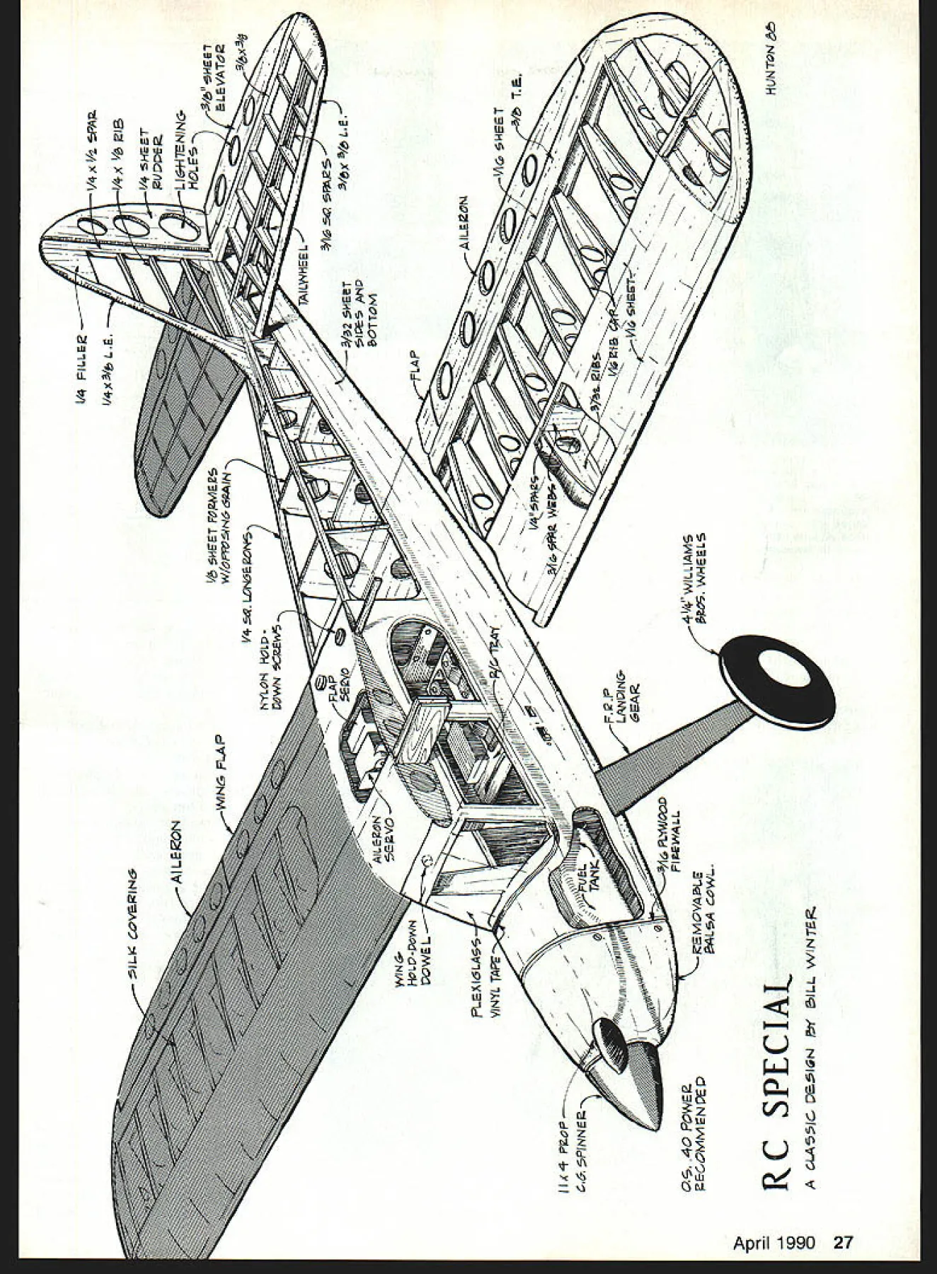
NO OCR TEXT NO OCR TEXT Stinson Rearwin Speedster Super Cruiser Special can conjur minds eye Its designer gave priority realistic appearance control response model has excellent aerobatics capability losing its stability smoothness pas tiche then-and-now features modernized RC Special has tight pressure cowl everything including muffler concealedand Klett nondistortional landing gear model covered red silk finished Sia clear doDe memorialize orloinal builder John Hunton displaying 47/88 RC Special John worked close liaison designer Bill Winter coming up latest version 40-year line RC Specials Full use 50 flaps requires considerable trim velocity change Hunton recommends start ing flaps proportional channel until become accustomed John has model rigged full up trim no-flaps full down trim full flaps flaps con trolled switch can use performing some very spectacular aerobatics fun fly competitions RC Special can pushed way beyond normal limits Because models flying characteristics capa bilities exceptional article dis cusses greater detail usual Construction As construction notes geared relatively experienced mod eler unusual construction details sequences given Wing accurate compact construc tion major completion outer panels should done work surface center sections joined afterwards wing ribs identical except require deeper center slots spar doubler root end tip ribs correct alignment spar notches must cut accurately possible Drill saw lightening access holes ribs Begin building outer wing panels first pinning down bottom spar adding spar doubler Glue stan dard ribs spar Note bottom spar extends wing tip outline point Pin trailing edge TE place glue ribs Pin 3/6-thick leading edge jacks plan Pin leading edge LE place jacks contact ribs glue LE ribs Install top spar doubler top spar Install spar webs Install A-in spar doubler bottom spar exten sion tip followed A6 doubler over should provide proper wing tip plate alignment Glue %2 wing tip plate extended spar aligning trail ing edge piece top TE Note exactly plate meets lead ing edge dimension can re peated other wing panel Add top tip spar top tip bow bottom tip bow can added later install spar guides Taper tops leading trailing edges sharp knife sand wing structure knock down high points use long straight sanding block true wing Install top leading edge sheet making certain its pulled down tight ribs use slow-drying glue ribs stall top TE sheet center section sheeting cap strips Most top surface truing shaping sanding can done wing still pinned board Remove wing board Taper bottom trailing edge fairs wing tip provide washout Trim ribs near tip conform edge Taper bottoms leading a,u trailing edges smooth entire bot tom surface sanding block removing high points Add bottom sheeting cap strips Flip plan little vegetable oil rubbea plan will make translucent build other wing same manner Build center wing section Pin down center section bottom sheeting pin down root ribs correct dihedral 1/4 PiLL& /4X3/bLE / SHEET FM& IN-N / NYLON 8OL-2 POWN I I /4 5HET LI*TENIN& t1LE- 3/s H7 TO C6 PINNE 4 PowEa MMNVE WIN HO-PCWN PQW&L I/rZZz LE4I6LASS VINYL TAP 7ALA COWL kTAILWHEEL -7-3/2HET 7 7CTTOM VIcHEET I/42PA$1 SEAR -7 -7 41/4P WILLIAMS o WHEELS RC SPECIAL CAAS5IC ~IQtJ Pi ILL WINTER AILEON TON Install other center section parts including main spar trailing edge doublers install top sheeting yet Make blocks prop up wing tips proper dihedral angle Prefit wing panel pinned-down center section Liberally apply slow-drying glue dou blers butt joints slip wing panels place Let assembly dry thor oughly before completing center section sheeting faceted horizontal stabilizer can ac curately easily assembled pinning down lower spar tapering bot tom surface trailing edge pinning place entire stabilizer can built basic assembly leading edge will floating above board should present no problem faceted sembly easy block sand final shape Its strong provides something lift ing surface improves models handling fin straightforward built right over plans Fuselage assembly begins building ~1 JUP COlA CT PROCrFtt 11 MLM OCCW -- -ItOT&97 -i--i M,7RAOl / / 44-CFAYUF 44 SWEET FzCeCOCC*COW p41 CAM 1011 4 FLIt. TMAC 4110 Aa IA WIFE oVEIIM4AM $11 COWL MLOCMR 4A4AIWA RCTTAO FRONT 41644 OF 0 FIATFLAT 4104 MOwS6 AWE two sheet sides Note manner front edges two sides trimmed determines engine alignment Building slight amount down right thrust improves flight characteristics considerably Cut 1R-in balsa formers shape care fully noting direction grain glue pieces together Assemble form ers fuselage sides over plan sure correct alignment Cut out install two plywood formers Drill firewall engine mounts install blind nuts cabin area should four inches across %2 sheet balsa false front fuselage bottom provides good fuselage alignment before adding bottom fuselage fairing blocks Assem ble bottom fuselage parts Provide cutout plywood landing gear mount Drill landing gear mount match gear install blind nuts mount stall top longerons Control surfaces flaps Center hinges used exception ailerons flaps ailerons top hinged good upper surface continuity close fit flaps bottom hinged good air flow across top well tight fit Engine installation cowling An verted engine installation shown plans open duct cooling OS muffler fairs well fuselage complication youll encounter difficulty getting cowl off 28 Model Aviation hap aileron control servos shown neatly mounted close together bottom center wing panel Note peg leading edge two holes nylon screws trailing edge used securing wing fuselage neat functional servo receiver stallation servos mounted ply wood tray screwed hardwood blocks fuselage sides receiver mounted antivibration pad se cured foam-backed straps piece tape attached back fuel tank used remove tank necessary authors unique engine baffle muffler system designed built cowl Note aluminum foil between muffler firewall help dissipate heat enclosed system Hunton fashioned parts commonly available aluminum stock Full-Size Plans AvailableSee Page 196 FA StOWS A--A A%APLYACDC MOVAMSNT F WAAMAC I1 IAAAFO AF SWAAA VA C itsA AC#4N1 ACTS COAN COACOJS CCCWN 0450 tATtOO WOWAAS Cr010 OFCAASCWA COCALVA ACTATTACC SCCAWA SALCCATN FOAM TA r FOCI FFAMA AC 5610thF 05 -OCCT OF-r PtA AC SOAAF 0CrF &AW MCSAflM RC SPECIAL WLLAM J WNThS-- 0TAOP5 PCOCO ASiAOIFSACOS LAOS OCAWN AT CFN FAJN7FAh/bAPT4T0 1 round muffler needle valve needle valve youll need deep cket fit needle valve hex modify ne two-flat version tool can otched Carborundum wheel remel tool clear needle valve pring way needle valve can asily removed facilitate cowl removal muffler either provide access oles muffler removal notch out owl rear will slip over uffler extension ressure cowl alternative An alternate owl used prototype shown lans Its pressure cowl installation ie muffler concealed Though its great eal trouble build system con idered authentic installation ince older engines didnt have mufflers ianging out side Its also very clean erodynamically see section flying ie model cowl utilizes pressure differential etween air intake outlet move ir across engine Baffle plates pro ided engine cooling area order duce cross section increase air ye city over engine cooling fins pressure cowl works very well ou smell something after initial lights remember muffler inside ne cowl does get hot helps over painted surfaces near muffler luminum foil reflect heat transfer tube muffler built ccupy space behind engine rather extend outside cowl de tailed plans case wish go extra trouble building hoped OS 40 new exhaust system would have nearly much power original assembly Sur prisingly tests proved OS 40 ac tually performed few hundred rpm better stock muffler Also engine seems quieter new system Covering silk tedious result can really worth especially clear finish used covering method used prototype follows 1 Use nitrate clear dope thinned 50/50 coat framework least three coats 2 Cut silk large panel prac tical eg wing panels horizontal stabi lizer piece continuous around leading edge grain silk spanwise surfaces lengthwise fuselage 3 Wet silk keep wet until last edge doped keep spray bottle handy 4 Begin edge pin silk down 5 Stretch silk across middle surface pin down Work out both directions April 1990 29 ne steeraoie tall wneei auacnea ruaaer via DelicranK conirum ruu aiu hum Springs incorporated system absorb shock reduce stress servo stretching pinning down go 7 time get edge pinned tight dope down 8 Overlap edges stretch ing silk fingers 9 Use very thin clear nitrate first coats until silk sealed Suggestion Dope sur face upside down 10 After sealing silk nitrate allowing set com pletely go butyrate clear dope nitrate isnt fuel-proof final three coats doping use retarder can prevent blushing humid conditions Fine-grain silk available Model wing ai ack th fly 30 Model Aviation Covering Co 2320 Ocean Parkway Brooklyn NY 11223 Flying Since Im accustomed fly ing sport model high-performance first flights 47/88 surprise notes maiden flight should prepare what expect photo session first flight seemed very long time big test finally came Bill Winter course several other prominent terested modelers Special taxied straight ahead being Jut start found model reli rCh w iad eate d him oe no puffy tr sky e Bill netric cial c iL rith s iow 1 wat ding lflpL*OOL OLALL tISS 34z S&LA UNLSSS NCThO 00 1 _ 0 __ 0 0 __ 0___ 0___ NaIL TAFSLT& A7L A5AALH riiIIii POVrAS NASOU R C 5CIAL PATE 2 /M very responsive rudder left ground its own accord after rather short takeoff run lifted nose fairly steep climb attitude get some altitude safely un der model readily apparent new Special high rate climb wasliterallyin its element ill hai d lift agai Qua landed ierfuI d ower ide d Bill Winters Airtroncs MD7SP seven-channel radio specifically designed Sailpianing example todays super radios allow elevator/flap flap/elevator mixing features could greatly enhance flight characteristics inherent 47/88 RC Special Full-Size Plans Available Page 196 /10 ATON 140 0 0 ..NPIONNU 4 0055 00/04 SON ThAI 4 ONPOLON flN.~OCPYYWOOO NO/ION tALC 005. Vi SNWON TONYrolaNd WING PAP - NO \ /0550 45/4100 ONSLI 00 OPTIC NOMINAL tWINS OF A.NOON N ANtON-WAY YPLANIOO PN*0t POLO GOON OIFPNOLNflAL NOTION GAINON - YIN NLNA rO Pan F ANIONS 042L CA 0O1% SWAN TOP ro 7-YN TO CNRON IN ON/SNN IIIONN[I IO -S/NC NNNA WINO SINS .fl 0P05 NOON SO SAUNANONTINCO 700 ONO WTCOM010 OrONO NFNfl 75 TIP fl A NP t7TM FNN 000 SOSNOTN OPOINTjNNNNNGIN 54NI N P OINOONINSFNRPNPOPNNO VON COlON NA TOP**OTOIA WN~N .NAON& NN0N C SO/GO NIL/St ---0/word NOINflO CONOINA BOA N-IC ANNONN --SFPON C-I-4I C5-004SL 37 012 SONVSLONOL 3 j5 3~j~P~/Oo2 Trim changes well within range [his seemed amazing since model new airfoil incidence model seemed rock-solid stable urns moving through air very ast covering lot sky Some low passes made photo raphic purposes going around runs engine flamed out problem plagued us day until low plug changed reliable Fox lug set up normal dead-stick land ng model coming down hould have put flaps down laps on/off switch time [forced model over threshold much too fast too high seemed little choice e 1800 turn land downwind model have enough airspeed make turn racked around tight turn thought advisable plenty speed left downwind landing no problem discussing first flight con cluded RC Special very clean aerodynamically Later flights confirmed engine fully cowled no muffler hanging breeze model has very shallow glide angle unless its slowed way down lot fun first flight day Don Srull noted Northern Virginia mod eler MA author flew new RC Spe cial did Bernie Stuecker photogra pher article Bill Winter him self Bill very content fly model loose circles figure eights can probably tell about model doing simple maneuvers can us doing pattern Bill suggested minor incidence change has imple mented plans test model following notes RC Specials flight characteristics may help first flights Takeoff model tail-dragger Stay rudder through takeoff climbout Use aileron keep wings level Climbout can climb very steep gle fact can loop soon after wheels leave ground would prob ably better restrict climb under 300 maintain good engine cooling airflow April 1990 31 01t&NNN OOIL POt LOX NYLON NCtSWN - TV SAL NI o --- 4LNNIN0 OOOYr2 AL WING FLAP I/Nj ALNA Cr 1 1/2 N LNO NIINENNA AC/NOON ~LI4flOOC LNOX INOLIN50T 5 O 4 IIO500NTA/ SPAPLLINN tINS ONN 5000 Flight characteristics inLeft Forty-one years after flying first RC Special Bill Winter attended John Hunton left Don Srull seems awed speed smooth flight latest ver sion Above John Huntons biplane version flies flaps half down lower wings chord span % top wing can removed two minutes Bill Winter first editor MA its present magazine form back 1975 holds John Huntons latest version lust prior its first test flight its first flight flew effortlessly requiring little no adjustment Pressure Cowl Concealed Installation As photographs show builder designed used true pressure cowl order eliminate protuberances nose totally concealed installation rare As part tight cowl design Hunton created own compact muffler square tubing found hardware emporium OS 40 engine turned 300 rpm faster stock installation features superior performance its clean lines properly engineered baffles controlling airflow over around engine Bill Winter sug gested plans show normal engine/muffler installation pressure cowl details grouped separately benefit builders required expertise An OS 40 engine installed Sig metal mounts John Huntons custom muffler nes tles behind side exhaust engine baf fles increase air flow over cooling fins fin-and-rudder assembly ready cover ing hinging fin incorporates tabs fit through stabilizer lock rigidly place open structure light yet strong soft sheet rudder has hard bal sa leading edge glued firm hinging aileron top both flaps ready covering flap center shows slots cut out full-scale-type Robart hinges other flap shows curved upper sur face Both ailerons flaps have antiwarp end caps lightening holes can easily cut out sharpened thin-walled tubing PLY0lYe tId floe It00M0II P OW 6dec10 N YP 0081dM FM 0 YM engine mounts upside-down mod ci exhaust exits through bot tom V-shaped opening baffle al lows cooling air muffler area transfer duct connecting engine exhaust port muffler visible photo photo shows pressure vent tube connection muffler muffler components assembled machine screws joints sealed RTV Hear view engine/muffler assembly balsa cowling transfer duct left muffler proved very quiet actually resulted higher engine rpm carved balsa tight-fit cowl viewed rear shot shows blocks m tions plan provide thin walls witn equate strength cowl commodo OS 40 engine Sig John Huntons home-brew cowl can modified necessary r ber optional engine/muffler installatioi 32 Model Aviation Full-Size Plans Available Paqe 196 OSILL TO 011 55861F10 Xis PLYLANWS5 GEAR aLBIT * asia ONES ON IBOTO Wa 509 INSTALL S.sNA 5 5A~A A -pM PAaa5 P91 Sad &5AA WY CS Ut ON W5WLSJ5 ALL FOtMEP5 Ms BALSA AMLSS Natas sra5pW5a 0 0 PLYAaOOP pAaTS Sa PRILL PSa 4OsW5t F25N M*N BPAR 05LpIPA 0 RSO IE p5tULPS / SPECrAL PLATE 91 a OPASLID 5585 asp 5 WEB 5588 aPp D jOI neat trick sheeting tops D-tubes ensures continuous contact ribs Use slow-drying glue install sheeting operation Insert pins rib leading edge spar stretch rubberbands between pair will exert pressure across rib face sure use easy-bend medium balsa sheeting Landing area significant dif ference sport model RC Special very slippery clean airplane out flaps angle glide very shallow makes difficult get model down youre flying restricted area sure engine capable very slow idle Use flaps feel confident will best establish pitch trim position flaps-on flaps-off can use flaps will flapson can fly model very slowly out fear stalling thus attain good Left structurally complete right wing clearly shows high-quality wood used throughout D-tube generous top bottom spars aileron spar cap strips make rigid strong wing Note contoured wing tips triangular piece closes flap gap p0 sitions Right faceted stabilizer elevator assemblies stabilizer has thick cross-section upper lower main spars its very strong across middle leading edge elevators joined -in dowel horn located left elevator herently stable model have ever flown its overly stable its definitely twitchy Yet RC Special can turned dime looped tightly flown edge stall concern flaps down model will seem hover sky flaps later changed on/off proportional channel worked great Using flaps introduces pitch changes Trim rectified flaps model flown very slowly will best become familiar flaps good altitude can used reliably landing rate descent precise control can achieved radios capable mix ing flaps elevator trim As notes being written also flying RC Special quite lot Ive amazed find addition its ex cellent flight characteristics plane has April 1990 33 completed 47/88 RC Special its bare bones Though parts count higher kit model far less compli cated looks Construction straight forward except pressure cowling optional wide choice engine stallations feasible standard cowl model has very clean aerody namic lines Note upper fuselage longerons fair neatly fin structure partially completed fuselage showing cowling under construction around tire temporarily installed engine top piece fitted between firewall spinner supported balsa blocks side piece behind engine place blocks glued together cowling carved sanded fuselage contour very wide flight envelope choose push model youll find everything top end outstandingits fast has excellent rate angle climb good roll rate its bottom end flight envelope offers con trast flaps down will take off just few feet turn dime hover land want land Bill Winter has designed classic-looking honest-flying airplane RC Special has kind broad-spectrum perform ance will keep happy years come 34 Model Aviation designer Bill Winter right looks 1 ne neariy compietea Dasic ruseiage struc ture cabin sides window areas builder John Hunton checks over nearly plywood lower full-length sides completed wing structure John took great medium-grade balsa sheet two-piece pains ensure Bill Winters design con- rear bulkheads overlap slightly upper cepts carried through entire model except Johns optional pressure cowl ing vertical-grained lower horizontal grained structure lightweight yet very strong Note four tapped pine cowl mounting blocks attached firewall
Edition: Model Aviation - 1990/04
Page Numbers: 24, 25, 26, 27, 28, 29, 30, 31, 32, 33, 34
Edition: Model Aviation - 1990/04
Page Numbers: 24, 25, 26, 27, 28, 29, 30, 31, 32, 33, 34
NO OCR TEXT NO OCR TEXT Stinson Rearwin Speedster Super Cruiser Special can conjur minds eye Its designer gave priority realistic appearance control response model has excellent aerobatics capability losing its stability smoothness pas tiche then-and-now features modernized RC Special has tight pressure cowl everything including muffler concealedand Klett nondistortional landing gear model covered red silk finished Sia clear doDe memorialize orloinal builder John Hunton displaying 47/88 RC Special John worked close liaison designer Bill Winter coming up latest version 40-year line RC Specials Full use 50 flaps requires considerable trim velocity change Hunton recommends start ing flaps proportional channel until become accustomed John has model rigged full up trim no-flaps full down trim full flaps flaps con trolled switch can use performing some very spectacular aerobatics fun fly competitions RC Special can pushed way beyond normal limits Because models flying characteristics capa bilities exceptional article dis cusses greater detail usual Construction As construction notes geared relatively experienced mod eler unusual construction details sequences given Wing accurate compact construc tion major completion outer panels should done work surface center sections joined afterwards wing ribs identical except require deeper center slots spar doubler root end tip ribs correct alignment spar notches must cut accurately possible Drill saw lightening access holes ribs Begin building outer wing panels first pinning down bottom spar adding spar doubler Glue stan dard ribs spar Note bottom spar extends wing tip outline point Pin trailing edge TE place glue ribs Pin 3/6-thick leading edge jacks plan Pin leading edge LE place jacks contact ribs glue LE ribs Install top spar doubler top spar Install spar webs Install A-in spar doubler bottom spar exten sion tip followed A6 doubler over should provide proper wing tip plate alignment Glue %2 wing tip plate extended spar aligning trail ing edge piece top TE Note exactly plate meets lead ing edge dimension can re peated other wing panel Add top tip spar top tip bow bottom tip bow can added later install spar guides Taper tops leading trailing edges sharp knife sand wing structure knock down high points use long straight sanding block true wing Install top leading edge sheet making certain its pulled down tight ribs use slow-drying glue ribs stall top TE sheet center section sheeting cap strips Most top surface truing shaping sanding can done wing still pinned board Remove wing board Taper bottom trailing edge fairs wing tip provide washout Trim ribs near tip conform edge Taper bottoms leading a,u trailing edges smooth entire bot tom surface sanding block removing high points Add bottom sheeting cap strips Flip plan little vegetable oil rubbea plan will make translucent build other wing same manner Build center wing section Pin down center section bottom sheeting pin down root ribs correct dihedral 1/4 PiLL& /4X3/bLE / SHEET FM& IN-N / NYLON 8OL-2 POWN I I /4 5HET LI*TENIN& t1LE- 3/s H7 TO C6 PINNE 4 PowEa MMNVE WIN HO-PCWN PQW&L I/rZZz LE4I6LASS VINYL TAP 7ALA COWL kTAILWHEEL -7-3/2HET 7 7CTTOM VIcHEET I/42PA$1 SEAR -7 -7 41/4P WILLIAMS o WHEELS RC SPECIAL CAAS5IC ~IQtJ Pi ILL WINTER AILEON TON Install other center section parts including main spar trailing edge doublers install top sheeting yet Make blocks prop up wing tips proper dihedral angle Prefit wing panel pinned-down center section Liberally apply slow-drying glue dou blers butt joints slip wing panels place Let assembly dry thor oughly before completing center section sheeting faceted horizontal stabilizer can ac curately easily assembled pinning down lower spar tapering bot tom surface trailing edge pinning place entire stabilizer can built basic assembly leading edge will floating above board should present no problem faceted sembly easy block sand final shape Its strong provides something lift ing surface improves models handling fin straightforward built right over plans Fuselage assembly begins building ~1 JUP COlA CT PROCrFtt 11 MLM OCCW -- -ItOT&97 -i--i M,7RAOl / / 44-CFAYUF 44 SWEET FzCeCOCC*COW p41 CAM 1011 4 FLIt. TMAC 4110 Aa IA WIFE oVEIIM4AM $11 COWL MLOCMR 4A4AIWA RCTTAO FRONT 41644 OF 0 FIATFLAT 4104 MOwS6 AWE two sheet sides Note manner front edges two sides trimmed determines engine alignment Building slight amount down right thrust improves flight characteristics considerably Cut 1R-in balsa formers shape care fully noting direction grain glue pieces together Assemble form ers fuselage sides over plan sure correct alignment Cut out install two plywood formers Drill firewall engine mounts install blind nuts cabin area should four inches across %2 sheet balsa false front fuselage bottom provides good fuselage alignment before adding bottom fuselage fairing blocks Assem ble bottom fuselage parts Provide cutout plywood landing gear mount Drill landing gear mount match gear install blind nuts mount stall top longerons Control surfaces flaps Center hinges used exception ailerons flaps ailerons top hinged good upper surface continuity close fit flaps bottom hinged good air flow across top well tight fit Engine installation cowling An verted engine installation shown plans open duct cooling OS muffler fairs well fuselage complication youll encounter difficulty getting cowl off 28 Model Aviation hap aileron control servos shown neatly mounted close together bottom center wing panel Note peg leading edge two holes nylon screws trailing edge used securing wing fuselage neat functional servo receiver stallation servos mounted ply wood tray screwed hardwood blocks fuselage sides receiver mounted antivibration pad se cured foam-backed straps piece tape attached back fuel tank used remove tank necessary authors unique engine baffle muffler system designed built cowl Note aluminum foil between muffler firewall help dissipate heat enclosed system Hunton fashioned parts commonly available aluminum stock Full-Size Plans AvailableSee Page 196 FA StOWS A--A A%APLYACDC MOVAMSNT F WAAMAC I1 IAAAFO AF SWAAA VA C itsA AC#4N1 ACTS COAN COACOJS CCCWN 0450 tATtOO WOWAAS Cr010 OFCAASCWA COCALVA ACTATTACC SCCAWA SALCCATN FOAM TA r FOCI FFAMA AC 5610thF 05 -OCCT OF-r PtA AC SOAAF 0CrF &AW MCSAflM RC SPECIAL WLLAM J WNThS-- 0TAOP5 PCOCO ASiAOIFSACOS LAOS OCAWN AT CFN FAJN7FAh/bAPT4T0 1 round muffler needle valve needle valve youll need deep cket fit needle valve hex modify ne two-flat version tool can otched Carborundum wheel remel tool clear needle valve pring way needle valve can asily removed facilitate cowl removal muffler either provide access oles muffler removal notch out owl rear will slip over uffler extension ressure cowl alternative An alternate owl used prototype shown lans Its pressure cowl installation ie muffler concealed Though its great eal trouble build system con idered authentic installation ince older engines didnt have mufflers ianging out side Its also very clean erodynamically see section flying ie model cowl utilizes pressure differential etween air intake outlet move ir across engine Baffle plates pro ided engine cooling area order duce cross section increase air ye city over engine cooling fins pressure cowl works very well ou smell something after initial lights remember muffler inside ne cowl does get hot helps over painted surfaces near muffler luminum foil reflect heat transfer tube muffler built ccupy space behind engine rather extend outside cowl de tailed plans case wish go extra trouble building hoped OS 40 new exhaust system would have nearly much power original assembly Sur prisingly tests proved OS 40 ac tually performed few hundred rpm better stock muffler Also engine seems quieter new system Covering silk tedious result can really worth especially clear finish used covering method used prototype follows 1 Use nitrate clear dope thinned 50/50 coat framework least three coats 2 Cut silk large panel prac tical eg wing panels horizontal stabi lizer piece continuous around leading edge grain silk spanwise surfaces lengthwise fuselage 3 Wet silk keep wet until last edge doped keep spray bottle handy 4 Begin edge pin silk down 5 Stretch silk across middle surface pin down Work out both directions April 1990 29 ne steeraoie tall wneei auacnea ruaaer via DelicranK conirum ruu aiu hum Springs incorporated system absorb shock reduce stress servo stretching pinning down go 7 time get edge pinned tight dope down 8 Overlap edges stretch ing silk fingers 9 Use very thin clear nitrate first coats until silk sealed Suggestion Dope sur face upside down 10 After sealing silk nitrate allowing set com pletely go butyrate clear dope nitrate isnt fuel-proof final three coats doping use retarder can prevent blushing humid conditions Fine-grain silk available Model wing ai ack th fly 30 Model Aviation Covering Co 2320 Ocean Parkway Brooklyn NY 11223 Flying Since Im accustomed fly ing sport model high-performance first flights 47/88 surprise notes maiden flight should prepare what expect photo session first flight seemed very long time big test finally came Bill Winter course several other prominent terested modelers Special taxied straight ahead being Jut start found model reli rCh w iad eate d him oe no puffy tr sky e Bill netric cial c iL rith s iow 1 wat ding lflpL*OOL OLALL tISS 34z S&LA UNLSSS NCThO 00 1 _ 0 __ 0 0 __ 0___ 0___ NaIL TAFSLT& A7L A5AALH riiIIii POVrAS NASOU R C 5CIAL PATE 2 /M very responsive rudder left ground its own accord after rather short takeoff run lifted nose fairly steep climb attitude get some altitude safely un der model readily apparent new Special high rate climb wasliterallyin its element ill hai d lift agai Qua landed ierfuI d ower ide d Bill Winters Airtroncs MD7SP seven-channel radio specifically designed Sailpianing example todays super radios allow elevator/flap flap/elevator mixing features could greatly enhance flight characteristics inherent 47/88 RC Special Full-Size Plans Available Page 196 /10 ATON 140 0 0 ..NPIONNU 4 0055 00/04 SON ThAI 4 ONPOLON flN.~OCPYYWOOO NO/ION tALC 005. Vi SNWON TONYrolaNd WING PAP - NO \ /0550 45/4100 ONSLI 00 OPTIC NOMINAL tWINS OF A.NOON N ANtON-WAY YPLANIOO PN*0t POLO GOON OIFPNOLNflAL NOTION GAINON - YIN NLNA rO Pan F ANIONS 042L CA 0O1% SWAN TOP ro 7-YN TO CNRON IN ON/SNN IIIONN[I IO -S/NC NNNA WINO SINS .fl 0P05 NOON SO SAUNANONTINCO 700 ONO WTCOM010 OrONO NFNfl 75 TIP fl A NP t7TM FNN 000 SOSNOTN OPOINTjNNNNNGIN 54NI N P OINOONINSFNRPNPOPNNO VON COlON NA TOP**OTOIA WN~N .NAON& NN0N C SO/GO NIL/St ---0/word NOINflO CONOINA BOA N-IC ANNONN --SFPON C-I-4I C5-004SL 37 012 SONVSLONOL 3 j5 3~j~P~/Oo2 Trim changes well within range [his seemed amazing since model new airfoil incidence model seemed rock-solid stable urns moving through air very ast covering lot sky Some low passes made photo raphic purposes going around runs engine flamed out problem plagued us day until low plug changed reliable Fox lug set up normal dead-stick land ng model coming down hould have put flaps down laps on/off switch time [forced model over threshold much too fast too high seemed little choice e 1800 turn land downwind model have enough airspeed make turn racked around tight turn thought advisable plenty speed left downwind landing no problem discussing first flight con cluded RC Special very clean aerodynamically Later flights confirmed engine fully cowled no muffler hanging breeze model has very shallow glide angle unless its slowed way down lot fun first flight day Don Srull noted Northern Virginia mod eler MA author flew new RC Spe cial did Bernie Stuecker photogra pher article Bill Winter him self Bill very content fly model loose circles figure eights can probably tell about model doing simple maneuvers can us doing pattern Bill suggested minor incidence change has imple mented plans test model following notes RC Specials flight characteristics may help first flights Takeoff model tail-dragger Stay rudder through takeoff climbout Use aileron keep wings level Climbout can climb very steep gle fact can loop soon after wheels leave ground would prob ably better restrict climb under 300 maintain good engine cooling airflow April 1990 31 01t&NNN OOIL POt LOX NYLON NCtSWN - TV SAL NI o --- 4LNNIN0 OOOYr2 AL WING FLAP I/Nj ALNA Cr 1 1/2 N LNO NIINENNA AC/NOON ~LI4flOOC LNOX INOLIN50T 5 O 4 IIO500NTA/ SPAPLLINN tINS ONN 5000 Flight characteristics inLeft Forty-one years after flying first RC Special Bill Winter attended John Hunton left Don Srull seems awed speed smooth flight latest ver sion Above John Huntons biplane version flies flaps half down lower wings chord span % top wing can removed two minutes Bill Winter first editor MA its present magazine form back 1975 holds John Huntons latest version lust prior its first test flight its first flight flew effortlessly requiring little no adjustment Pressure Cowl Concealed Installation As photographs show builder designed used true pressure cowl order eliminate protuberances nose totally concealed installation rare As part tight cowl design Hunton created own compact muffler square tubing found hardware emporium OS 40 engine turned 300 rpm faster stock installation features superior performance its clean lines properly engineered baffles controlling airflow over around engine Bill Winter sug gested plans show normal engine/muffler installation pressure cowl details grouped separately benefit builders required expertise An OS 40 engine installed Sig metal mounts John Huntons custom muffler nes tles behind side exhaust engine baf fles increase air flow over cooling fins fin-and-rudder assembly ready cover ing hinging fin incorporates tabs fit through stabilizer lock rigidly place open structure light yet strong soft sheet rudder has hard bal sa leading edge glued firm hinging aileron top both flaps ready covering flap center shows slots cut out full-scale-type Robart hinges other flap shows curved upper sur face Both ailerons flaps have antiwarp end caps lightening holes can easily cut out sharpened thin-walled tubing PLY0lYe tId floe It00M0II P OW 6dec10 N YP 0081dM FM 0 YM engine mounts upside-down mod ci exhaust exits through bot tom V-shaped opening baffle al lows cooling air muffler area transfer duct connecting engine exhaust port muffler visible photo photo shows pressure vent tube connection muffler muffler components assembled machine screws joints sealed RTV Hear view engine/muffler assembly balsa cowling transfer duct left muffler proved very quiet actually resulted higher engine rpm carved balsa tight-fit cowl viewed rear shot shows blocks m tions plan provide thin walls witn equate strength cowl commodo OS 40 engine Sig John Huntons home-brew cowl can modified necessary r ber optional engine/muffler installatioi 32 Model Aviation Full-Size Plans Available Paqe 196 OSILL TO 011 55861F10 Xis PLYLANWS5 GEAR aLBIT * asia ONES ON IBOTO Wa 509 INSTALL S.sNA 5 5A~A A -pM PAaa5 P91 Sad &5AA WY CS Ut ON W5WLSJ5 ALL FOtMEP5 Ms BALSA AMLSS Natas sra5pW5a 0 0 PLYAaOOP pAaTS Sa PRILL PSa 4OsW5t F25N M*N BPAR 05LpIPA 0 RSO IE p5tULPS / SPECrAL PLATE 91 a OPASLID 5585 asp 5 WEB 5588 aPp D jOI neat trick sheeting tops D-tubes ensures continuous contact ribs Use slow-drying glue install sheeting operation Insert pins rib leading edge spar stretch rubberbands between pair will exert pressure across rib face sure use easy-bend medium balsa sheeting Landing area significant dif ference sport model RC Special very slippery clean airplane out flaps angle glide very shallow makes difficult get model down youre flying restricted area sure engine capable very slow idle Use flaps feel confident will best establish pitch trim position flaps-on flaps-off can use flaps will flapson can fly model very slowly out fear stalling thus attain good Left structurally complete right wing clearly shows high-quality wood used throughout D-tube generous top bottom spars aileron spar cap strips make rigid strong wing Note contoured wing tips triangular piece closes flap gap p0 sitions Right faceted stabilizer elevator assemblies stabilizer has thick cross-section upper lower main spars its very strong across middle leading edge elevators joined -in dowel horn located left elevator herently stable model have ever flown its overly stable its definitely twitchy Yet RC Special can turned dime looped tightly flown edge stall concern flaps down model will seem hover sky flaps later changed on/off proportional channel worked great Using flaps introduces pitch changes Trim rectified flaps model flown very slowly will best become familiar flaps good altitude can used reliably landing rate descent precise control can achieved radios capable mix ing flaps elevator trim As notes being written also flying RC Special quite lot Ive amazed find addition its ex cellent flight characteristics plane has April 1990 33 completed 47/88 RC Special its bare bones Though parts count higher kit model far less compli cated looks Construction straight forward except pressure cowling optional wide choice engine stallations feasible standard cowl model has very clean aerody namic lines Note upper fuselage longerons fair neatly fin structure partially completed fuselage showing cowling under construction around tire temporarily installed engine top piece fitted between firewall spinner supported balsa blocks side piece behind engine place blocks glued together cowling carved sanded fuselage contour very wide flight envelope choose push model youll find everything top end outstandingits fast has excellent rate angle climb good roll rate its bottom end flight envelope offers con trast flaps down will take off just few feet turn dime hover land want land Bill Winter has designed classic-looking honest-flying airplane RC Special has kind broad-spectrum perform ance will keep happy years come 34 Model Aviation designer Bill Winter right looks 1 ne neariy compietea Dasic ruseiage struc ture cabin sides window areas builder John Hunton checks over nearly plywood lower full-length sides completed wing structure John took great medium-grade balsa sheet two-piece pains ensure Bill Winters design con- rear bulkheads overlap slightly upper cepts carried through entire model except Johns optional pressure cowl ing vertical-grained lower horizontal grained structure lightweight yet very strong Note four tapped pine cowl mounting blocks attached firewall
Edition: Model Aviation - 1990/04
Page Numbers: 24, 25, 26, 27, 28, 29, 30, 31, 32, 33, 34
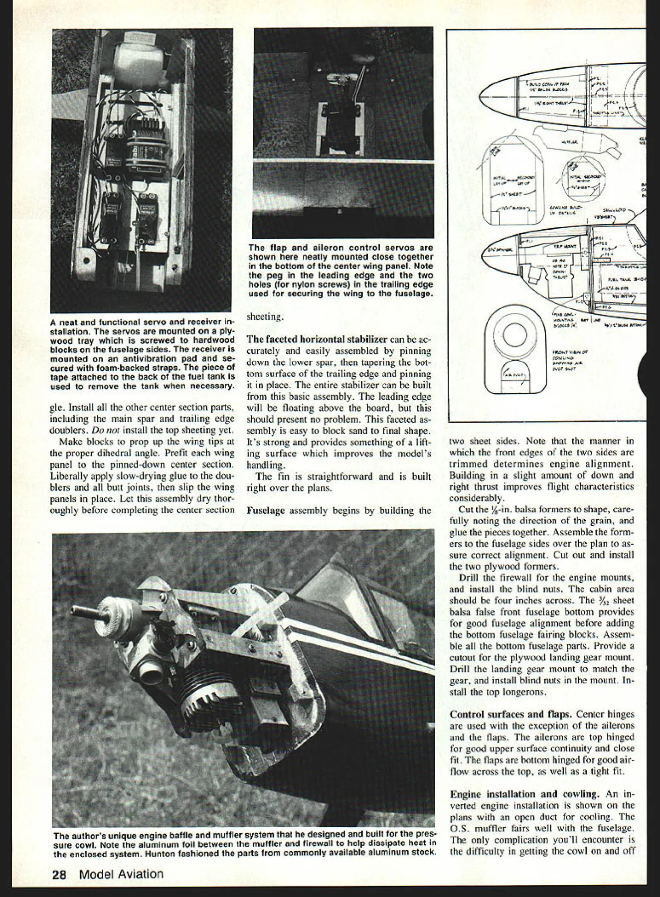
NO OCR TEXT NO OCR TEXT Stinson Rearwin Speedster Super Cruiser Special can conjur minds eye Its designer gave priority realistic appearance control response model has excellent aerobatics capability losing its stability smoothness pas tiche then-and-now features modernized RC Special has tight pressure cowl everything including muffler concealedand Klett nondistortional landing gear model covered red silk finished Sia clear doDe memorialize orloinal builder John Hunton displaying 47/88 RC Special John worked close liaison designer Bill Winter coming up latest version 40-year line RC Specials Full use 50 flaps requires considerable trim velocity change Hunton recommends start ing flaps proportional channel until become accustomed John has model rigged full up trim no-flaps full down trim full flaps flaps con trolled switch can use performing some very spectacular aerobatics fun fly competitions RC Special can pushed way beyond normal limits Because models flying characteristics capa bilities exceptional article dis cusses greater detail usual Construction As construction notes geared relatively experienced mod eler unusual construction details sequences given Wing accurate compact construc tion major completion outer panels should done work surface center sections joined afterwards wing ribs identical except require deeper center slots spar doubler root end tip ribs correct alignment spar notches must cut accurately possible Drill saw lightening access holes ribs Begin building outer wing panels first pinning down bottom spar adding spar doubler Glue stan dard ribs spar Note bottom spar extends wing tip outline point Pin trailing edge TE place glue ribs Pin 3/6-thick leading edge jacks plan Pin leading edge LE place jacks contact ribs glue LE ribs Install top spar doubler top spar Install spar webs Install A-in spar doubler bottom spar exten sion tip followed A6 doubler over should provide proper wing tip plate alignment Glue %2 wing tip plate extended spar aligning trail ing edge piece top TE Note exactly plate meets lead ing edge dimension can re peated other wing panel Add top tip spar top tip bow bottom tip bow can added later install spar guides Taper tops leading trailing edges sharp knife sand wing structure knock down high points use long straight sanding block true wing Install top leading edge sheet making certain its pulled down tight ribs use slow-drying glue ribs stall top TE sheet center section sheeting cap strips Most top surface truing shaping sanding can done wing still pinned board Remove wing board Taper bottom trailing edge fairs wing tip provide washout Trim ribs near tip conform edge Taper bottoms leading a,u trailing edges smooth entire bot tom surface sanding block removing high points Add bottom sheeting cap strips Flip plan little vegetable oil rubbea plan will make translucent build other wing same manner Build center wing section Pin down center section bottom sheeting pin down root ribs correct dihedral 1/4 PiLL& /4X3/bLE / SHEET FM& IN-N / NYLON 8OL-2 POWN I I /4 5HET LI*TENIN& t1LE- 3/s H7 TO C6 PINNE 4 PowEa MMNVE WIN HO-PCWN PQW&L I/rZZz LE4I6LASS VINYL TAP 7ALA COWL kTAILWHEEL -7-3/2HET 7 7CTTOM VIcHEET I/42PA$1 SEAR -7 -7 41/4P WILLIAMS o WHEELS RC SPECIAL CAAS5IC ~IQtJ Pi ILL WINTER AILEON TON Install other center section parts including main spar trailing edge doublers install top sheeting yet Make blocks prop up wing tips proper dihedral angle Prefit wing panel pinned-down center section Liberally apply slow-drying glue dou blers butt joints slip wing panels place Let assembly dry thor oughly before completing center section sheeting faceted horizontal stabilizer can ac curately easily assembled pinning down lower spar tapering bot tom surface trailing edge pinning place entire stabilizer can built basic assembly leading edge will floating above board should present no problem faceted sembly easy block sand final shape Its strong provides something lift ing surface improves models handling fin straightforward built right over plans Fuselage assembly begins building ~1 JUP COlA CT PROCrFtt 11 MLM OCCW -- -ItOT&97 -i--i M,7RAOl / / 44-CFAYUF 44 SWEET FzCeCOCC*COW p41 CAM 1011 4 FLIt. TMAC 4110 Aa IA WIFE oVEIIM4AM $11 COWL MLOCMR 4A4AIWA RCTTAO FRONT 41644 OF 0 FIATFLAT 4104 MOwS6 AWE two sheet sides Note manner front edges two sides trimmed determines engine alignment Building slight amount down right thrust improves flight characteristics considerably Cut 1R-in balsa formers shape care fully noting direction grain glue pieces together Assemble form ers fuselage sides over plan sure correct alignment Cut out install two plywood formers Drill firewall engine mounts install blind nuts cabin area should four inches across %2 sheet balsa false front fuselage bottom provides good fuselage alignment before adding bottom fuselage fairing blocks Assem ble bottom fuselage parts Provide cutout plywood landing gear mount Drill landing gear mount match gear install blind nuts mount stall top longerons Control surfaces flaps Center hinges used exception ailerons flaps ailerons top hinged good upper surface continuity close fit flaps bottom hinged good air flow across top well tight fit Engine installation cowling An verted engine installation shown plans open duct cooling OS muffler fairs well fuselage complication youll encounter difficulty getting cowl off 28 Model Aviation hap aileron control servos shown neatly mounted close together bottom center wing panel Note peg leading edge two holes nylon screws trailing edge used securing wing fuselage neat functional servo receiver stallation servos mounted ply wood tray screwed hardwood blocks fuselage sides receiver mounted antivibration pad se cured foam-backed straps piece tape attached back fuel tank used remove tank necessary authors unique engine baffle muffler system designed built cowl Note aluminum foil between muffler firewall help dissipate heat enclosed system Hunton fashioned parts commonly available aluminum stock Full-Size Plans AvailableSee Page 196 FA StOWS A--A A%APLYACDC MOVAMSNT F WAAMAC I1 IAAAFO AF SWAAA VA C itsA AC#4N1 ACTS COAN COACOJS CCCWN 0450 tATtOO WOWAAS Cr010 OFCAASCWA COCALVA ACTATTACC SCCAWA SALCCATN FOAM TA r FOCI FFAMA AC 5610thF 05 -OCCT OF-r PtA AC SOAAF 0CrF &AW MCSAflM RC SPECIAL WLLAM J WNThS-- 0TAOP5 PCOCO ASiAOIFSACOS LAOS OCAWN AT CFN FAJN7FAh/bAPT4T0 1 round muffler needle valve needle valve youll need deep cket fit needle valve hex modify ne two-flat version tool can otched Carborundum wheel remel tool clear needle valve pring way needle valve can asily removed facilitate cowl removal muffler either provide access oles muffler removal notch out owl rear will slip over uffler extension ressure cowl alternative An alternate owl used prototype shown lans Its pressure cowl installation ie muffler concealed Though its great eal trouble build system con idered authentic installation ince older engines didnt have mufflers ianging out side Its also very clean erodynamically see section flying ie model cowl utilizes pressure differential etween air intake outlet move ir across engine Baffle plates pro ided engine cooling area order duce cross section increase air ye city over engine cooling fins pressure cowl works very well ou smell something after initial lights remember muffler inside ne cowl does get hot helps over painted surfaces near muffler luminum foil reflect heat transfer tube muffler built ccupy space behind engine rather extend outside cowl de tailed plans case wish go extra trouble building hoped OS 40 new exhaust system would have nearly much power original assembly Sur prisingly tests proved OS 40 ac tually performed few hundred rpm better stock muffler Also engine seems quieter new system Covering silk tedious result can really worth especially clear finish used covering method used prototype follows 1 Use nitrate clear dope thinned 50/50 coat framework least three coats 2 Cut silk large panel prac tical eg wing panels horizontal stabi lizer piece continuous around leading edge grain silk spanwise surfaces lengthwise fuselage 3 Wet silk keep wet until last edge doped keep spray bottle handy 4 Begin edge pin silk down 5 Stretch silk across middle surface pin down Work out both directions April 1990 29 ne steeraoie tall wneei auacnea ruaaer via DelicranK conirum ruu aiu hum Springs incorporated system absorb shock reduce stress servo stretching pinning down go 7 time get edge pinned tight dope down 8 Overlap edges stretch ing silk fingers 9 Use very thin clear nitrate first coats until silk sealed Suggestion Dope sur face upside down 10 After sealing silk nitrate allowing set com pletely go butyrate clear dope nitrate isnt fuel-proof final three coats doping use retarder can prevent blushing humid conditions Fine-grain silk available Model wing ai ack th fly 30 Model Aviation Covering Co 2320 Ocean Parkway Brooklyn NY 11223 Flying Since Im accustomed fly ing sport model high-performance first flights 47/88 surprise notes maiden flight should prepare what expect photo session first flight seemed very long time big test finally came Bill Winter course several other prominent terested modelers Special taxied straight ahead being Jut start found model reli rCh w iad eate d him oe no puffy tr sky e Bill netric cial c iL rith s iow 1 wat ding lflpL*OOL OLALL tISS 34z S&LA UNLSSS NCThO 00 1 _ 0 __ 0 0 __ 0___ 0___ NaIL TAFSLT& A7L A5AALH riiIIii POVrAS NASOU R C 5CIAL PATE 2 /M very responsive rudder left ground its own accord after rather short takeoff run lifted nose fairly steep climb attitude get some altitude safely un der model readily apparent new Special high rate climb wasliterallyin its element ill hai d lift agai Qua landed ierfuI d ower ide d Bill Winters Airtroncs MD7SP seven-channel radio specifically designed Sailpianing example todays super radios allow elevator/flap flap/elevator mixing features could greatly enhance flight characteristics inherent 47/88 RC Special Full-Size Plans Available Page 196 /10 ATON 140 0 0 ..NPIONNU 4 0055 00/04 SON ThAI 4 ONPOLON flN.~OCPYYWOOO NO/ION tALC 005. Vi SNWON TONYrolaNd WING PAP - NO \ /0550 45/4100 ONSLI 00 OPTIC NOMINAL tWINS OF A.NOON N ANtON-WAY YPLANIOO PN*0t POLO GOON OIFPNOLNflAL NOTION GAINON - YIN NLNA rO Pan F ANIONS 042L CA 0O1% SWAN TOP ro 7-YN TO CNRON IN ON/SNN IIIONN[I IO -S/NC NNNA WINO SINS .fl 0P05 NOON SO SAUNANONTINCO 700 ONO WTCOM010 OrONO NFNfl 75 TIP fl A NP t7TM FNN 000 SOSNOTN OPOINTjNNNNNGIN 54NI N P OINOONINSFNRPNPOPNNO VON COlON NA TOP**OTOIA WN~N .NAON& NN0N C SO/GO NIL/St ---0/word NOINflO CONOINA BOA N-IC ANNONN --SFPON C-I-4I C5-004SL 37 012 SONVSLONOL 3 j5 3~j~P~/Oo2 Trim changes well within range [his seemed amazing since model new airfoil incidence model seemed rock-solid stable urns moving through air very ast covering lot sky Some low passes made photo raphic purposes going around runs engine flamed out problem plagued us day until low plug changed reliable Fox lug set up normal dead-stick land ng model coming down hould have put flaps down laps on/off switch time [forced model over threshold much too fast too high seemed little choice e 1800 turn land downwind model have enough airspeed make turn racked around tight turn thought advisable plenty speed left downwind landing no problem discussing first flight con cluded RC Special very clean aerodynamically Later flights confirmed engine fully cowled no muffler hanging breeze model has very shallow glide angle unless its slowed way down lot fun first flight day Don Srull noted Northern Virginia mod eler MA author flew new RC Spe cial did Bernie Stuecker photogra pher article Bill Winter him self Bill very content fly model loose circles figure eights can probably tell about model doing simple maneuvers can us doing pattern Bill suggested minor incidence change has imple mented plans test model following notes RC Specials flight characteristics may help first flights Takeoff model tail-dragger Stay rudder through takeoff climbout Use aileron keep wings level Climbout can climb very steep gle fact can loop soon after wheels leave ground would prob ably better restrict climb under 300 maintain good engine cooling airflow April 1990 31 01t&NNN OOIL POt LOX NYLON NCtSWN - TV SAL NI o --- 4LNNIN0 OOOYr2 AL WING FLAP I/Nj ALNA Cr 1 1/2 N LNO NIINENNA AC/NOON ~LI4flOOC LNOX INOLIN50T 5 O 4 IIO500NTA/ SPAPLLINN tINS ONN 5000 Flight characteristics inLeft Forty-one years after flying first RC Special Bill Winter attended John Hunton left Don Srull seems awed speed smooth flight latest ver sion Above John Huntons biplane version flies flaps half down lower wings chord span % top wing can removed two minutes Bill Winter first editor MA its present magazine form back 1975 holds John Huntons latest version lust prior its first test flight its first flight flew effortlessly requiring little no adjustment Pressure Cowl Concealed Installation As photographs show builder designed used true pressure cowl order eliminate protuberances nose totally concealed installation rare As part tight cowl design Hunton created own compact muffler square tubing found hardware emporium OS 40 engine turned 300 rpm faster stock installation features superior performance its clean lines properly engineered baffles controlling airflow over around engine Bill Winter sug gested plans show normal engine/muffler installation pressure cowl details grouped separately benefit builders required expertise An OS 40 engine installed Sig metal mounts John Huntons custom muffler nes tles behind side exhaust engine baf fles increase air flow over cooling fins fin-and-rudder assembly ready cover ing hinging fin incorporates tabs fit through stabilizer lock rigidly place open structure light yet strong soft sheet rudder has hard bal sa leading edge glued firm hinging aileron top both flaps ready covering flap center shows slots cut out full-scale-type Robart hinges other flap shows curved upper sur face Both ailerons flaps have antiwarp end caps lightening holes can easily cut out sharpened thin-walled tubing PLY0lYe tId floe It00M0II P OW 6dec10 N YP 0081dM FM 0 YM engine mounts upside-down mod ci exhaust exits through bot tom V-shaped opening baffle al lows cooling air muffler area transfer duct connecting engine exhaust port muffler visible photo photo shows pressure vent tube connection muffler muffler components assembled machine screws joints sealed RTV Hear view engine/muffler assembly balsa cowling transfer duct left muffler proved very quiet actually resulted higher engine rpm carved balsa tight-fit cowl viewed rear shot shows blocks m tions plan provide thin walls witn equate strength cowl commodo OS 40 engine Sig John Huntons home-brew cowl can modified necessary r ber optional engine/muffler installatioi 32 Model Aviation Full-Size Plans Available Paqe 196 OSILL TO 011 55861F10 Xis PLYLANWS5 GEAR aLBIT * asia ONES ON IBOTO Wa 509 INSTALL S.sNA 5 5A~A A -pM PAaa5 P91 Sad &5AA WY CS Ut ON W5WLSJ5 ALL FOtMEP5 Ms BALSA AMLSS Natas sra5pW5a 0 0 PLYAaOOP pAaTS Sa PRILL PSa 4OsW5t F25N M*N BPAR 05LpIPA 0 RSO IE p5tULPS / SPECrAL PLATE 91 a OPASLID 5585 asp 5 WEB 5588 aPp D jOI neat trick sheeting tops D-tubes ensures continuous contact ribs Use slow-drying glue install sheeting operation Insert pins rib leading edge spar stretch rubberbands between pair will exert pressure across rib face sure use easy-bend medium balsa sheeting Landing area significant dif ference sport model RC Special very slippery clean airplane out flaps angle glide very shallow makes difficult get model down youre flying restricted area sure engine capable very slow idle Use flaps feel confident will best establish pitch trim position flaps-on flaps-off can use flaps will flapson can fly model very slowly out fear stalling thus attain good Left structurally complete right wing clearly shows high-quality wood used throughout D-tube generous top bottom spars aileron spar cap strips make rigid strong wing Note contoured wing tips triangular piece closes flap gap p0 sitions Right faceted stabilizer elevator assemblies stabilizer has thick cross-section upper lower main spars its very strong across middle leading edge elevators joined -in dowel horn located left elevator herently stable model have ever flown its overly stable its definitely twitchy Yet RC Special can turned dime looped tightly flown edge stall concern flaps down model will seem hover sky flaps later changed on/off proportional channel worked great Using flaps introduces pitch changes Trim rectified flaps model flown very slowly will best become familiar flaps good altitude can used reliably landing rate descent precise control can achieved radios capable mix ing flaps elevator trim As notes being written also flying RC Special quite lot Ive amazed find addition its ex cellent flight characteristics plane has April 1990 33 completed 47/88 RC Special its bare bones Though parts count higher kit model far less compli cated looks Construction straight forward except pressure cowling optional wide choice engine stallations feasible standard cowl model has very clean aerody namic lines Note upper fuselage longerons fair neatly fin structure partially completed fuselage showing cowling under construction around tire temporarily installed engine top piece fitted between firewall spinner supported balsa blocks side piece behind engine place blocks glued together cowling carved sanded fuselage contour very wide flight envelope choose push model youll find everything top end outstandingits fast has excellent rate angle climb good roll rate its bottom end flight envelope offers con trast flaps down will take off just few feet turn dime hover land want land Bill Winter has designed classic-looking honest-flying airplane RC Special has kind broad-spectrum perform ance will keep happy years come 34 Model Aviation designer Bill Winter right looks 1 ne neariy compietea Dasic ruseiage struc ture cabin sides window areas builder John Hunton checks over nearly plywood lower full-length sides completed wing structure John took great medium-grade balsa sheet two-piece pains ensure Bill Winters design con- rear bulkheads overlap slightly upper cepts carried through entire model except Johns optional pressure cowl ing vertical-grained lower horizontal grained structure lightweight yet very strong Note four tapped pine cowl mounting blocks attached firewall
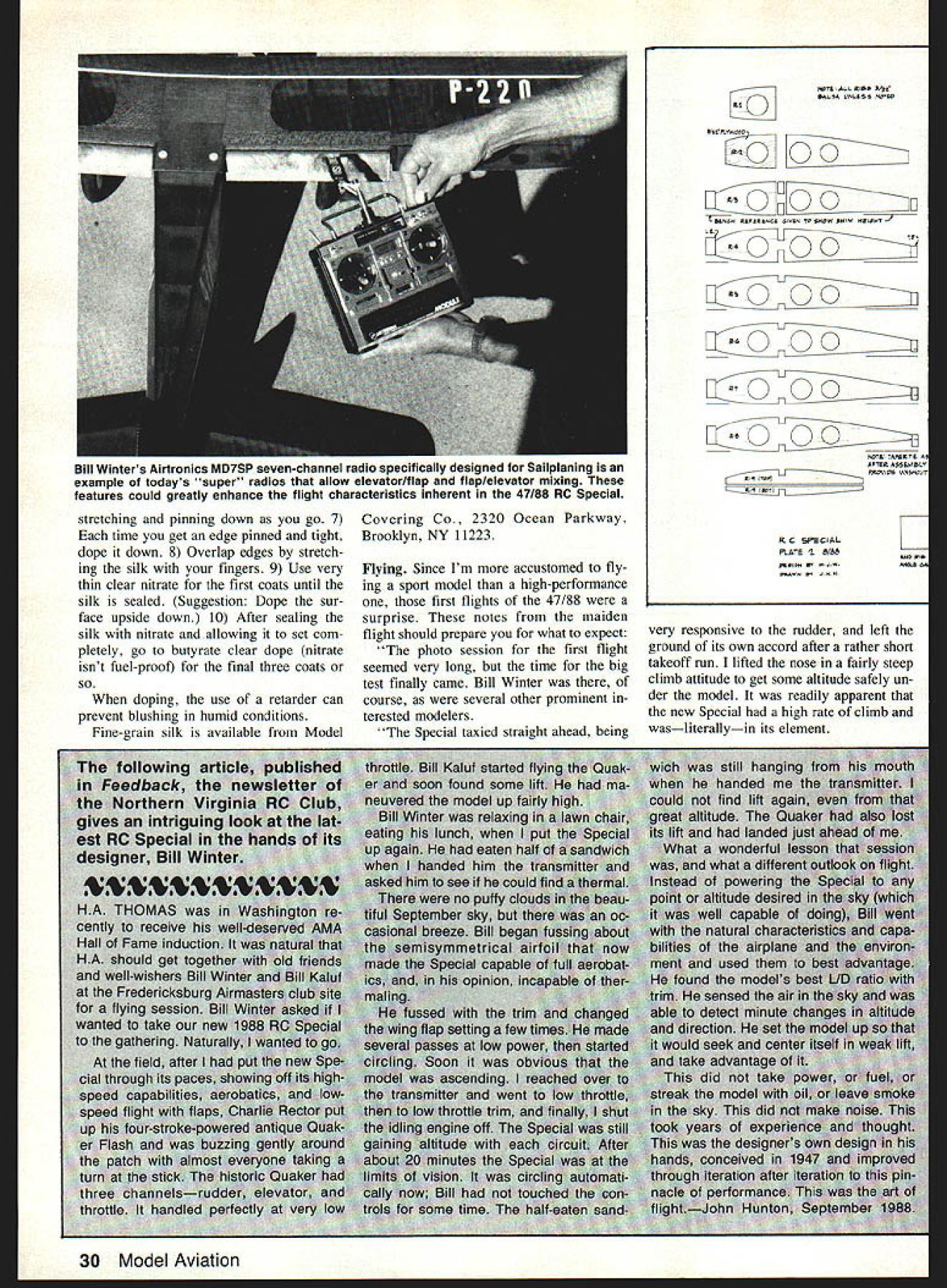
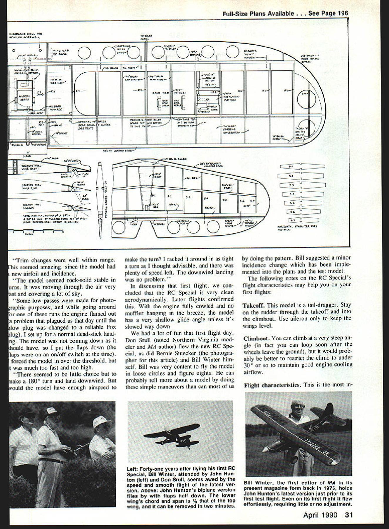

