
Balancing Pitch Concluding three-part series STABILIZER PARALLEL TO LONGITUDINAL AXIS CHORD LINE ON LONGITUDINAL AXIS THRUST LINE PARALLEL TO LONGITUDINAL AXIS IN LEVEL AND INVERTED FLIGHT FLAPS AND ELEVATORS SHOULD BE NEUTRAL THE PITCH situation far easiest three situations trim cases its simply matter add ing taking away nose tail weight However theres scientific rule says effect advantage some aspect will accompanied disadvantage another too true because pitch balance situation probably toughest design build because pitch aspect maneu verability concerns us CL flying Unlike roll yaw need moments sometimes dont want others basic object concerned us roll yaw have zero moments around respective axes timeswe never want rolling yaw ing pitch situation compounded two basic objects want pitch some times dont want other times First want balance pitch ingwhen maneuvering like roll yaw must ideal balance situa tion Second want balance pitch ing basically two aspects maneuveringinside turns outside turns stunt ship should turn both ways equally well Balance Pitching ship perfectly balanced pitch pitching such level inverted flight sum moments around lateral axis equal zero fuselage longitudi nal axis parallel ground SOME DEFLECTION FIG 2NEEDED FOR LEVEL FLIGHT TAIL HEAVY WEIGHT LIFT CGCP / *0 -I NOSE HEAVY 44 WEIGHT / SOME DEFLECTION NEEDED FOR LEVEL FLIGHT situation thrust line chord sta bilizer should parallel longitudinal axis Also elevators flaps should neutral position Fig 1 ship flies level elevators flaps neutral means either both two things thrust line and/or chord and/or stabilizer can out line causing positive nose up nega tive nose down pitching moment negative pitching moment caused ship will have fly up control stay level positive pitching moment caused ship will have fly down control stay level Dont forget in verted flight situation reversed Once ship built impossible completely correct problems butchering planethe excep tion being thrust line out line case can add wash ers between engine lugs motor mount front rear engine can also use nylon thrust wedges better can get correct angle because give lugs com plete bearing mount chord and/or stabilizer out line youll have put up problem However may critical uncorrectable yaw roll problem ship itself can still fly smooth pattern flier will have rougher time controlling because inside outside turns will same flier will have adapt difference up down control Aside lack symmetry con trol ship situation subject unnecessary drag because means flying level deflected surfaces Deflected surfaces ideally should used maneuver used trim drag will induced consequently loss lift will result other problem causes ship fly level deflected flaps elevators 38 Model Aviation Chris Lella FIG 1 $1 CL Stunt Ships Previous articles discussed balancing roll yaw nose-heavy tail-heavy problem nose-heavy ship will require some up con trol keep ship level tail-heavy ship some down control problem easy enough correct just adding weight nose tail depending situation better come off bench nose-heavy ship because less weight will needed balance ship tail-heavy because moment arm longer tail nose However majority stunt ships usually come off bench tail-heavy consequently nose weight needed common place put nose weight back engine case hollow part top block right above crankshaft best way use nose weight buy nose-weight disc attaches crankshaft between prop prop nut way youll need less weight because will further forward moment arm longer Also weight crankshaft will act flywheel minimize possibility erratic engine run observation majority stunt ships come off bench tail-heavy has fairly obvious implication Either heavy materials used tail assemblies nose-moment arms too short good stunt fliers build lightness still come out tail-heavy must lot nose-moment arms too short long should nose-moment arm cannot answered completely right now because different designs require dif ferent moment arms different ships DOWN DEFLECTION %V TENS ION IN PUSSTAB HRODNOFLEXPOSSIBLEcj\ FIG 3 STAB o =:zJ ljo COMPRESSION IN PUSHROD IF PUSHROD IS NOT RIGID ENOUGH IT WILL FLEX COLUMN BEND WHEN UP CONTROL IS APPLIED UP DEFLECTION same design can require different nose-moment arms different materials engines used However safe ratio use 1/175 nose moment arm tail moment arm ratio must figure moment arms front nose ring Center Pressure CP stabilizer trailing edge Center Pressure figure nose ring leading edge wing trailing edge stabilizer trailing edge say because may have heard 9/ 1425 standard moment arm ratio calculated way some fliers use ratio latter method youll probably come up another tail-heavy ship 9/1425 taken George FIG 4 -rBELLCRANK CONTROL ARMS I PARALLEL TO PUSHROD I r r -I PUSH ROD PARALLEL TO LONGITUDINAL AXIS 1 -1 L1 LONGITUDINAL AXIS Aldrichs Nobler ratio method applies ships wings proportional Nobler wing As wing proportions change does 9/1425 ratio because CP will change different wing proportions true mo ment arms calculated around CP have design mind known come out tail- nose-heavy want use 1/175 ratio should leave tail-moment arm way change nose-moment arm propor tionally nose-moment arm should come out shorter its nose-heavy de sign longer its tail-heavy design Dont change tail-moment arm tail-moment arm should proportional wing dimensions turn determine CP Determining CP described end article nose-heavy-tail-heavy situation will critical problem its too extreme shouldnt want add ounce nose tail weight because youll increasing wing loading Anything ounce critical brings us subjective end balancing stunt ship better off noseheavy tail-heavy neutral flier must answer question himself However situations has advantages disadvantages Before describing characteristics three situations Ill first give physi cal description what being nose-heavy tail-heavy static situation determined longitudinal position CG relation CP CG center ships total mass CP center lift wing July1976 39 Balancing Pitch FIG 5 BELLCRANK IN LINE WITH LONGITUDINAL AXIS /______ Izzzzzz r LONG ITUDINAL AXIS CONTROL HORN ARM PERPENDICULAR TO BELLCRANK AND LONGITUDINAL AXIS WHEN FLAPS AND ELEVATORS ARE LIRA FIG 6 FLAP CONTROL HORN ARM PERPENDICULAR TO LONGITUDINAL AXIS 1 ELEVATOR CONTROL HORN ARM PARALLEL TO FLAP CONTROL HORN ARM PERPENDICULAR TO LONGITUDINAL AXIS IFLAP NEUTRALLONGITUDINAL AXIS balance point stunt ships CG front CP nosedown moment nose-heaviness CG behind CP taildown moment tail-heaviness Fig 2 plans youll see CP labeled Balance Point other plans youll see marked CG necessarily CG others no label just symbol Regardless ever labeled marked youll usually see high point airfoil back edge main spar should intended mean CP balance point necessarily correct position because CP varies different wing dimensions Knowing CP critical trimming balance because trim according flying characteristics individual ship However neces sary know designing balance because will determine out balance ship may Ill now describe advantages disadvantages nose-heavy tail-heavy neutrally-balanced ships Nose-heavy Nose-heavy ships popular because nose-heavy ship stable three reason nose-heavy ship has its CG further ward means have surface area behind CG area behind CG stable ship will Therefore nose-heavy ship will groove easiest will keep straight path least amount control necessary disadvantage corners cannot turned quickly tail-heavy ship lot nose-heavy ships can turn tight corners takes control control surfaces quicker snap control handle means stress wing stabilizer flaps elevators hinges Because nose-heavy ships will fatigue readily tail-heavy ship Another disadvantage will less symmetry control ship opposed symmetry available neutrally-balanced ship During inside loops instance youll need much up control bottom loop top loops will tend sag ground Tail-heavy advantage tailheavy situation briefly mentioned Corners can turned tightly ease tail-heavy ship can almost think yourself corner chance jerking corner minimized Also wing stabilizer flaps elevators hinges much less stressed noseSUM OF THESE MOMENTS WILL DETERMINE PITCHING TENDENCY IT SHOULD BE ZERO FIG 7 FORCE OF THRUST CAUSING NEGATIVE MOMENT THRUST LINE ABOVE CG FORCE OF DRAG ON TAIL SURFACES CAUSING POSITIVE MOMENT DRAG ABOVE CG CG NOT NECESSARILY CP 4jFORCE OF DRAG ON LG CAUSING NEGATIVE MOMENT DRAG BELOW CG 40 Model Aviation -U 4 ELEVATOR NEUTRAL heavy ship youll getting less fatigue advantages tail-heavy ship stop main disadvantage relatively unstable because CG fur ther back wing Therefore ratio aft forward surface area decreases Consequently decrease stabil ity will require control flier groove particular path Also like nose-heavy ship will lack symmetry controlling During inside loops instance youll need up control top loop bottom loops will tend rise away ground Another disadvantage tailheavy ship subject clumsy take-offs landings will tend jump quickly ground take-off landing want smooth descent will fight descending attitude nose-up tendency nose-up attitude will give angle attack airfoil causing lift drag will make ship balloon its way down instead glid ing landing ship should look like wants come down being con trolled down nose-heavy ship will tail-heavy ship will look like wants stay up being forced down Naxtral main advantage ship neither nose-heavy tail-heavy symmetry control instance doing loops top bottom extremes loop should require same control As far everything else goes its mean between nose-heavy tail-heavy characteristics concluding section balance pitching must remind pitch balance wide open preference ship little nose-heavy best majority fliers comparing characteristics extremes noseheavy ship can advantageous However National Champion Doug Stout flies tail-heavy ship him fly nose-heavy ship may detrimental person like something within individuals percep tion conception control deter mines advantage helping someone find advantage pitch balance sug gest becoming well experienced extremes choose positive situation Balance Pitching ship has positive negative pitchinside outside turning respec tively ideal situation have sym metrical inside outside control turns sensitivity stability inside turns should equal outside turns up control needed inside turn down control needed outside turn equal pitching balance another added variable flier must adapt flier already has adapt vari ables weather conditions affecting enFOR SHIPS TURNING TIGHTER OUTSIDES UP FIG 8 SHORTEN DOWN ARM AS MUCH AS NECESSARY K2J FOR SHIPS TURNING TIGHTER INSIDES UP SHORTEN UP ARM AS MUCH AS NECESSARY DOWN FIG 9APPROXIMATE LOCATION OF THE CENTER OF PRESSURE -CR L 1I C-1-TIPCHORD CR ROOTCHORD TMEANCHORD TER CHORD POINT CP ER OF PRESSURE gine runs wind conditions affecting maneuvers different points flying hemisphere changes line tension different attitudes flight Lack symmetry between inside outside turns compounds matters Unlike can avoided pattern much easier fly various reasons can cause Ill start simplest work toward complex follows Thrust Line and/or chord and/or stabilizer out line men tioned section balance pitching out line ship will turn tighter direc tion moment caused mis alignment acting Flexible Pushrods Because way standard control linkage stunt flying set up have tension pushrods down control compres sion pushrods up down control applied can never flex pushrods because nature tension does allow up control applied compression causes tendency rods flex known column bend longer thinner less rigid rod less compression required bend So pushrod does have enough characteris tics withstand compression caused up control will flex Because flex ship will sensitive up control will down control consequently ship will turn outside maneuvers tighter inside Fig 3 two solutions problem use thick enough rod 35 size stunt ship will fine 3/32 pushrod other solution put bearings pushrod has go through ships bulkheads plans indicate dont recommend because can hinder smoothness controls friction bearings Some plans indicate three bearings three bulkheads between wing tail have use bearings just use bulkhead closest midway point between wing tail Different lengths arms bellcrank connected up down leadouts arms bellcrank leadouts connected different lengths inside outside turning will different Say instance arm connected down leadout shorter arm connected up leadout ship will sensitive down control up continued page 92 July1976 41 Cardinal Sinner continued moves sensitive model will become Line tension also affected increases forward shifts CG Make change time test fly Flight trim can get much involved basics will take care problems might mention other thing De troiter wings seem have characteristic rumble flight due drum effect non-sheeted wing may notice center circle may mentioned flying buddies See winners circle Museum/Mills continued page 15 lucky tinkerers often made out brothers came interested flying assembled studied scientific knowledge available experimented kites gliders found gliders did perform ex pected Wrights concluded Lilienthal calculations airfoil lift drag commonly accepted errone ous Consequently constructed Build Dynateks Solid State RC Kits Save S$S OLOWORIVER fast easy starts indicates shorts open plugs Kit $1995 $3495 assmb &h SERVO TESTER completely check servos Kits $1195 $1695 assmb &h AUTO SERVO TESTER man ualplus feature drive servos back & forth break servos analyze dead spots Kit $1695 $2195 assmb &h BankAmericardMaster Charge DYNATEK PO Box 396 Derby KS 67037 1901 wind tunnel produced winds 25 35 miles per hour 200 airfoil sections tested Wright brothers before confi dent assembled first reliable tables air pressure curved surfaces armed accu rate information Wrights came up flyable plane replica wind tunnel reconstructed Museum under supervision Orville Wright part Wright brothers exhibit aviation has romantic period has first World War years following Certainly collection planes first World War popular visitors United States declared war April 1917 Signal Corps Aviation Section 250 airplanesnot combat worthy Despite tremen dous effort American industry able produce American-designed plane time see actual combat Americans used British designed de Havilland DH4s Most built Day ton Dayton-Wright Company first aerial victory April 1918 taken get going final seven months saw 756 airplanes 76 balloons shot down America new kind hero 31 aces Captain Eddie Rickenbacker famous After war came barnstorming daredevils country fairs wing walkers mock dog fights beneath flamboyance excitement struggle going between saw significance airplane saw exotic toy Men vision notably Brig Gen Billy Mitchell attempted promote military future plane second World War ended dis pute explosively Air powerespecially American air powerwas decisive fac tor allied victory best known planes America other nations Air Force Muse um arrangement chrono logical according theater operation well visitors part Museum nostalgia tinged sadness Americas first jet XP-59A made its initial flight October 1942 con fuse possible enemy spies wooden propeller nose version plane display its propel ler Museum area devoted jet age space almost popular antique planes Air Force Museum must-see anyone going Dayton Ohio comfortable Museum visit parking 500 cars pic nic area inside core building clean well-marked restrooms elevator restrooms handi capped need baby strollers wheelchairs avail able no admission charge parking fee Visiting hours weekdays 900 am 500 pm 1000 am 600 pm Saturdays Sundays Balancing Pitch/Lella continued page 41 because will take less movement utilize necessary down Consequently equal movement control handle ship will turn tighter outside maneuvers Unequal up down movement elevators flaps elevators flaps deflect same distance up down ship will again turn unsym metrically caused cockeyed assembly control linkage Specifi cally alignment linkage should follows 1 up down arms bellcrank form straight line should parallel its connecting pushrod elevators flaps neutral turn should parallel longitudi nal axis Fig 4 2 plane bellcrank should parallel lie longitudinal axis Fig 5 3 flap control horn arm should perpendicular bellcrank longitudinal axis elevators flaps neutral Fig 5 4 elevator control horn arm should parallel flap control horn arm other words flap control horn arm perpendicular flap elevator control horn arm should per pendicular elevator Fig 6 Improper aerodynamic balance around lateral axis vertical position thrust line surfaces causing drag concern series arti cles drag has yet mentioned cause imbalance alluded causing loss lift because drag forces ship respect roll yaw part sym metrical around respective axes 92 Model Aviation Scearman C3BRALh Ar s re. ITGNWNB R WIRONPGN04G PONDER_______OW Olo POWER * GO OF RONTAL Gin FOG RADIO CONTROL UP TO THREE CHANNELSORr OF TUG GOLDEN ERAS NTEAIESI GIROGAFTAND DELIGHT TO BUILD CIRTORO MAKER OrFOGE WORLD WARt_________NG HR AMERICAN BELL NC SkTrODkeI WIRGGFAN DOG POWER FOR W P/PER CV5 RONR GD CONTROL UP TO TOREE INGRPAR 020 PDWrR FOR FREE GRELE B TRUE CLAGNIC PLeAT OR RADIO CONTROL Ti05iQ5 IE&C FROM THE GOLDEN ERA SO WINGGPANWBNT POWER OR RUBBERS NH OS AGE 00 TEGIDENOG ADD 0% TAOFLY LINE MODELS SEE YOUR LOCAL -HOBRY OEALER0643 ASHEY FL FAIRFAX VA 22030 DAlIBALL LINK TOOLAILERON HORN WIRE Serves two uses curve ____ end safely separates hal inammw~alinks other enExcellent hook up EEEUL~AaWfits 1/16assembly strip ailerons LIIIfl~SOCthreaded ha Eliminates differential throw No187link nut No189. 2 Sets $175 STRIP AILERONTHREADED BALL LINK1/16 _ __ ICTION LINKAGE HOOK-UPFR Fully adjustable 16 Pc aileron_________ hookup complete shown No play no binding superThis new4 pieceBRAKE precision EliminatesI/threaded ball link set FRICTION BRAKE differentialfits perfectly servo throwarm holes belcranksComplete 10 pc nylon horns throt-nose wheel brake Strong tie arms and linkage hook-up I1Qeasy hookup- tures NEW case Safe 190 Just bolt 85Qhardened steel brake Should beadjustableirum other used anyOIBALL LINKfine quality plane utilizingSOCKETS Extra nylon LIILparts Requires strip aileronssockets- Fits very little 0VLPi0No 186$295all styles Du-bro ball linkspressure engage No 188 $100NO157$295 Wh.notn DU-BRO PRODUCTS INCORPORATED 480 Bonner Road Wauconda Illinois 60084 USA However respect pitch drag forces around lateral axis symmetrical along thrust account pitch moments around axis external surface exposed drag look side view almost conventionally designed stunt ship youll see vertical positions surfaces have no symmetry sur faces main concern tail section landing gear Most tail sec tions located completely above CG means force drag sur face will also above CG will cause positive nose up moment around lateral axis landing gear located below CG Consequently force drag will below CG will cause negative nose down moment around lateral axis other force acting conjunction drag thrust Most stunt ships have thrust line above CG will also cause negative moment around CG Fig 7 Ideally moments should balance out zero aspect will affect inside-outside symmetry turns dont times dont ship will turn tighter direction such case usually resulting negative moment ship turns outsides better insides means force drag landing gear force thrust causing greater moment drag tail surface acts opposite latter two forces would proper right now show drag forces calcu lated unfortunately would quite lengthy perhaps unintelligible anyone engineer However Ill generalize idea Since thrust thrust line above CG drag landing gear account significant amount nega tive moment fitting tail sur face must account equally opposing positive moment longer bulky landing gear higher thrust line above CG higher tail section must As long landing radical dimension advisable stick ratio stabi lizer height thrust height above CG suggest using ratio least 21 ships conventional vertical fin verti cal stab rudder Use least 31 vertical fin other words ship conventional vertical fin has thrust line e CG stab should least 1 above CG etc ratio cannot used ships thrust line right CG stab should least e CG vertical fin least 1 above vertical fin latter dimensions 35 ships wing area 550-600 sq Other sizes should scaled proportionally summarizing section balance pitching keep mind causes imbalance can combine cause lack symmetry However total factors will yield just symp tom ship finished youll either have design turns tighter out side tighter inside well balanced ship respect pitching symmetry ship has undesired symptom ob viously ridiculous directly correct causes because requires digging ship exception mis aligned thrust line way ever correct lack symmetry regard less cause can compensate changing lengths arms control handle rule shorten arm control turns tighter ship turns tighter outsides shorten down arm control handle vice versa Doing gives opposite con trol moments compensating unsym metrical flying moments Fig 8 Finding Center Pressure CP Center Pressure defined point wing resultant lift drag forces wing act term rarely used anymore aerody namicists because cannot used ana lyticaily anything other sym metrical airfoil wont explain because lengthy does directly concern us Technically would better July1976 93 HEY-THERE! Have paying $600 1/2 oz fast glue gotten zipped 50il will get twice much GLU-IT! Have paying $575 1/2 oz fast glue gotten burned 75i1 will get twice much GLU-IT! Have paying $895 1 oz fast glue gotten stuck $245 less will get same amount GLU-IT! GLU4T! BEST new ultra-fast glues Balsaand almost thing Its light fast colorless strong comes 1 oz un breakable bottle dis penser tip Price $650 postpaid Calif residents add 6% tax Tyro Model & Supply PO Box 11511 Palo Alto Calif 94306 94 Model Aviation Pitch continued use term Aerodynamic Center However equations finding much complex symmetri cal airfoil what use stunt would come out approximately same Center Pressure So since term Center Pressure bit self-explanatory since can used analytically symmetrical airfoils also since its calculation simpler will use Center Pressure can found following steps 1 Figure Mean Chord fig ured averaging Root Chord Tip Chord Say instance Root Chord 13 Tip Chord 9 Mean Chord would 11 Flaps included values 2 Layout planform wing on- paper try accurate dimensions 3 Draw Mean Chord 11 11 both wing panels 4 Figure Quarter Chord Points Mean Chords would 11 x Quarter Chord Points 275 leading edge Mean Chords Mark points 5 Connect Quarter Chord points straight line Center Pres sure line crosses center wing Fig 9 pitch situation has now has ex plained balancing concerned However should acquaint yourself particular dimensions ship determine certain characteristics pitchmainly characteristics turning capability particular ship will turn tighter tail-heavy noseheavy things affect ships turning radius Longi tudinal moment arms wing aspect ratio stab-devator aspect ratio area wing taper prop gyration other factors involved did describe because affect pitch balance concerned except mention moment arms did concern balance situa tion may have noticed throughout series term trim used spar ingly dispel ideas balance synonymous trim Trim what ship make balanced However complete balance situation comprised trimming Good balance better manifested good de sign construction because trimming compensation mistakes design construction end well trimmed ship makes some what happens end what counts others its end reached therefore good end will have certain lack satisfaction com pensating mistakes spoke good balance rather good trim anything understood reread think over address 2850 E 196 St Bronx NY 10461if have questions prod uctrviewprod uctre iwprod uctre vie wprod uctre view m LEPER br CLAUOE McCULLWflM SUPER SPORT Oipfld VV MIKE GRETZ Dynamic Duo Klipper Super S. Claude Mccullough designs Sig combine ready-touse flat-bottom foam wing balsa fuselage tail Klipper $1895 features handy printed fuselage sides permitting building internal structure directly wood Trike gear cabin config uration kit includes such niceties coil spring nose gear one-piece ABS molded cowling alumi num main gear aluminum motor mounts Both models take 09 15 engines room standard size radios intended 2 3 channels span 45 Super Sport top-of-fuselage wing stallation two-wheel gear Excepting gear differences has same kit features Klipper Price $1795 Sig Manufacturing Co. Monte zuma Iowa 50171 FF Duration/Meuser continued page 35 siderably inertiaflywheel effect FAI winch think simply natural consequence faster gearing Bob also does custom short-run machine shop work reasonable prices Check Bob Wilders Model Machine Works 2010 Boston Irving TX 75061 Boonis Such NFFS Supplies now carries three different sizes tapered fiberglass-phenolic tubes used tailbooms 42-in long small est tapering 53 29 diam eter weighing 33 grams popular with

Edition: Model Aviation - 1976/07
Page Numbers: 38, 39, 40, 41, 92, 93, 94

Edition: Model Aviation - 1976/07
Page Numbers: 38, 39, 40, 41, 92, 93, 94
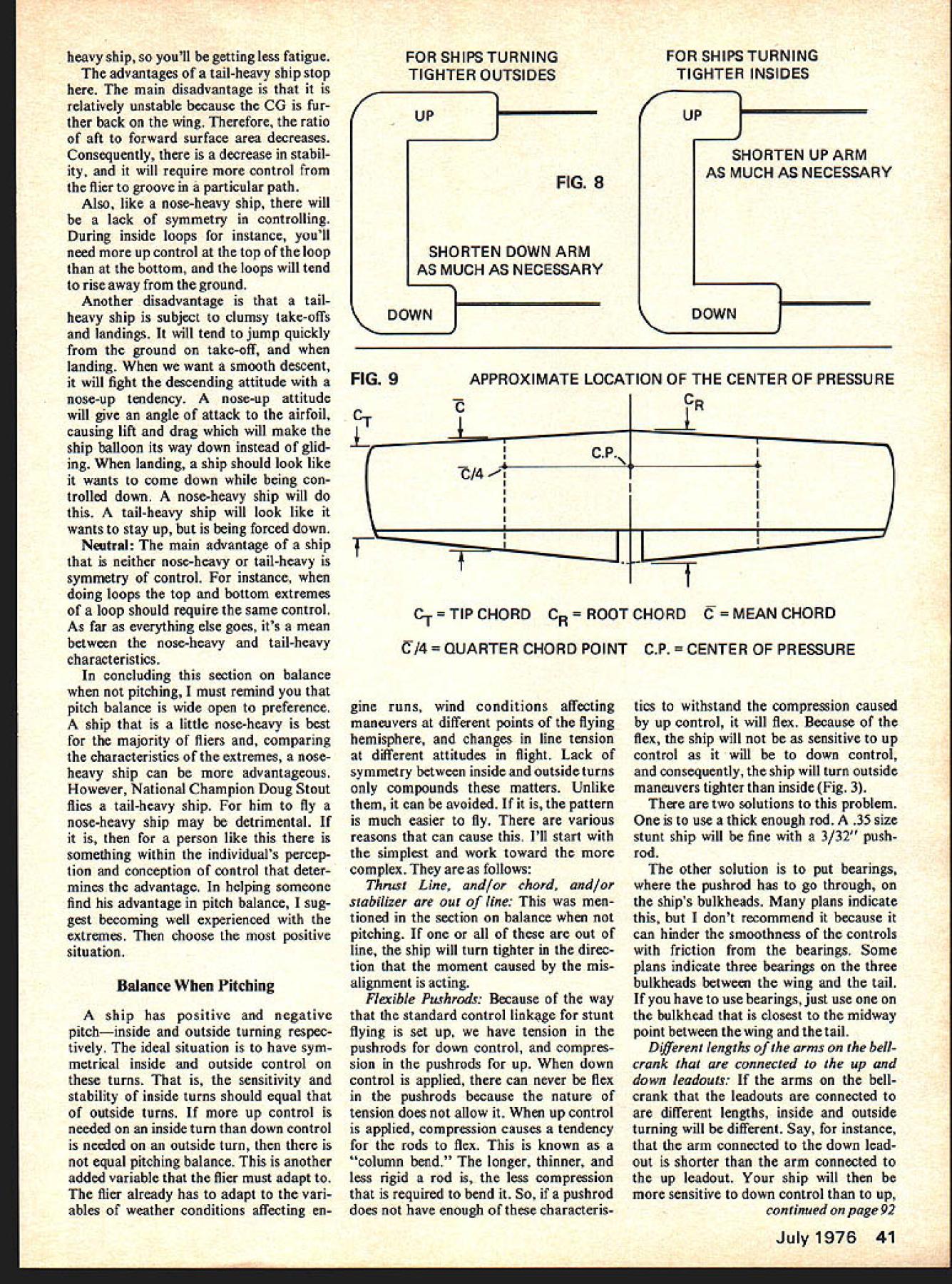
Balancing Pitch Concluding three-part series STABILIZER PARALLEL TO LONGITUDINAL AXIS CHORD LINE ON LONGITUDINAL AXIS THRUST LINE PARALLEL TO LONGITUDINAL AXIS IN LEVEL AND INVERTED FLIGHT FLAPS AND ELEVATORS SHOULD BE NEUTRAL THE PITCH situation far easiest three situations trim cases its simply matter add ing taking away nose tail weight However theres scientific rule says effect advantage some aspect will accompanied disadvantage another too true because pitch balance situation probably toughest design build because pitch aspect maneu verability concerns us CL flying Unlike roll yaw need moments sometimes dont want others basic object concerned us roll yaw have zero moments around respective axes timeswe never want rolling yaw ing pitch situation compounded two basic objects want pitch some times dont want other times First want balance pitch ingwhen maneuvering like roll yaw must ideal balance situa tion Second want balance pitch ing basically two aspects maneuveringinside turns outside turns stunt ship should turn both ways equally well Balance Pitching ship perfectly balanced pitch pitching such level inverted flight sum moments around lateral axis equal zero fuselage longitudi nal axis parallel ground SOME DEFLECTION FIG 2NEEDED FOR LEVEL FLIGHT TAIL HEAVY WEIGHT LIFT CGCP / *0 -I NOSE HEAVY 44 WEIGHT / SOME DEFLECTION NEEDED FOR LEVEL FLIGHT situation thrust line chord sta bilizer should parallel longitudinal axis Also elevators flaps should neutral position Fig 1 ship flies level elevators flaps neutral means either both two things thrust line and/or chord and/or stabilizer can out line causing positive nose up nega tive nose down pitching moment negative pitching moment caused ship will have fly up control stay level positive pitching moment caused ship will have fly down control stay level Dont forget in verted flight situation reversed Once ship built impossible completely correct problems butchering planethe excep tion being thrust line out line case can add wash ers between engine lugs motor mount front rear engine can also use nylon thrust wedges better can get correct angle because give lugs com plete bearing mount chord and/or stabilizer out line youll have put up problem However may critical uncorrectable yaw roll problem ship itself can still fly smooth pattern flier will have rougher time controlling because inside outside turns will same flier will have adapt difference up down control Aside lack symmetry con trol ship situation subject unnecessary drag because means flying level deflected surfaces Deflected surfaces ideally should used maneuver used trim drag will induced consequently loss lift will result other problem causes ship fly level deflected flaps elevators 38 Model Aviation Chris Lella FIG 1 $1 CL Stunt Ships Previous articles discussed balancing roll yaw nose-heavy tail-heavy problem nose-heavy ship will require some up con trol keep ship level tail-heavy ship some down control problem easy enough correct just adding weight nose tail depending situation better come off bench nose-heavy ship because less weight will needed balance ship tail-heavy because moment arm longer tail nose However majority stunt ships usually come off bench tail-heavy consequently nose weight needed common place put nose weight back engine case hollow part top block right above crankshaft best way use nose weight buy nose-weight disc attaches crankshaft between prop prop nut way youll need less weight because will further forward moment arm longer Also weight crankshaft will act flywheel minimize possibility erratic engine run observation majority stunt ships come off bench tail-heavy has fairly obvious implication Either heavy materials used tail assemblies nose-moment arms too short good stunt fliers build lightness still come out tail-heavy must lot nose-moment arms too short long should nose-moment arm cannot answered completely right now because different designs require dif ferent moment arms different ships DOWN DEFLECTION %V TENS ION IN PUSSTAB HRODNOFLEXPOSSIBLEcj\ FIG 3 STAB o =:zJ ljo COMPRESSION IN PUSHROD IF PUSHROD IS NOT RIGID ENOUGH IT WILL FLEX COLUMN BEND WHEN UP CONTROL IS APPLIED UP DEFLECTION same design can require different nose-moment arms different materials engines used However safe ratio use 1/175 nose moment arm tail moment arm ratio must figure moment arms front nose ring Center Pressure CP stabilizer trailing edge Center Pressure figure nose ring leading edge wing trailing edge stabilizer trailing edge say because may have heard 9/ 1425 standard moment arm ratio calculated way some fliers use ratio latter method youll probably come up another tail-heavy ship 9/1425 taken George FIG 4 -rBELLCRANK CONTROL ARMS I PARALLEL TO PUSHROD I r r -I PUSH ROD PARALLEL TO LONGITUDINAL AXIS 1 -1 L1 LONGITUDINAL AXIS Aldrichs Nobler ratio method applies ships wings proportional Nobler wing As wing proportions change does 9/1425 ratio because CP will change different wing proportions true mo ment arms calculated around CP have design mind known come out tail- nose-heavy want use 1/175 ratio should leave tail-moment arm way change nose-moment arm propor tionally nose-moment arm should come out shorter its nose-heavy de sign longer its tail-heavy design Dont change tail-moment arm tail-moment arm should proportional wing dimensions turn determine CP Determining CP described end article nose-heavy-tail-heavy situation will critical problem its too extreme shouldnt want add ounce nose tail weight because youll increasing wing loading Anything ounce critical brings us subjective end balancing stunt ship better off noseheavy tail-heavy neutral flier must answer question himself However situations has advantages disadvantages Before describing characteristics three situations Ill first give physi cal description what being nose-heavy tail-heavy static situation determined longitudinal position CG relation CP CG center ships total mass CP center lift wing July1976 39 Balancing Pitch FIG 5 BELLCRANK IN LINE WITH LONGITUDINAL AXIS /______ Izzzzzz r LONG ITUDINAL AXIS CONTROL HORN ARM PERPENDICULAR TO BELLCRANK AND LONGITUDINAL AXIS WHEN FLAPS AND ELEVATORS ARE LIRA FIG 6 FLAP CONTROL HORN ARM PERPENDICULAR TO LONGITUDINAL AXIS 1 ELEVATOR CONTROL HORN ARM PARALLEL TO FLAP CONTROL HORN ARM PERPENDICULAR TO LONGITUDINAL AXIS IFLAP NEUTRALLONGITUDINAL AXIS balance point stunt ships CG front CP nosedown moment nose-heaviness CG behind CP taildown moment tail-heaviness Fig 2 plans youll see CP labeled Balance Point other plans youll see marked CG necessarily CG others no label just symbol Regardless ever labeled marked youll usually see high point airfoil back edge main spar should intended mean CP balance point necessarily correct position because CP varies different wing dimensions Knowing CP critical trimming balance because trim according flying characteristics individual ship However neces sary know designing balance because will determine out balance ship may Ill now describe advantages disadvantages nose-heavy tail-heavy neutrally-balanced ships Nose-heavy Nose-heavy ships popular because nose-heavy ship stable three reason nose-heavy ship has its CG further ward means have surface area behind CG area behind CG stable ship will Therefore nose-heavy ship will groove easiest will keep straight path least amount control necessary disadvantage corners cannot turned quickly tail-heavy ship lot nose-heavy ships can turn tight corners takes control control surfaces quicker snap control handle means stress wing stabilizer flaps elevators hinges Because nose-heavy ships will fatigue readily tail-heavy ship Another disadvantage will less symmetry control ship opposed symmetry available neutrally-balanced ship During inside loops instance youll need much up control bottom loop top loops will tend sag ground Tail-heavy advantage tailheavy situation briefly mentioned Corners can turned tightly ease tail-heavy ship can almost think yourself corner chance jerking corner minimized Also wing stabilizer flaps elevators hinges much less stressed noseSUM OF THESE MOMENTS WILL DETERMINE PITCHING TENDENCY IT SHOULD BE ZERO FIG 7 FORCE OF THRUST CAUSING NEGATIVE MOMENT THRUST LINE ABOVE CG FORCE OF DRAG ON TAIL SURFACES CAUSING POSITIVE MOMENT DRAG ABOVE CG CG NOT NECESSARILY CP 4jFORCE OF DRAG ON LG CAUSING NEGATIVE MOMENT DRAG BELOW CG 40 Model Aviation -U 4 ELEVATOR NEUTRAL heavy ship youll getting less fatigue advantages tail-heavy ship stop main disadvantage relatively unstable because CG fur ther back wing Therefore ratio aft forward surface area decreases Consequently decrease stabil ity will require control flier groove particular path Also like nose-heavy ship will lack symmetry controlling During inside loops instance youll need up control top loop bottom loops will tend rise away ground Another disadvantage tailheavy ship subject clumsy take-offs landings will tend jump quickly ground take-off landing want smooth descent will fight descending attitude nose-up tendency nose-up attitude will give angle attack airfoil causing lift drag will make ship balloon its way down instead glid ing landing ship should look like wants come down being con trolled down nose-heavy ship will tail-heavy ship will look like wants stay up being forced down Naxtral main advantage ship neither nose-heavy tail-heavy symmetry control instance doing loops top bottom extremes loop should require same control As far everything else goes its mean between nose-heavy tail-heavy characteristics concluding section balance pitching must remind pitch balance wide open preference ship little nose-heavy best majority fliers comparing characteristics extremes noseheavy ship can advantageous However National Champion Doug Stout flies tail-heavy ship him fly nose-heavy ship may detrimental person like something within individuals percep tion conception control deter mines advantage helping someone find advantage pitch balance sug gest becoming well experienced extremes choose positive situation Balance Pitching ship has positive negative pitchinside outside turning respec tively ideal situation have sym metrical inside outside control turns sensitivity stability inside turns should equal outside turns up control needed inside turn down control needed outside turn equal pitching balance another added variable flier must adapt flier already has adapt vari ables weather conditions affecting enFOR SHIPS TURNING TIGHTER OUTSIDES UP FIG 8 SHORTEN DOWN ARM AS MUCH AS NECESSARY K2J FOR SHIPS TURNING TIGHTER INSIDES UP SHORTEN UP ARM AS MUCH AS NECESSARY DOWN FIG 9APPROXIMATE LOCATION OF THE CENTER OF PRESSURE -CR L 1I C-1-TIPCHORD CR ROOTCHORD TMEANCHORD TER CHORD POINT CP ER OF PRESSURE gine runs wind conditions affecting maneuvers different points flying hemisphere changes line tension different attitudes flight Lack symmetry between inside outside turns compounds matters Unlike can avoided pattern much easier fly various reasons can cause Ill start simplest work toward complex follows Thrust Line and/or chord and/or stabilizer out line men tioned section balance pitching out line ship will turn tighter direc tion moment caused mis alignment acting Flexible Pushrods Because way standard control linkage stunt flying set up have tension pushrods down control compres sion pushrods up down control applied can never flex pushrods because nature tension does allow up control applied compression causes tendency rods flex known column bend longer thinner less rigid rod less compression required bend So pushrod does have enough characteris tics withstand compression caused up control will flex Because flex ship will sensitive up control will down control consequently ship will turn outside maneuvers tighter inside Fig 3 two solutions problem use thick enough rod 35 size stunt ship will fine 3/32 pushrod other solution put bearings pushrod has go through ships bulkheads plans indicate dont recommend because can hinder smoothness controls friction bearings Some plans indicate three bearings three bulkheads between wing tail have use bearings just use bulkhead closest midway point between wing tail Different lengths arms bellcrank connected up down leadouts arms bellcrank leadouts connected different lengths inside outside turning will different Say instance arm connected down leadout shorter arm connected up leadout ship will sensitive down control up continued page 92 July1976 41 Cardinal Sinner continued moves sensitive model will become Line tension also affected increases forward shifts CG Make change time test fly Flight trim can get much involved basics will take care problems might mention other thing De troiter wings seem have characteristic rumble flight due drum effect non-sheeted wing may notice center circle may mentioned flying buddies See winners circle Museum/Mills continued page 15 lucky tinkerers often made out brothers came interested flying assembled studied scientific knowledge available experimented kites gliders found gliders did perform ex pected Wrights concluded Lilienthal calculations airfoil lift drag commonly accepted errone ous Consequently constructed Build Dynateks Solid State RC Kits Save S$S OLOWORIVER fast easy starts indicates shorts open plugs Kit $1995 $3495 assmb &h SERVO TESTER completely check servos Kits $1195 $1695 assmb &h AUTO SERVO TESTER man ualplus feature drive servos back & forth break servos analyze dead spots Kit $1695 $2195 assmb &h BankAmericardMaster Charge DYNATEK PO Box 396 Derby KS 67037 1901 wind tunnel produced winds 25 35 miles per hour 200 airfoil sections tested Wright brothers before confi dent assembled first reliable tables air pressure curved surfaces armed accu rate information Wrights came up flyable plane replica wind tunnel reconstructed Museum under supervision Orville Wright part Wright brothers exhibit aviation has romantic period has first World War years following Certainly collection planes first World War popular visitors United States declared war April 1917 Signal Corps Aviation Section 250 airplanesnot combat worthy Despite tremen dous effort American industry able produce American-designed plane time see actual combat Americans used British designed de Havilland DH4s Most built Day ton Dayton-Wright Company first aerial victory April 1918 taken get going final seven months saw 756 airplanes 76 balloons shot down America new kind hero 31 aces Captain Eddie Rickenbacker famous After war came barnstorming daredevils country fairs wing walkers mock dog fights beneath flamboyance excitement struggle going between saw significance airplane saw exotic toy Men vision notably Brig Gen Billy Mitchell attempted promote military future plane second World War ended dis pute explosively Air powerespecially American air powerwas decisive fac tor allied victory best known planes America other nations Air Force Muse um arrangement chrono logical according theater operation well visitors part Museum nostalgia tinged sadness Americas first jet XP-59A made its initial flight October 1942 con fuse possible enemy spies wooden propeller nose version plane display its propel ler Museum area devoted jet age space almost popular antique planes Air Force Museum must-see anyone going Dayton Ohio comfortable Museum visit parking 500 cars pic nic area inside core building clean well-marked restrooms elevator restrooms handi capped need baby strollers wheelchairs avail able no admission charge parking fee Visiting hours weekdays 900 am 500 pm 1000 am 600 pm Saturdays Sundays Balancing Pitch/Lella continued page 41 because will take less movement utilize necessary down Consequently equal movement control handle ship will turn tighter outside maneuvers Unequal up down movement elevators flaps elevators flaps deflect same distance up down ship will again turn unsym metrically caused cockeyed assembly control linkage Specifi cally alignment linkage should follows 1 up down arms bellcrank form straight line should parallel its connecting pushrod elevators flaps neutral turn should parallel longitudi nal axis Fig 4 2 plane bellcrank should parallel lie longitudinal axis Fig 5 3 flap control horn arm should perpendicular bellcrank longitudinal axis elevators flaps neutral Fig 5 4 elevator control horn arm should parallel flap control horn arm other words flap control horn arm perpendicular flap elevator control horn arm should per pendicular elevator Fig 6 Improper aerodynamic balance around lateral axis vertical position thrust line surfaces causing drag concern series arti cles drag has yet mentioned cause imbalance alluded causing loss lift because drag forces ship respect roll yaw part sym metrical around respective axes 92 Model Aviation Scearman C3BRALh Ar s re. ITGNWNB R WIRONPGN04G PONDER_______OW Olo POWER * GO OF RONTAL Gin FOG RADIO CONTROL UP TO THREE CHANNELSORr OF TUG GOLDEN ERAS NTEAIESI GIROGAFTAND DELIGHT TO BUILD CIRTORO MAKER OrFOGE WORLD WARt_________NG HR AMERICAN BELL NC SkTrODkeI WIRGGFAN DOG POWER FOR W P/PER CV5 RONR GD CONTROL UP TO TOREE INGRPAR 020 PDWrR FOR FREE GRELE B TRUE CLAGNIC PLeAT OR RADIO CONTROL Ti05iQ5 IE&C FROM THE GOLDEN ERA SO WINGGPANWBNT POWER OR RUBBERS NH OS AGE 00 TEGIDENOG ADD 0% TAOFLY LINE MODELS SEE YOUR LOCAL -HOBRY OEALER0643 ASHEY FL FAIRFAX VA 22030 DAlIBALL LINK TOOLAILERON HORN WIRE Serves two uses curve ____ end safely separates hal inammw~alinks other enExcellent hook up EEEUL~AaWfits 1/16assembly strip ailerons LIIIfl~SOCthreaded ha Eliminates differential throw No187link nut No189. 2 Sets $175 STRIP AILERONTHREADED BALL LINK1/16 _ __ ICTION LINKAGE HOOK-UPFR Fully adjustable 16 Pc aileron_________ hookup complete shown No play no binding superThis new4 pieceBRAKE precision EliminatesI/threaded ball link set FRICTION BRAKE differentialfits perfectly servo throwarm holes belcranksComplete 10 pc nylon horns throt-nose wheel brake Strong tie arms and linkage hook-up I1Qeasy hookup- tures NEW case Safe 190 Just bolt 85Qhardened steel brake Should beadjustableirum other used anyOIBALL LINKfine quality plane utilizingSOCKETS Extra nylon LIILparts Requires strip aileronssockets- Fits very little 0VLPi0No 186$295all styles Du-bro ball linkspressure engage No 188 $100NO157$295 Wh.notn DU-BRO PRODUCTS INCORPORATED 480 Bonner Road Wauconda Illinois 60084 USA However respect pitch drag forces around lateral axis symmetrical along thrust account pitch moments around axis external surface exposed drag look side view almost conventionally designed stunt ship youll see vertical positions surfaces have no symmetry sur faces main concern tail section landing gear Most tail sec tions located completely above CG means force drag sur face will also above CG will cause positive nose up moment around lateral axis landing gear located below CG Consequently force drag will below CG will cause negative nose down moment around lateral axis other force acting conjunction drag thrust Most stunt ships have thrust line above CG will also cause negative moment around CG Fig 7 Ideally moments should balance out zero aspect will affect inside-outside symmetry turns dont times dont ship will turn tighter direction such case usually resulting negative moment ship turns outsides better insides means force drag landing gear force thrust causing greater moment drag tail surface acts opposite latter two forces would proper right now show drag forces calcu lated unfortunately would quite lengthy perhaps unintelligible anyone engineer However Ill generalize idea Since thrust thrust line above CG drag landing gear account significant amount nega tive moment fitting tail sur face must account equally opposing positive moment longer bulky landing gear higher thrust line above CG higher tail section must As long landing radical dimension advisable stick ratio stabi lizer height thrust height above CG suggest using ratio least 21 ships conventional vertical fin verti cal stab rudder Use least 31 vertical fin other words ship conventional vertical fin has thrust line e CG stab should least 1 above CG etc ratio cannot used ships thrust line right CG stab should least e CG vertical fin least 1 above vertical fin latter dimensions 35 ships wing area 550-600 sq Other sizes should scaled proportionally summarizing section balance pitching keep mind causes imbalance can combine cause lack symmetry However total factors will yield just symp tom ship finished youll either have design turns tighter out side tighter inside well balanced ship respect pitching symmetry ship has undesired symptom ob viously ridiculous directly correct causes because requires digging ship exception mis aligned thrust line way ever correct lack symmetry regard less cause can compensate changing lengths arms control handle rule shorten arm control turns tighter ship turns tighter outsides shorten down arm control handle vice versa Doing gives opposite con trol moments compensating unsym metrical flying moments Fig 8 Finding Center Pressure CP Center Pressure defined point wing resultant lift drag forces wing act term rarely used anymore aerody namicists because cannot used ana lyticaily anything other sym metrical airfoil wont explain because lengthy does directly concern us Technically would better July1976 93 HEY-THERE! Have paying $600 1/2 oz fast glue gotten zipped 50il will get twice much GLU-IT! Have paying $575 1/2 oz fast glue gotten burned 75i1 will get twice much GLU-IT! Have paying $895 1 oz fast glue gotten stuck $245 less will get same amount GLU-IT! GLU4T! BEST new ultra-fast glues Balsaand almost thing Its light fast colorless strong comes 1 oz un breakable bottle dis penser tip Price $650 postpaid Calif residents add 6% tax Tyro Model & Supply PO Box 11511 Palo Alto Calif 94306 94 Model Aviation Pitch continued use term Aerodynamic Center However equations finding much complex symmetri cal airfoil what use stunt would come out approximately same Center Pressure So since term Center Pressure bit self-explanatory since can used analytically symmetrical airfoils also since its calculation simpler will use Center Pressure can found following steps 1 Figure Mean Chord fig ured averaging Root Chord Tip Chord Say instance Root Chord 13 Tip Chord 9 Mean Chord would 11 Flaps included values 2 Layout planform wing on- paper try accurate dimensions 3 Draw Mean Chord 11 11 both wing panels 4 Figure Quarter Chord Points Mean Chords would 11 x Quarter Chord Points 275 leading edge Mean Chords Mark points 5 Connect Quarter Chord points straight line Center Pres sure line crosses center wing Fig 9 pitch situation has now has ex plained balancing concerned However should acquaint yourself particular dimensions ship determine certain characteristics pitchmainly characteristics turning capability particular ship will turn tighter tail-heavy noseheavy things affect ships turning radius Longi tudinal moment arms wing aspect ratio stab-devator aspect ratio area wing taper prop gyration other factors involved did describe because affect pitch balance concerned except mention moment arms did concern balance situa tion may have noticed throughout series term trim used spar ingly dispel ideas balance synonymous trim Trim what ship make balanced However complete balance situation comprised trimming Good balance better manifested good de sign construction because trimming compensation mistakes design construction end well trimmed ship makes some what happens end what counts others its end reached therefore good end will have certain lack satisfaction com pensating mistakes spoke good balance rather good trim anything understood reread think over address 2850 E 196 St Bronx NY 10461if have questions prod uctrviewprod uctre iwprod uctre vie wprod uctre view m LEPER br CLAUOE McCULLWflM SUPER SPORT Oipfld VV MIKE GRETZ Dynamic Duo Klipper Super S. Claude Mccullough designs Sig combine ready-touse flat-bottom foam wing balsa fuselage tail Klipper $1895 features handy printed fuselage sides permitting building internal structure directly wood Trike gear cabin config uration kit includes such niceties coil spring nose gear one-piece ABS molded cowling alumi num main gear aluminum motor mounts Both models take 09 15 engines room standard size radios intended 2 3 channels span 45 Super Sport top-of-fuselage wing stallation two-wheel gear Excepting gear differences has same kit features Klipper Price $1795 Sig Manufacturing Co. Monte zuma Iowa 50171 FF Duration/Meuser continued page 35 siderably inertiaflywheel effect FAI winch think simply natural consequence faster gearing Bob also does custom short-run machine shop work reasonable prices Check Bob Wilders Model Machine Works 2010 Boston Irving TX 75061 Boonis Such NFFS Supplies now carries three different sizes tapered fiberglass-phenolic tubes used tailbooms 42-in long small est tapering 53 29 diam eter weighing 33 grams popular with

Edition: Model Aviation - 1976/07
Page Numbers: 38, 39, 40, 41, 92, 93, 94
Balancing Pitch Concluding three-part series STABILIZER PARALLEL TO LONGITUDINAL AXIS CHORD LINE ON LONGITUDINAL AXIS THRUST LINE PARALLEL TO LONGITUDINAL AXIS IN LEVEL AND INVERTED FLIGHT FLAPS AND ELEVATORS SHOULD BE NEUTRAL THE PITCH situation far easiest three situations trim cases its simply matter add ing taking away nose tail weight However theres scientific rule says effect advantage some aspect will accompanied disadvantage another too true because pitch balance situation probably toughest design build because pitch aspect maneu verability concerns us CL flying Unlike roll yaw need moments sometimes dont want others basic object concerned us roll yaw have zero moments around respective axes timeswe never want rolling yaw ing pitch situation compounded two basic objects want pitch some times dont want other times First want balance pitch ingwhen maneuvering like roll yaw must ideal balance situa tion Second want balance pitch ing basically two aspects maneuveringinside turns outside turns stunt ship should turn both ways equally well Balance Pitching ship perfectly balanced pitch pitching such level inverted flight sum moments around lateral axis equal zero fuselage longitudi nal axis parallel ground SOME DEFLECTION FIG 2NEEDED FOR LEVEL FLIGHT TAIL HEAVY WEIGHT LIFT CGCP / *0 -I NOSE HEAVY 44 WEIGHT / SOME DEFLECTION NEEDED FOR LEVEL FLIGHT situation thrust line chord sta bilizer should parallel longitudinal axis Also elevators flaps should neutral position Fig 1 ship flies level elevators flaps neutral means either both two things thrust line and/or chord and/or stabilizer can out line causing positive nose up nega tive nose down pitching moment negative pitching moment caused ship will have fly up control stay level positive pitching moment caused ship will have fly down control stay level Dont forget in verted flight situation reversed Once ship built impossible completely correct problems butchering planethe excep tion being thrust line out line case can add wash ers between engine lugs motor mount front rear engine can also use nylon thrust wedges better can get correct angle because give lugs com plete bearing mount chord and/or stabilizer out line youll have put up problem However may critical uncorrectable yaw roll problem ship itself can still fly smooth pattern flier will have rougher time controlling because inside outside turns will same flier will have adapt difference up down control Aside lack symmetry con trol ship situation subject unnecessary drag because means flying level deflected surfaces Deflected surfaces ideally should used maneuver used trim drag will induced consequently loss lift will result other problem causes ship fly level deflected flaps elevators 38 Model Aviation Chris Lella FIG 1 $1 CL Stunt Ships Previous articles discussed balancing roll yaw nose-heavy tail-heavy problem nose-heavy ship will require some up con trol keep ship level tail-heavy ship some down control problem easy enough correct just adding weight nose tail depending situation better come off bench nose-heavy ship because less weight will needed balance ship tail-heavy because moment arm longer tail nose However majority stunt ships usually come off bench tail-heavy consequently nose weight needed common place put nose weight back engine case hollow part top block right above crankshaft best way use nose weight buy nose-weight disc attaches crankshaft between prop prop nut way youll need less weight because will further forward moment arm longer Also weight crankshaft will act flywheel minimize possibility erratic engine run observation majority stunt ships come off bench tail-heavy has fairly obvious implication Either heavy materials used tail assemblies nose-moment arms too short good stunt fliers build lightness still come out tail-heavy must lot nose-moment arms too short long should nose-moment arm cannot answered completely right now because different designs require dif ferent moment arms different ships DOWN DEFLECTION %V TENS ION IN PUSSTAB HRODNOFLEXPOSSIBLEcj\ FIG 3 STAB o =:zJ ljo COMPRESSION IN PUSHROD IF PUSHROD IS NOT RIGID ENOUGH IT WILL FLEX COLUMN BEND WHEN UP CONTROL IS APPLIED UP DEFLECTION same design can require different nose-moment arms different materials engines used However safe ratio use 1/175 nose moment arm tail moment arm ratio must figure moment arms front nose ring Center Pressure CP stabilizer trailing edge Center Pressure figure nose ring leading edge wing trailing edge stabilizer trailing edge say because may have heard 9/ 1425 standard moment arm ratio calculated way some fliers use ratio latter method youll probably come up another tail-heavy ship 9/1425 taken George FIG 4 -rBELLCRANK CONTROL ARMS I PARALLEL TO PUSHROD I r r -I PUSH ROD PARALLEL TO LONGITUDINAL AXIS 1 -1 L1 LONGITUDINAL AXIS Aldrichs Nobler ratio method applies ships wings proportional Nobler wing As wing proportions change does 9/1425 ratio because CP will change different wing proportions true mo ment arms calculated around CP have design mind known come out tail- nose-heavy want use 1/175 ratio should leave tail-moment arm way change nose-moment arm propor tionally nose-moment arm should come out shorter its nose-heavy de sign longer its tail-heavy design Dont change tail-moment arm tail-moment arm should proportional wing dimensions turn determine CP Determining CP described end article nose-heavy-tail-heavy situation will critical problem its too extreme shouldnt want add ounce nose tail weight because youll increasing wing loading Anything ounce critical brings us subjective end balancing stunt ship better off noseheavy tail-heavy neutral flier must answer question himself However situations has advantages disadvantages Before describing characteristics three situations Ill first give physi cal description what being nose-heavy tail-heavy static situation determined longitudinal position CG relation CP CG center ships total mass CP center lift wing July1976 39 Balancing Pitch FIG 5 BELLCRANK IN LINE WITH LONGITUDINAL AXIS /______ Izzzzzz r LONG ITUDINAL AXIS CONTROL HORN ARM PERPENDICULAR TO BELLCRANK AND LONGITUDINAL AXIS WHEN FLAPS AND ELEVATORS ARE LIRA FIG 6 FLAP CONTROL HORN ARM PERPENDICULAR TO LONGITUDINAL AXIS 1 ELEVATOR CONTROL HORN ARM PARALLEL TO FLAP CONTROL HORN ARM PERPENDICULAR TO LONGITUDINAL AXIS IFLAP NEUTRALLONGITUDINAL AXIS balance point stunt ships CG front CP nosedown moment nose-heaviness CG behind CP taildown moment tail-heaviness Fig 2 plans youll see CP labeled Balance Point other plans youll see marked CG necessarily CG others no label just symbol Regardless ever labeled marked youll usually see high point airfoil back edge main spar should intended mean CP balance point necessarily correct position because CP varies different wing dimensions Knowing CP critical trimming balance because trim according flying characteristics individual ship However neces sary know designing balance because will determine out balance ship may Ill now describe advantages disadvantages nose-heavy tail-heavy neutrally-balanced ships Nose-heavy Nose-heavy ships popular because nose-heavy ship stable three reason nose-heavy ship has its CG further ward means have surface area behind CG area behind CG stable ship will Therefore nose-heavy ship will groove easiest will keep straight path least amount control necessary disadvantage corners cannot turned quickly tail-heavy ship lot nose-heavy ships can turn tight corners takes control control surfaces quicker snap control handle means stress wing stabilizer flaps elevators hinges Because nose-heavy ships will fatigue readily tail-heavy ship Another disadvantage will less symmetry control ship opposed symmetry available neutrally-balanced ship During inside loops instance youll need much up control bottom loop top loops will tend sag ground Tail-heavy advantage tailheavy situation briefly mentioned Corners can turned tightly ease tail-heavy ship can almost think yourself corner chance jerking corner minimized Also wing stabilizer flaps elevators hinges much less stressed noseSUM OF THESE MOMENTS WILL DETERMINE PITCHING TENDENCY IT SHOULD BE ZERO FIG 7 FORCE OF THRUST CAUSING NEGATIVE MOMENT THRUST LINE ABOVE CG FORCE OF DRAG ON TAIL SURFACES CAUSING POSITIVE MOMENT DRAG ABOVE CG CG NOT NECESSARILY CP 4jFORCE OF DRAG ON LG CAUSING NEGATIVE MOMENT DRAG BELOW CG 40 Model Aviation -U 4 ELEVATOR NEUTRAL heavy ship youll getting less fatigue advantages tail-heavy ship stop main disadvantage relatively unstable because CG fur ther back wing Therefore ratio aft forward surface area decreases Consequently decrease stabil ity will require control flier groove particular path Also like nose-heavy ship will lack symmetry controlling During inside loops instance youll need up control top loop bottom loops will tend rise away ground Another disadvantage tailheavy ship subject clumsy take-offs landings will tend jump quickly ground take-off landing want smooth descent will fight descending attitude nose-up tendency nose-up attitude will give angle attack airfoil causing lift drag will make ship balloon its way down instead glid ing landing ship should look like wants come down being con trolled down nose-heavy ship will tail-heavy ship will look like wants stay up being forced down Naxtral main advantage ship neither nose-heavy tail-heavy symmetry control instance doing loops top bottom extremes loop should require same control As far everything else goes its mean between nose-heavy tail-heavy characteristics concluding section balance pitching must remind pitch balance wide open preference ship little nose-heavy best majority fliers comparing characteristics extremes noseheavy ship can advantageous However National Champion Doug Stout flies tail-heavy ship him fly nose-heavy ship may detrimental person like something within individuals percep tion conception control deter mines advantage helping someone find advantage pitch balance sug gest becoming well experienced extremes choose positive situation Balance Pitching ship has positive negative pitchinside outside turning respec tively ideal situation have sym metrical inside outside control turns sensitivity stability inside turns should equal outside turns up control needed inside turn down control needed outside turn equal pitching balance another added variable flier must adapt flier already has adapt vari ables weather conditions affecting enFOR SHIPS TURNING TIGHTER OUTSIDES UP FIG 8 SHORTEN DOWN ARM AS MUCH AS NECESSARY K2J FOR SHIPS TURNING TIGHTER INSIDES UP SHORTEN UP ARM AS MUCH AS NECESSARY DOWN FIG 9APPROXIMATE LOCATION OF THE CENTER OF PRESSURE -CR L 1I C-1-TIPCHORD CR ROOTCHORD TMEANCHORD TER CHORD POINT CP ER OF PRESSURE gine runs wind conditions affecting maneuvers different points flying hemisphere changes line tension different attitudes flight Lack symmetry between inside outside turns compounds matters Unlike can avoided pattern much easier fly various reasons can cause Ill start simplest work toward complex follows Thrust Line and/or chord and/or stabilizer out line men tioned section balance pitching out line ship will turn tighter direc tion moment caused mis alignment acting Flexible Pushrods Because way standard control linkage stunt flying set up have tension pushrods down control compres sion pushrods up down control applied can never flex pushrods because nature tension does allow up control applied compression causes tendency rods flex known column bend longer thinner less rigid rod less compression required bend So pushrod does have enough characteris tics withstand compression caused up control will flex Because flex ship will sensitive up control will down control consequently ship will turn outside maneuvers tighter inside Fig 3 two solutions problem use thick enough rod 35 size stunt ship will fine 3/32 pushrod other solution put bearings pushrod has go through ships bulkheads plans indicate dont recommend because can hinder smoothness controls friction bearings Some plans indicate three bearings three bulkheads between wing tail have use bearings just use bulkhead closest midway point between wing tail Different lengths arms bellcrank connected up down leadouts arms bellcrank leadouts connected different lengths inside outside turning will different Say instance arm connected down leadout shorter arm connected up leadout ship will sensitive down control up continued page 92 July1976 41 Cardinal Sinner continued moves sensitive model will become Line tension also affected increases forward shifts CG Make change time test fly Flight trim can get much involved basics will take care problems might mention other thing De troiter wings seem have characteristic rumble flight due drum effect non-sheeted wing may notice center circle may mentioned flying buddies See winners circle Museum/Mills continued page 15 lucky tinkerers often made out brothers came interested flying assembled studied scientific knowledge available experimented kites gliders found gliders did perform ex pected Wrights concluded Lilienthal calculations airfoil lift drag commonly accepted errone ous Consequently constructed Build Dynateks Solid State RC Kits Save S$S OLOWORIVER fast easy starts indicates shorts open plugs Kit $1995 $3495 assmb &h SERVO TESTER completely check servos Kits $1195 $1695 assmb &h AUTO SERVO TESTER man ualplus feature drive servos back & forth break servos analyze dead spots Kit $1695 $2195 assmb &h BankAmericardMaster Charge DYNATEK PO Box 396 Derby KS 67037 1901 wind tunnel produced winds 25 35 miles per hour 200 airfoil sections tested Wright brothers before confi dent assembled first reliable tables air pressure curved surfaces armed accu rate information Wrights came up flyable plane replica wind tunnel reconstructed Museum under supervision Orville Wright part Wright brothers exhibit aviation has romantic period has first World War years following Certainly collection planes first World War popular visitors United States declared war April 1917 Signal Corps Aviation Section 250 airplanesnot combat worthy Despite tremen dous effort American industry able produce American-designed plane time see actual combat Americans used British designed de Havilland DH4s Most built Day ton Dayton-Wright Company first aerial victory April 1918 taken get going final seven months saw 756 airplanes 76 balloons shot down America new kind hero 31 aces Captain Eddie Rickenbacker famous After war came barnstorming daredevils country fairs wing walkers mock dog fights beneath flamboyance excitement struggle going between saw significance airplane saw exotic toy Men vision notably Brig Gen Billy Mitchell attempted promote military future plane second World War ended dis pute explosively Air powerespecially American air powerwas decisive fac tor allied victory best known planes America other nations Air Force Muse um arrangement chrono logical according theater operation well visitors part Museum nostalgia tinged sadness Americas first jet XP-59A made its initial flight October 1942 con fuse possible enemy spies wooden propeller nose version plane display its propel ler Museum area devoted jet age space almost popular antique planes Air Force Museum must-see anyone going Dayton Ohio comfortable Museum visit parking 500 cars pic nic area inside core building clean well-marked restrooms elevator restrooms handi capped need baby strollers wheelchairs avail able no admission charge parking fee Visiting hours weekdays 900 am 500 pm 1000 am 600 pm Saturdays Sundays Balancing Pitch/Lella continued page 41 because will take less movement utilize necessary down Consequently equal movement control handle ship will turn tighter outside maneuvers Unequal up down movement elevators flaps elevators flaps deflect same distance up down ship will again turn unsym metrically caused cockeyed assembly control linkage Specifi cally alignment linkage should follows 1 up down arms bellcrank form straight line should parallel its connecting pushrod elevators flaps neutral turn should parallel longitudi nal axis Fig 4 2 plane bellcrank should parallel lie longitudinal axis Fig 5 3 flap control horn arm should perpendicular bellcrank longitudinal axis elevators flaps neutral Fig 5 4 elevator control horn arm should parallel flap control horn arm other words flap control horn arm perpendicular flap elevator control horn arm should per pendicular elevator Fig 6 Improper aerodynamic balance around lateral axis vertical position thrust line surfaces causing drag concern series arti cles drag has yet mentioned cause imbalance alluded causing loss lift because drag forces ship respect roll yaw part sym metrical around respective axes 92 Model Aviation Scearman C3BRALh Ar s re. ITGNWNB R WIRONPGN04G PONDER_______OW Olo POWER * GO OF RONTAL Gin FOG RADIO CONTROL UP TO THREE CHANNELSORr OF TUG GOLDEN ERAS NTEAIESI GIROGAFTAND DELIGHT TO BUILD CIRTORO MAKER OrFOGE WORLD WARt_________NG HR AMERICAN BELL NC SkTrODkeI WIRGGFAN DOG POWER FOR W P/PER CV5 RONR GD CONTROL UP TO TOREE INGRPAR 020 PDWrR FOR FREE GRELE B TRUE CLAGNIC PLeAT OR RADIO CONTROL Ti05iQ5 IE&C FROM THE GOLDEN ERA SO WINGGPANWBNT POWER OR RUBBERS NH OS AGE 00 TEGIDENOG ADD 0% TAOFLY LINE MODELS SEE YOUR LOCAL -HOBRY OEALER0643 ASHEY FL FAIRFAX VA 22030 DAlIBALL LINK TOOLAILERON HORN WIRE Serves two uses curve ____ end safely separates hal inammw~alinks other enExcellent hook up EEEUL~AaWfits 1/16assembly strip ailerons LIIIfl~SOCthreaded ha Eliminates differential throw No187link nut No189. 2 Sets $175 STRIP AILERONTHREADED BALL LINK1/16 _ __ ICTION LINKAGE HOOK-UPFR Fully adjustable 16 Pc aileron_________ hookup complete shown No play no binding superThis new4 pieceBRAKE precision EliminatesI/threaded ball link set FRICTION BRAKE differentialfits perfectly servo throwarm holes belcranksComplete 10 pc nylon horns throt-nose wheel brake Strong tie arms and linkage hook-up I1Qeasy hookup- tures NEW case Safe 190 Just bolt 85Qhardened steel brake Should beadjustableirum other used anyOIBALL LINKfine quality plane utilizingSOCKETS Extra nylon LIILparts Requires strip aileronssockets- Fits very little 0VLPi0No 186$295all styles Du-bro ball linkspressure engage No 188 $100NO157$295 Wh.notn DU-BRO PRODUCTS INCORPORATED 480 Bonner Road Wauconda Illinois 60084 USA However respect pitch drag forces around lateral axis symmetrical along thrust account pitch moments around axis external surface exposed drag look side view almost conventionally designed stunt ship youll see vertical positions surfaces have no symmetry sur faces main concern tail section landing gear Most tail sec tions located completely above CG means force drag sur face will also above CG will cause positive nose up moment around lateral axis landing gear located below CG Consequently force drag will below CG will cause negative nose down moment around lateral axis other force acting conjunction drag thrust Most stunt ships have thrust line above CG will also cause negative moment around CG Fig 7 Ideally moments should balance out zero aspect will affect inside-outside symmetry turns dont times dont ship will turn tighter direction such case usually resulting negative moment ship turns outsides better insides means force drag landing gear force thrust causing greater moment drag tail surface acts opposite latter two forces would proper right now show drag forces calcu lated unfortunately would quite lengthy perhaps unintelligible anyone engineer However Ill generalize idea Since thrust thrust line above CG drag landing gear account significant amount nega tive moment fitting tail sur face must account equally opposing positive moment longer bulky landing gear higher thrust line above CG higher tail section must As long landing radical dimension advisable stick ratio stabi lizer height thrust height above CG suggest using ratio least 21 ships conventional vertical fin verti cal stab rudder Use least 31 vertical fin other words ship conventional vertical fin has thrust line e CG stab should least 1 above CG etc ratio cannot used ships thrust line right CG stab should least e CG vertical fin least 1 above vertical fin latter dimensions 35 ships wing area 550-600 sq Other sizes should scaled proportionally summarizing section balance pitching keep mind causes imbalance can combine cause lack symmetry However total factors will yield just symp tom ship finished youll either have design turns tighter out side tighter inside well balanced ship respect pitching symmetry ship has undesired symptom ob viously ridiculous directly correct causes because requires digging ship exception mis aligned thrust line way ever correct lack symmetry regard less cause can compensate changing lengths arms control handle rule shorten arm control turns tighter ship turns tighter outsides shorten down arm control handle vice versa Doing gives opposite con trol moments compensating unsym metrical flying moments Fig 8 Finding Center Pressure CP Center Pressure defined point wing resultant lift drag forces wing act term rarely used anymore aerody namicists because cannot used ana lyticaily anything other sym metrical airfoil wont explain because lengthy does directly concern us Technically would better July1976 93 HEY-THERE! Have paying $600 1/2 oz fast glue gotten zipped 50il will get twice much GLU-IT! Have paying $575 1/2 oz fast glue gotten burned 75i1 will get twice much GLU-IT! Have paying $895 1 oz fast glue gotten stuck $245 less will get same amount GLU-IT! GLU4T! BEST new ultra-fast glues Balsaand almost thing Its light fast colorless strong comes 1 oz un breakable bottle dis penser tip Price $650 postpaid Calif residents add 6% tax Tyro Model & Supply PO Box 11511 Palo Alto Calif 94306 94 Model Aviation Pitch continued use term Aerodynamic Center However equations finding much complex symmetri cal airfoil what use stunt would come out approximately same Center Pressure So since term Center Pressure bit self-explanatory since can used analytically symmetrical airfoils also since its calculation simpler will use Center Pressure can found following steps 1 Figure Mean Chord fig ured averaging Root Chord Tip Chord Say instance Root Chord 13 Tip Chord 9 Mean Chord would 11 Flaps included values 2 Layout planform wing on- paper try accurate dimensions 3 Draw Mean Chord 11 11 both wing panels 4 Figure Quarter Chord Points Mean Chords would 11 x Quarter Chord Points 275 leading edge Mean Chords Mark points 5 Connect Quarter Chord points straight line Center Pres sure line crosses center wing Fig 9 pitch situation has now has ex plained balancing concerned However should acquaint yourself particular dimensions ship determine certain characteristics pitchmainly characteristics turning capability particular ship will turn tighter tail-heavy noseheavy things affect ships turning radius Longi tudinal moment arms wing aspect ratio stab-devator aspect ratio area wing taper prop gyration other factors involved did describe because affect pitch balance concerned except mention moment arms did concern balance situa tion may have noticed throughout series term trim used spar ingly dispel ideas balance synonymous trim Trim what ship make balanced However complete balance situation comprised trimming Good balance better manifested good de sign construction because trimming compensation mistakes design construction end well trimmed ship makes some what happens end what counts others its end reached therefore good end will have certain lack satisfaction com pensating mistakes spoke good balance rather good trim anything understood reread think over address 2850 E 196 St Bronx NY 10461if have questions prod uctrviewprod uctre iwprod uctre vie wprod uctre view m LEPER br CLAUOE McCULLWflM SUPER SPORT Oipfld VV MIKE GRETZ Dynamic Duo Klipper Super S. Claude Mccullough designs Sig combine ready-touse flat-bottom foam wing balsa fuselage tail Klipper $1895 features handy printed fuselage sides permitting building internal structure directly wood Trike gear cabin config uration kit includes such niceties coil spring nose gear one-piece ABS molded cowling alumi num main gear aluminum motor mounts Both models take 09 15 engines room standard size radios intended 2 3 channels span 45 Super Sport top-of-fuselage wing stallation two-wheel gear Excepting gear differences has same kit features Klipper Price $1795 Sig Manufacturing Co. Monte zuma Iowa 50171 FF Duration/Meuser continued page 35 siderably inertiaflywheel effect FAI winch think simply natural consequence faster gearing Bob also does custom short-run machine shop work reasonable prices Check Bob Wilders Model Machine Works 2010 Boston Irving TX 75061 Boonis Such NFFS Supplies now carries three different sizes tapered fiberglass-phenolic tubes used tailbooms 42-in long small est tapering 53 29 diam eter weighing 33 grams popular with

