
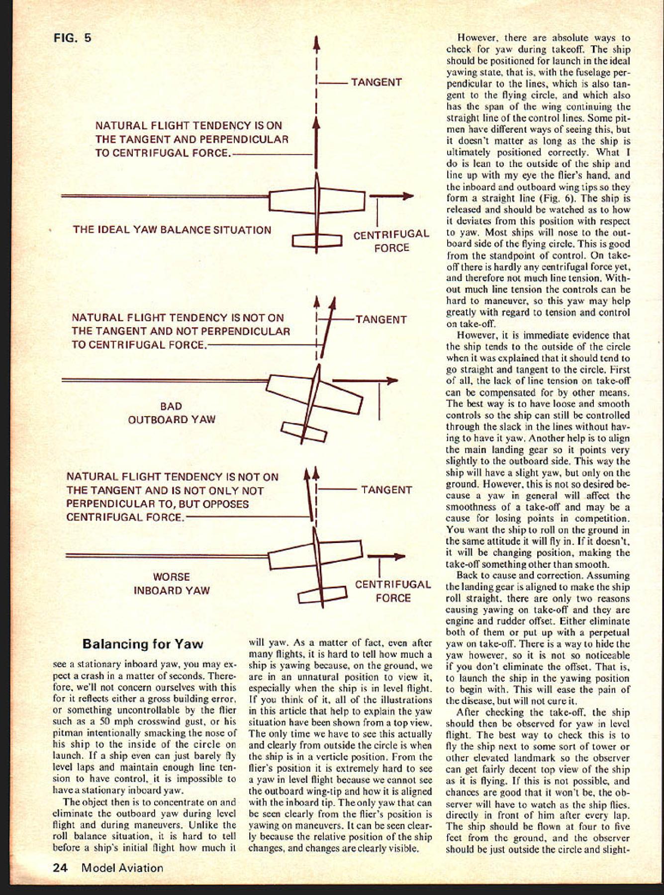
Chris Lella Although roll balancing covered last month complex form balancing Stunt Yaw problem probably misunderstood over-treated balance situation second three articles Balancing Yaw CL Stunt Ships LAST MONTH explained three axes plane covered detail bal ancing around longitudinal axis bal ancing roll article will ex plain balancing around vertical axis balancing yaw Induced Yaw Although roll balancing complex form balancing CL stunt flying regard trimming yaw problem probably misun derstood overtreated balance situa tion true two reasons First because unlike pitch roll always want certain amount yaw charac teristic ships keep line tension Second because very nature CL flying constantly has ships yawing ships always follow curved lateral path attitudes flight Because relentless circular path get centri fugal force major factor keeping tension want control lines Ill explain now Look path ship level flight Fig ship always has natural tendency travel straight line Because con nected control lines flier stationary center constant ly being pulled out straight line toward center result circu lar path tendency ship travel straight line what causes centrifugal force gives us desired tension lines Now centrifugal force maximized natural straight line flight thrust line must tangent flying circle perpendicular centri fugal force follows radius circle means engine rudder offset will cause natural line flight curved off tangent Conse quently will loss centrifugal force Since centrifugal force major factor keeping tension lines want tension lines left neat syllogism conclusion engine rudder offset unde sired can explained bit further purpose making bit clearer already mentioned because ship flies circular path constantly yawing Because centrifugal force causes desired tension lines maxi mized ships tendency fly straight line tangent flying circle must make ship fly tend ency Engine rudder offset will pro duce stationary outboard yaw tendency no longer straight line tan gent circle stationary out board yaw lose extra bit torque try hard get out en gines because thrust line being applied straight line flight tangent needed say engine rudder offset needed undesired June 1976 21 Ted Fancher original Moby Dick has downcurled wing tips pianotype hinging flippers flaps McCoy 40 power Roger Barretts 1975 Nats entry F-14 designed Macaluso distinctive twin fin rudder catches eyes flight FIG1 N N 4/ ACTUAL PATH SHIP FOLLOWS / CONTROL LINES PULLING SHIP AWAY FROM ITS STRAIGHT TENDENCY N N SHIP TENDS TO FLY STRAIGHT / / CENTRIFUGAL FORCE CAUSED / BYSHIPS / TENDENCY TO FLY ASTRAIGHT LINE KEEPS TENSION IN CONTROL LINES N ncing Yaw bit radical considering has univer sal building procedure long time Actually partially untrue must impress fact need stuntship yaw great what thought Most stunt fliers build ships intention having yaw have tension lines However need ship yaw keep line tension minutely present certain parts pattern Since centrifugal force major factor providing line tension yaw necessary lack centrifugal force specifically during maneuvers upper part flying hemisphere flying hemisphere area CL plane can possibly fly within limits yaw may needed because centrifugal force countered gravity causing loss line tension workable rudder came use hourglass hardest maneuvers correctly because tight inside corners must turned top flying hemisphere can easy loss line tension Without tension lines controls cannot pulled quickly enough yield sharp corner So Al Rabe devised linkage rudder moved provide outboard yaw down control pulled hence keeping tension lines top flying hemisphere also during outside part eights square eights also can tendency lose line tension Theoretically workable rudder cer tainly has merit know two stunt fliers have used great success Obviously however device completely limelight yet some thing has keeping line tension ships because have some nicely inscribed hourglasses na tional local skies combina tion things thing centrifugal force never completely lost zenith point directly above fliers head True diminished force gravity ship has enough power bring vertically through zenith noticeable change speed what level flight will main tain enough speed necessary keep line tension centrifugal force key word power stunt engine market capable maintaining neces sary stunt speed level flight However things separates good bad stunt engines ability maintain power during vertical flight engine stressed can compared high- low-torque auto mobile engines high-torque automobile engine will produce enough power main tain speed easily fairly steep upgrade low torque engine will car will deccelerate no matter much hit accelerator high-torque stunt engine will have sufficient power maintain speed during vertical flight thus have enough centrifugal force keep line tension top Before mentioned offset en gine will cause loss applicable torque Ill explain fully now since demon strated maximum torque necessary keep line tension engine offset thrust line tangent flying circle said necessary maximize centrifugal force Imagine ship connected control lines rear plane Fig 2 Ob viously would travel through flying circle because wouldnt would absolutely no centrifugal force Well engine offset normal fly ing setup actually approach set-up just imagined offset have closer hypo thetical ridiculous situation centrifugal force lose Fig 3 what meant loss applicable torque An engine can have lot tor que applied thrust line tangent flying circle torque will utilized may now question fact using engine offset using direct power engine create yaw would put tension lines using previous hypothetical setup would still obviously have tension directly engines thrust true fact remains centrifugal force nor mal stunt speeds would still put ten sion lines depended tension directly thrust en gine dont believe set up illustration Fig 2 actuality Start engine feel measure pull lines feel measure pull FIG 2 r EXPERIMENTAL AR RANGEMENT CONTROL LINES IF CONTROL LINES WERE ATTACHED TO SHIP IN THIS MAN NER TENSION IN LINES WOULD BE DIRECTLY FROM ENGINES THRUST AND WOULD NOT BE AS MUCH AS TENSION PRODUCED FROM CENTRIFUGAL FORCE AT NORMAL STUNT SPEEDS IN THE ACTUAL FLYING SETUP 22 Model Aviation j I NE & RUDDER OFFSET WILL E SHIP TO FLY WITH THIS \ //TENDENCY NOT TANGENT TO\\ 4 CIRCLE AND NOT PERPENDICULAR \ B / TO CENTRIFUGAL FORCE TANGENT TO FLYING CIRCLE~ SHIP SHOULD TEND TO FLY IN THIS LINE / CENTRIFUGAL / FORCE NOT / MAXIMIZED WITH / ENGINE AND / RUDDER OFFSET lines ship flying level laps will discover line tension caused centrifugal force Another contribution line tension side area fuselage fuselages ships also act airfoils ships top flying hemisphere side area significant factor keeping area spanning airfoil lift fuselages ships have air foil profiles consequently taller lift will yield top flying hemisphere Again line tension Now idea fuselage act ing airfoil idea deflected rudder rudder offset increasing lift airfoil logically follows Sure enough true deflected rudder will aid keeping line tension top flying hemisphere However permanently offset rudder per manent tendency yaw particularly level flight yaw undesirable rudder offset causing yaw thrust line automatically becomes offset tangent flying circle again lose applicable torque just mentioned wasting power manner also wast ing overcome drag created deflected surface should recall last months arti cle same disadvantage pres ent flap tweaking situation Remem ber Deflected surfaces should used ideally maneuver ship moment ship being maneuvered Use other time can help ful creates drag causes us lose efficiency respect power lift As far rudder concerned permanently deflected surface used indirectly maneuvering through upper part flying hemisphere has minor effect keeping line tension Therefore suggest permanent rudder offset used use no /8 et rudder 3-in root chord another adversity caused rudder offset obvious deflected rudder contemporary stuntship designs can cause inboard roll level flight outboard roll inverted flight Look standard verti cal tail surface section Fig 4 First notice vertical position CG ship take look vertical posi tion Center Pressure verti cal tail surfaces Center Pressure above CG deflected rudder pressure builds up result moment around vertical axis yaw also moment around longitudinal axis roll situation critical say warp certainly should consideration designing ulti mately clean ship summarizing section must mentioned whole concept induced yaw object keeping ten sion control lines point should done inducing tendency ship fly out cir cle pointing nose way stationary yaw created engine offset rudder offset Instead line tension should attained inducing tendency ship fly out circle fly ing through lateral axis said known maximizing centrifugal force Uninduced Yaw uninduced yaw mean imbalance will cause ship yaw unnecessarily undesirably such static dynamic aerody namic imbalances cause ship roll Engine rudder offset methods used intentionally cause yaw ever after building balancing processes ship can still have other physical characteristics causing yaw initially intended can hinder performance Ill start section explaining spe cifically what perfect yaw balance should Part inferred previous section induced yaw stuntship per fectly balanced yaw sum moments around vertical axis equal zero attitudes flight mo ments also explained last months article natural straight line flight tangent flying circle Fig 5 undesired yaw/ balance situation line flight off tangent toward inside flying circle inboard yaw As matter fact undesired balance situation around axis because im possible ship fly complete CL lap stationary inboard yaw FIG 4 CENTER OF PRESSURE CP OF VERTICAL TAIL SURFACE IS ABOVE CG CG N SIDE VIEW BECAUSE CP IS ABOVE CG DE FLECTED RUDDER WILL INDUCE FORCE CREATING ROLL MOMENT REAR VIEW OF TAIL SECTION June1976 23 FIG3 I 4 TANGENT NATURAL FLIGHT TENDENCY IS ON THE TANGENT AND PERPENDICULAR TO CENTRIFUGAL FORCE THE IDEAL YAW BALANCE SITUATION CENTRIFUGAL FORCE A11 TANG ENT NATURAL FLIGHT TENDENCY IS NOT ONI THE TANGENT AND NOT PERPENDICULARI TO CENTRIFUGAL FORCE1 BAD OUTBOARD YAW NATURAL FLIGHT TENDENCY IS NOT ON THE TANGENT AND IS NOT ONLY NOT PERPENDICULAR TO BUT OPPOSES CENTRIFUGAL FORCE WORSE INBOARD YAW Balancing Yaw see stationary inboard yaw may ex pect crash matter seconds fore well concern ourselves reflects either gross building error something uncontrollable flier such 50 mph crosswind gust pitman intentionally smacking nose ship inside circle launch ship can just barely fly level laps maintain enough line ten sion have control impossible have stationary inboard yaw object concentrate eliminate outboard yaw during level flight during maneuvers Unlike roll balance situation hard tell before ships initial flight much 4 \ i TANGENT CENTRIFUGAL FORCE will yaw As matter fact after flights hard tell much ship yawing because ground unnatural position view especially ship level flight think of illustrations article help explain yaw situation have shown top view time have see actually clearly outside circle ship verticle position fliers position extremely hard see yaw level flight because cannot see outboard wing-tip aligned inboard tip yaw can seen clearly fliers position yawing maneuvers can seen clear ly because relative position ship changes changes clearly visible However absolute ways check yaw during takeoff ship should positioned launch ideal yawing state fuselage per pendicular lines also tan gent flying circle also has span wing continuing straight line control lines Some pitmen have different ways seeing doesnt matter long ship ultimately positioned correctly What lean outside ship line up eye fliers hand inboard outboard wing tips form straight line Fig 6 ship released should watched deviates position respect yaw Most ships will nose out board side flying circle good standpoint control take off hardly centrifugal force yet therefore much line tension out much line tension controls can hard maneuver yaw may help greatly regard tension control take-off However immediate evidence ship tends outside circle explained should tend go straight tangent circle First lack line tension take-off can compensated other means best way have loose smooth controls ship can still controlled through slack lines hav ing have yaw Another help align main landing gear points very slightly outboard side way ship will have slight yaw ground However desired cause yaw general will affect smoothness take-off may cause losing points competition want ship roll ground same attitude will fly doesnt will changing position making take-off something other smooth Back cause correction Assuming landing gear aligned make ship roll straight two reasons causing yawing take-off engine rudder offset Either eliminate both put up perpetual yaw take-off way hide yaw however so noticeable dont eliminate offset launch ship yawing position begin will ease pain disease will cure After checking take-off ship should observed yaw level flight best way check fly ship next some sort tower other elevated landmark observer can get fairly decent top view ship flying possible chances good wont ob server will have watch ship flies directly front him after lap ship should flown four five feet ground observer should just outside circle slight24 Model Aviation FIG 5 AT LAUNCH PITMAN SHOULD HOLD SHIP IN POSITION WHERE THE FLYERS CONTROL HAND INBOARD AND OUTBOARD WINGTIPS FORM STRAIGHT LINE FIG 6 INBOARD YAW WORSE OUTBOARD NO YAW YAWBAD GOOD AS RESULT THE NATURAL LINE OF FLIGHT TENDENCY SHOULD BE TANGENT TO THE FLYING CIRCLE ly above would help stand ladder sit top car As ship comes around him should ideally positioned respect yaw exactly like first illustration Fig 5 two wing tips fliers hand should lie same line Dont line up wing tips control lines can done launch because lines will bow flight wing tips line up fliers hand youve got ship no yet apparent yawing charac teristics should have sufficient line tension However probably will case ship will likely have outboard yaw appear like second illustration Fig 5 Aside engine rudder offset being possible causes other possible cause improper longitudinal bal ance same principle im proper vertical balance causing roll Just explained Part verti cal position CG leadouts must have proper alignment avoid roll same reason longitudinal position CG leadouts must have proper alignment avoid yaw have ship fly tangent flying circle imaginary line connecting Iongitudinal position CG middle two leadouts must per pendicular fuselage As ship flying centrifugal force will cause CG leadout position lines lie straight line just picked rock up string string would straight ideal situation however its best mention just did principle can visualized actuality control lines bow induces inboard yawing moment So actually longitudinal leadout position should raked back bit compensate bowing lines Fig 7 best position leadouts hard calculate exactly because hard calculate longitudinal CG will lie also much lines will bow must done after observing ship flight especially after balancing pitch because nose-heavy tail-heavy ship will determine longitudinal CG. nose-heavy ship will have lon gitudinal CG further forward wing tail-heavy ship will have further back leadout position must aligned accordingly have just speaking IonFIG 7LONGITUDINAL CG IF THERE WAS NO AIR FRICTION CAUSING BOWING IN LINES THE LONGITUDINAL LEADOUT POSITION WOULD BE FAR UP c4D LONGITUDINAL CG IN ACTUALITY THERE IS BOWING SO IF LEADOUTS WERE WAY UP FRONT THERE WOULD BE TENDENCY FOR INBOARD YAWING LONGITUDINAL CG LEADOUTS RAKED BACK COMPENSATES FOR INBOARD YAWING CAUSED BY BOWING~ June 1976 25 FIG 8 IN LEVEL FLIGHT THERE IS EQUAL TENSION ON BOTH LINES AND POINT OF EFFECTIVE ATTACHMENT IS BETWEEN LEADOUTS POINT OF EFFECTIVE ATTACHMENT IS AT THE LEADOUT HOLE GUIDING THAT LINE WHEN CONTROL IS PULLED TO ITS MAXIMUM ALL TENSION AT THAT MOMENT IS ON ONE LINE II ILINE OF FLIGHT ITENDENCY OFF TANGENT OUTBOARD YAW CENTRIFUGAL CENTRIFUGAL FORCE OUTBOARD YAW Balancing Yaw gitudinal alignment leadout posi tion after stunt ship has flown would quite annoying leadouts permanently secured However still see lot cant help think because stunt ships flying unbalanced adjustable leadout guide came existence early Sixties surely helpful little invention Just chances great stunt ship cannot well bal anced aspect bench chances same stunt ship can never well balanced adjustable leadouts also think easier make install permanent leadouts Several latest ships have illustrated plans dont know make yet suggest tak ing look incorporating building procedure Youll find plans ship Sundance also plans Stunt Ma chine Genesis Sunshine mention few After yaw/balance situation level flight treated left per petual problem yawing occurs during maneuvers Yawing during maneu vers happens usually corners control pulled disappears right after controls neutralized can caused three reasons FIG 9 Shift tension up down control lines separated leadout position Usually up down leadouts separated least inch Consequently control pulled will tension line control instead equal tension both lines situation level flight Therefore effective leadout point attachment ship leadout hole guiding line Because lead outs spread apart longitudinally point attachment will change ten sion individual lines changes caused maneuvering controls control pulled its maximum tension moment line point effective attachment changes completely controls lead out hole centrifugal force will cause CG line up leadout yaw Fig 8 situation can seen clearly take ship separated leadouts further apart can seen hang leadouts having leadout hand Slowly release leadouts until ship hang ing just leadout should clearly see ship yaw same thing remaining leadout youll see ship yaw opposite direction Usually front leadout down control back leadout up control releasing down holding ship up leadout youll see outboard yaw releasing up holding ship down leadout youll see inboard yaw Keep mind stationary inboard yaw Youll see nose move inward relative will never stabilize position because down control never held maximum position long enough continued page 87 DURING LEVEL FLIGHT THERE IS CONSISTENT BOW AND THE TANGENT OF THE LINE OF TENSION AT LEADOUT POSITION IS CONSISTENT R FUGAL TANGENT OF LINE OF TENSION AT LEADOUT POSITION IF MANEUVER IS JERKED THE ARC OF THE BOW WILL BECOME SMALLER~ 4 I I II C G TANG ENT OF LINE TENSION AT LEADOUT POSITION WILL CHANGE WHEN BOW CHANGES CAUSING YAW CENTR FUGAL FORCE 26 Model Aviation WHOLE NEW LINE OF BIG WHEELS SMOOTH INFLATABLE building Big Ones res two piece hubs bolt together attached landing gear dura collar hidden between hub halves out side atever prefer Hub caps can used desired wheels can inflated deflated thru tiny valve side tire pressure desire J3 Cubs Aeroncas Sr Tele masters Mr Mulligans Twin Engine Cessnas etc Truly remarkable realistic looking wheel 400RDia. 450R4Y2 Dia. 500R5Dia. 550R51/2 Dia. 600R6 Dia. $795 Pr $995 Pr $1195 Pr oO 0%$1395 Pr $15 DU-BRO PRODUCTS DU 480 Bonner Road Wauconda Illinois 60084 USA Balancing Yaw/Lella continued page 26 retrospect now inboard yawing moment induced pulling down con trol cause ships have tendency lose line tension start outside maneuvers particularly sharp cor ners Think back hourglass now consider what youre up against loss speed also inboard yaw compounding things youre top flying hemisphere pop ping down control simple solution al though Bill Simons Ive seen problem simply resolved positioning up down leadout holes together no longitudinal separation Just leave about 1/32 1/16 between leadout holes leadouts wont twist inside ship 2 Change bow lines during flight Before mentioned ship would have tendency yaw board side caused bow lines Ill explain bit further now As ex plained longitudinal CG will line up lines leadouts bow tension lines straight curves lines curve however stops leadouts tension ship straight tan gent bow point leadouts aligned leadouts before compensate bow talk ing about consistent bow level flight during maneuvers bow changes becomes less some points others Therefore direction ten sion point leadouts will also change longitudinal CG will tend line up again tension Hence again will yawing Fig 9 no way eliminate prob lem because will always change tension bowing lines ever can minimized smooth control stick Any unneces sary jerking controls will cause yawing can also prove fly ing ship level flight As flying level jerk handle back forth out maneuvering controls Keep eye ship also have someone outside circle watch closely both should able see yawing Jerking handle may seem silly some fliers actually banging corner maneuver must popped must get come close rule book corner should done quick smooth pivot wrist arm As tension lines changes should follow tension fight other words ease tension toward ship cannot build up too radically decrease tension ease away ship cannot decrease too radically good example wingover maneuver first popped level flight arm should straight As ship comes overhead arm should bending compensating loss ten sion ship goes through top flying hemisphere As ship its descent arm should straightening out following increase tension p redo cue vie wp ro d u vxreviewprodu ctre viewp rod u ctre view P 47N Thunderbolt An add ton Top Fl te s well-known line Stand-off RC kitsP-51 P-40 P-39the P-47N spans 60 in. has 720 sq area takes 50 60 engines 4 6 channels Unique construction techniques reduce building time maintaining strong light structurally true airframe include formed balsa fuselage shells two-piece injected molded cowl full-length ma chined fuselage sides one-piece balsa ailerons flaps stabilizer Kit includes authentic fuelproof matte Mylwar pressure-sensitive decals hardware full-size plans illustrated step-bystep instruction booklet Top Flite Models Inc. 2638 S Wabash Ave. Chicago IL 60616 p red U vtrevge wp rvd U vtreviewprod uvtrevr ewprvdu etreview June 1976 87 PE RMAGLOSS COVERITE IS NOT PLASTIC made 100% polyester fibres behave differently plastic film cover ings Polyester easier apply lightweight never sags scratches flies better because its texture Try PermaGloss youll never use plastic again OEWETE 2779 Philmont Ave Huntingdon Valley Pa 19007 Yaw continued pullout pivot control handle Dont pull simultaneously lean bit turn ease line tension cause point line ten sion other point pattern SHIP IN VERTICAL FLIGHT FIG 10 ACTUAL\ 4 TANGENT TO FLIGHT PATH ii NATURAL FLIGHTjt] TENDENCY ii OFF TANGENT YAW EXCESSIVE TIP WEIGHT CAUSING YAW IN VERTICAL FLIGHT consequently greatest ten dency outboard yawing caused changing bow lines Remember Uniform line tension best assets stunt flier can have ship can usually will fly well because integral part ideal balance situation 3 Improper Lateral Balance takes affect vertical flight ship has too much too little tip weight commonly known affect roll situa tion However will also induce yaw vertical flight particularly coming level inverted flight vertical climb such wingover cause axes change relation grav ity level flight weight distribution lateral axis balanced around longitudinal axis vertical flight weight distribution lateral axis balanced around vertical axis fore inbalance too much little tip weight situation will cause mo ment around vertical axis known yawing ship perfectly balanced roll does follow will perfectly balanced yaw vertical flight re gard tip weight ultimately true tip weight balancing roll used counter aerodynamic im balance such too much lift outboard panel situation static imbalance tip weight offsetting aerodynamic imbalance excess lift outboard panel vertical flight aerodynamics change no lift situation Therefore tip weight becomes excess because being used counter opposite imbal ance So ship starts say wingover square excess tip weight will cause outboard yaw Fig 10 Unfortunately no static solu tion problem Removing tip weight would hinder roll/balance situa tion obvious solution aerodynamic Specifically must regress back problem attain ing ideal ratio inboard wing lift outboard wing lift problem re solved weight will have used advantage aerodynamic situa tion sacrifice its disadvantage another aerodynamic situation such problem just mentioned So concludes problem yaw Com pared roll surely obvious Also problems compounded because roll situation has two cleancut mediumslevel inverted flight ever yaw affects performing quality stunt ship critical Because best possible yaw situation precisely enabled control ships pitch through uniform tension way control lines ultimate ly thats definition very medium fly event flown Con trol Line Precision Aerobatics something understood reread think about what being said its still clear ask questions address 2850 E 196 St Bronx NY 10461 Fly Stunt Editors Note Concluding series articles next issue author discusses Balancing Pitch CL Scale/Stott continued page 28 strict calibration scale speeds ever adopted AMA would find would have build larger models full-sized aircraft flew higher rate speed would have build lighter achieve lighter wing load ing Lighter wing loadings will allow fly slower speed stalling See Chart #2 fact mind would limited larger lighter planes flew comparatively good speed feel would taking step backwards again restricting selection model down certain type aircraft January year some new rules proposed went effect concerning judging scale models Check column January-1976 issue Model Aviation complete list rule changes rules leveled out points given flying static judging purpose give type aircraft equal chance competition Quality quantity options should basic fundamental choosing best scale model way J-3 Cub has just good opportunity compet ing larger 4-engine bomber AMA would decide accept proposal tight emphasis actual scale flying speeds would backing up again limiting field selection scale models some cases would elimi nating altogether planes earlier eras classics address 118 East Wheeler St North Mankato MN 56001 88 Model Aviation productreviewproductreviewproductreview ,..Qi panese Tissue tissue light weight has goad covering characteristics Colors available red yellow orange blue green white Sheets 24 x 18 30 cents Complete catalogue 50 cents Peck Polymers Box 2498 LaMesa CA 92041 productreviewproductreviewproductreview

Edition: Model Aviation - 1976/06
Page Numbers: 21, 22, 23, 24, 25, 26, 87, 88

Edition: Model Aviation - 1976/06
Page Numbers: 21, 22, 23, 24, 25, 26, 87, 88
Chris Lella Although roll balancing covered last month complex form balancing Stunt Yaw problem probably misunderstood over-treated balance situation second three articles Balancing Yaw CL Stunt Ships LAST MONTH explained three axes plane covered detail bal ancing around longitudinal axis bal ancing roll article will ex plain balancing around vertical axis balancing yaw Induced Yaw Although roll balancing complex form balancing CL stunt flying regard trimming yaw problem probably misun derstood overtreated balance situa tion true two reasons First because unlike pitch roll always want certain amount yaw charac teristic ships keep line tension Second because very nature CL flying constantly has ships yawing ships always follow curved lateral path attitudes flight Because relentless circular path get centri fugal force major factor keeping tension want control lines Ill explain now Look path ship level flight Fig ship always has natural tendency travel straight line Because con nected control lines flier stationary center constant ly being pulled out straight line toward center result circu lar path tendency ship travel straight line what causes centrifugal force gives us desired tension lines Now centrifugal force maximized natural straight line flight thrust line must tangent flying circle perpendicular centri fugal force follows radius circle means engine rudder offset will cause natural line flight curved off tangent Conse quently will loss centrifugal force Since centrifugal force major factor keeping tension lines want tension lines left neat syllogism conclusion engine rudder offset unde sired can explained bit further purpose making bit clearer already mentioned because ship flies circular path constantly yawing Because centrifugal force causes desired tension lines maxi mized ships tendency fly straight line tangent flying circle must make ship fly tend ency Engine rudder offset will pro duce stationary outboard yaw tendency no longer straight line tan gent circle stationary out board yaw lose extra bit torque try hard get out en gines because thrust line being applied straight line flight tangent needed say engine rudder offset needed undesired June 1976 21 Ted Fancher original Moby Dick has downcurled wing tips pianotype hinging flippers flaps McCoy 40 power Roger Barretts 1975 Nats entry F-14 designed Macaluso distinctive twin fin rudder catches eyes flight FIG1 N N 4/ ACTUAL PATH SHIP FOLLOWS / CONTROL LINES PULLING SHIP AWAY FROM ITS STRAIGHT TENDENCY N N SHIP TENDS TO FLY STRAIGHT / / CENTRIFUGAL FORCE CAUSED / BYSHIPS / TENDENCY TO FLY ASTRAIGHT LINE KEEPS TENSION IN CONTROL LINES N ncing Yaw bit radical considering has univer sal building procedure long time Actually partially untrue must impress fact need stuntship yaw great what thought Most stunt fliers build ships intention having yaw have tension lines However need ship yaw keep line tension minutely present certain parts pattern Since centrifugal force major factor providing line tension yaw necessary lack centrifugal force specifically during maneuvers upper part flying hemisphere flying hemisphere area CL plane can possibly fly within limits yaw may needed because centrifugal force countered gravity causing loss line tension workable rudder came use hourglass hardest maneuvers correctly because tight inside corners must turned top flying hemisphere can easy loss line tension Without tension lines controls cannot pulled quickly enough yield sharp corner So Al Rabe devised linkage rudder moved provide outboard yaw down control pulled hence keeping tension lines top flying hemisphere also during outside part eights square eights also can tendency lose line tension Theoretically workable rudder cer tainly has merit know two stunt fliers have used great success Obviously however device completely limelight yet some thing has keeping line tension ships because have some nicely inscribed hourglasses na tional local skies combina tion things thing centrifugal force never completely lost zenith point directly above fliers head True diminished force gravity ship has enough power bring vertically through zenith noticeable change speed what level flight will main tain enough speed necessary keep line tension centrifugal force key word power stunt engine market capable maintaining neces sary stunt speed level flight However things separates good bad stunt engines ability maintain power during vertical flight engine stressed can compared high- low-torque auto mobile engines high-torque automobile engine will produce enough power main tain speed easily fairly steep upgrade low torque engine will car will deccelerate no matter much hit accelerator high-torque stunt engine will have sufficient power maintain speed during vertical flight thus have enough centrifugal force keep line tension top Before mentioned offset en gine will cause loss applicable torque Ill explain fully now since demon strated maximum torque necessary keep line tension engine offset thrust line tangent flying circle said necessary maximize centrifugal force Imagine ship connected control lines rear plane Fig 2 Ob viously would travel through flying circle because wouldnt would absolutely no centrifugal force Well engine offset normal fly ing setup actually approach set-up just imagined offset have closer hypo thetical ridiculous situation centrifugal force lose Fig 3 what meant loss applicable torque An engine can have lot tor que applied thrust line tangent flying circle torque will utilized may now question fact using engine offset using direct power engine create yaw would put tension lines using previous hypothetical setup would still obviously have tension directly engines thrust true fact remains centrifugal force nor mal stunt speeds would still put ten sion lines depended tension directly thrust en gine dont believe set up illustration Fig 2 actuality Start engine feel measure pull lines feel measure pull FIG 2 r EXPERIMENTAL AR RANGEMENT CONTROL LINES IF CONTROL LINES WERE ATTACHED TO SHIP IN THIS MAN NER TENSION IN LINES WOULD BE DIRECTLY FROM ENGINES THRUST AND WOULD NOT BE AS MUCH AS TENSION PRODUCED FROM CENTRIFUGAL FORCE AT NORMAL STUNT SPEEDS IN THE ACTUAL FLYING SETUP 22 Model Aviation j I NE & RUDDER OFFSET WILL E SHIP TO FLY WITH THIS \ //TENDENCY NOT TANGENT TO\\ 4 CIRCLE AND NOT PERPENDICULAR \ B / TO CENTRIFUGAL FORCE TANGENT TO FLYING CIRCLE~ SHIP SHOULD TEND TO FLY IN THIS LINE / CENTRIFUGAL / FORCE NOT / MAXIMIZED WITH / ENGINE AND / RUDDER OFFSET lines ship flying level laps will discover line tension caused centrifugal force Another contribution line tension side area fuselage fuselages ships also act airfoils ships top flying hemisphere side area significant factor keeping area spanning airfoil lift fuselages ships have air foil profiles consequently taller lift will yield top flying hemisphere Again line tension Now idea fuselage act ing airfoil idea deflected rudder rudder offset increasing lift airfoil logically follows Sure enough true deflected rudder will aid keeping line tension top flying hemisphere However permanently offset rudder per manent tendency yaw particularly level flight yaw undesirable rudder offset causing yaw thrust line automatically becomes offset tangent flying circle again lose applicable torque just mentioned wasting power manner also wast ing overcome drag created deflected surface should recall last months arti cle same disadvantage pres ent flap tweaking situation Remem ber Deflected surfaces should used ideally maneuver ship moment ship being maneuvered Use other time can help ful creates drag causes us lose efficiency respect power lift As far rudder concerned permanently deflected surface used indirectly maneuvering through upper part flying hemisphere has minor effect keeping line tension Therefore suggest permanent rudder offset used use no /8 et rudder 3-in root chord another adversity caused rudder offset obvious deflected rudder contemporary stuntship designs can cause inboard roll level flight outboard roll inverted flight Look standard verti cal tail surface section Fig 4 First notice vertical position CG ship take look vertical posi tion Center Pressure verti cal tail surfaces Center Pressure above CG deflected rudder pressure builds up result moment around vertical axis yaw also moment around longitudinal axis roll situation critical say warp certainly should consideration designing ulti mately clean ship summarizing section must mentioned whole concept induced yaw object keeping ten sion control lines point should done inducing tendency ship fly out cir cle pointing nose way stationary yaw created engine offset rudder offset Instead line tension should attained inducing tendency ship fly out circle fly ing through lateral axis said known maximizing centrifugal force Uninduced Yaw uninduced yaw mean imbalance will cause ship yaw unnecessarily undesirably such static dynamic aerody namic imbalances cause ship roll Engine rudder offset methods used intentionally cause yaw ever after building balancing processes ship can still have other physical characteristics causing yaw initially intended can hinder performance Ill start section explaining spe cifically what perfect yaw balance should Part inferred previous section induced yaw stuntship per fectly balanced yaw sum moments around vertical axis equal zero attitudes flight mo ments also explained last months article natural straight line flight tangent flying circle Fig 5 undesired yaw/ balance situation line flight off tangent toward inside flying circle inboard yaw As matter fact undesired balance situation around axis because im possible ship fly complete CL lap stationary inboard yaw FIG 4 CENTER OF PRESSURE CP OF VERTICAL TAIL SURFACE IS ABOVE CG CG N SIDE VIEW BECAUSE CP IS ABOVE CG DE FLECTED RUDDER WILL INDUCE FORCE CREATING ROLL MOMENT REAR VIEW OF TAIL SECTION June1976 23 FIG3 I 4 TANGENT NATURAL FLIGHT TENDENCY IS ON THE TANGENT AND PERPENDICULAR TO CENTRIFUGAL FORCE THE IDEAL YAW BALANCE SITUATION CENTRIFUGAL FORCE A11 TANG ENT NATURAL FLIGHT TENDENCY IS NOT ONI THE TANGENT AND NOT PERPENDICULARI TO CENTRIFUGAL FORCE1 BAD OUTBOARD YAW NATURAL FLIGHT TENDENCY IS NOT ON THE TANGENT AND IS NOT ONLY NOT PERPENDICULAR TO BUT OPPOSES CENTRIFUGAL FORCE WORSE INBOARD YAW Balancing Yaw see stationary inboard yaw may ex pect crash matter seconds fore well concern ourselves reflects either gross building error something uncontrollable flier such 50 mph crosswind gust pitman intentionally smacking nose ship inside circle launch ship can just barely fly level laps maintain enough line ten sion have control impossible have stationary inboard yaw object concentrate eliminate outboard yaw during level flight during maneuvers Unlike roll balance situation hard tell before ships initial flight much 4 \ i TANGENT CENTRIFUGAL FORCE will yaw As matter fact after flights hard tell much ship yawing because ground unnatural position view especially ship level flight think of illustrations article help explain yaw situation have shown top view time have see actually clearly outside circle ship verticle position fliers position extremely hard see yaw level flight because cannot see outboard wing-tip aligned inboard tip yaw can seen clearly fliers position yawing maneuvers can seen clear ly because relative position ship changes changes clearly visible However absolute ways check yaw during takeoff ship should positioned launch ideal yawing state fuselage per pendicular lines also tan gent flying circle also has span wing continuing straight line control lines Some pitmen have different ways seeing doesnt matter long ship ultimately positioned correctly What lean outside ship line up eye fliers hand inboard outboard wing tips form straight line Fig 6 ship released should watched deviates position respect yaw Most ships will nose out board side flying circle good standpoint control take off hardly centrifugal force yet therefore much line tension out much line tension controls can hard maneuver yaw may help greatly regard tension control take-off However immediate evidence ship tends outside circle explained should tend go straight tangent circle First lack line tension take-off can compensated other means best way have loose smooth controls ship can still controlled through slack lines hav ing have yaw Another help align main landing gear points very slightly outboard side way ship will have slight yaw ground However desired cause yaw general will affect smoothness take-off may cause losing points competition want ship roll ground same attitude will fly doesnt will changing position making take-off something other smooth Back cause correction Assuming landing gear aligned make ship roll straight two reasons causing yawing take-off engine rudder offset Either eliminate both put up perpetual yaw take-off way hide yaw however so noticeable dont eliminate offset launch ship yawing position begin will ease pain disease will cure After checking take-off ship should observed yaw level flight best way check fly ship next some sort tower other elevated landmark observer can get fairly decent top view ship flying possible chances good wont ob server will have watch ship flies directly front him after lap ship should flown four five feet ground observer should just outside circle slight24 Model Aviation FIG 5 AT LAUNCH PITMAN SHOULD HOLD SHIP IN POSITION WHERE THE FLYERS CONTROL HAND INBOARD AND OUTBOARD WINGTIPS FORM STRAIGHT LINE FIG 6 INBOARD YAW WORSE OUTBOARD NO YAW YAWBAD GOOD AS RESULT THE NATURAL LINE OF FLIGHT TENDENCY SHOULD BE TANGENT TO THE FLYING CIRCLE ly above would help stand ladder sit top car As ship comes around him should ideally positioned respect yaw exactly like first illustration Fig 5 two wing tips fliers hand should lie same line Dont line up wing tips control lines can done launch because lines will bow flight wing tips line up fliers hand youve got ship no yet apparent yawing charac teristics should have sufficient line tension However probably will case ship will likely have outboard yaw appear like second illustration Fig 5 Aside engine rudder offset being possible causes other possible cause improper longitudinal bal ance same principle im proper vertical balance causing roll Just explained Part verti cal position CG leadouts must have proper alignment avoid roll same reason longitudinal position CG leadouts must have proper alignment avoid yaw have ship fly tangent flying circle imaginary line connecting Iongitudinal position CG middle two leadouts must per pendicular fuselage As ship flying centrifugal force will cause CG leadout position lines lie straight line just picked rock up string string would straight ideal situation however its best mention just did principle can visualized actuality control lines bow induces inboard yawing moment So actually longitudinal leadout position should raked back bit compensate bowing lines Fig 7 best position leadouts hard calculate exactly because hard calculate longitudinal CG will lie also much lines will bow must done after observing ship flight especially after balancing pitch because nose-heavy tail-heavy ship will determine longitudinal CG. nose-heavy ship will have lon gitudinal CG further forward wing tail-heavy ship will have further back leadout position must aligned accordingly have just speaking IonFIG 7LONGITUDINAL CG IF THERE WAS NO AIR FRICTION CAUSING BOWING IN LINES THE LONGITUDINAL LEADOUT POSITION WOULD BE FAR UP c4D LONGITUDINAL CG IN ACTUALITY THERE IS BOWING SO IF LEADOUTS WERE WAY UP FRONT THERE WOULD BE TENDENCY FOR INBOARD YAWING LONGITUDINAL CG LEADOUTS RAKED BACK COMPENSATES FOR INBOARD YAWING CAUSED BY BOWING~ June 1976 25 FIG 8 IN LEVEL FLIGHT THERE IS EQUAL TENSION ON BOTH LINES AND POINT OF EFFECTIVE ATTACHMENT IS BETWEEN LEADOUTS POINT OF EFFECTIVE ATTACHMENT IS AT THE LEADOUT HOLE GUIDING THAT LINE WHEN CONTROL IS PULLED TO ITS MAXIMUM ALL TENSION AT THAT MOMENT IS ON ONE LINE II ILINE OF FLIGHT ITENDENCY OFF TANGENT OUTBOARD YAW CENTRIFUGAL CENTRIFUGAL FORCE OUTBOARD YAW Balancing Yaw gitudinal alignment leadout posi tion after stunt ship has flown would quite annoying leadouts permanently secured However still see lot cant help think because stunt ships flying unbalanced adjustable leadout guide came existence early Sixties surely helpful little invention Just chances great stunt ship cannot well bal anced aspect bench chances same stunt ship can never well balanced adjustable leadouts also think easier make install permanent leadouts Several latest ships have illustrated plans dont know make yet suggest tak ing look incorporating building procedure Youll find plans ship Sundance also plans Stunt Ma chine Genesis Sunshine mention few After yaw/balance situation level flight treated left per petual problem yawing occurs during maneuvers Yawing during maneu vers happens usually corners control pulled disappears right after controls neutralized can caused three reasons FIG 9 Shift tension up down control lines separated leadout position Usually up down leadouts separated least inch Consequently control pulled will tension line control instead equal tension both lines situation level flight Therefore effective leadout point attachment ship leadout hole guiding line Because lead outs spread apart longitudinally point attachment will change ten sion individual lines changes caused maneuvering controls control pulled its maximum tension moment line point effective attachment changes completely controls lead out hole centrifugal force will cause CG line up leadout yaw Fig 8 situation can seen clearly take ship separated leadouts further apart can seen hang leadouts having leadout hand Slowly release leadouts until ship hang ing just leadout should clearly see ship yaw same thing remaining leadout youll see ship yaw opposite direction Usually front leadout down control back leadout up control releasing down holding ship up leadout youll see outboard yaw releasing up holding ship down leadout youll see inboard yaw Keep mind stationary inboard yaw Youll see nose move inward relative will never stabilize position because down control never held maximum position long enough continued page 87 DURING LEVEL FLIGHT THERE IS CONSISTENT BOW AND THE TANGENT OF THE LINE OF TENSION AT LEADOUT POSITION IS CONSISTENT R FUGAL TANGENT OF LINE OF TENSION AT LEADOUT POSITION IF MANEUVER IS JERKED THE ARC OF THE BOW WILL BECOME SMALLER~ 4 I I II C G TANG ENT OF LINE TENSION AT LEADOUT POSITION WILL CHANGE WHEN BOW CHANGES CAUSING YAW CENTR FUGAL FORCE 26 Model Aviation WHOLE NEW LINE OF BIG WHEELS SMOOTH INFLATABLE building Big Ones res two piece hubs bolt together attached landing gear dura collar hidden between hub halves out side atever prefer Hub caps can used desired wheels can inflated deflated thru tiny valve side tire pressure desire J3 Cubs Aeroncas Sr Tele masters Mr Mulligans Twin Engine Cessnas etc Truly remarkable realistic looking wheel 400RDia. 450R4Y2 Dia. 500R5Dia. 550R51/2 Dia. 600R6 Dia. $795 Pr $995 Pr $1195 Pr oO 0%$1395 Pr $15 DU-BRO PRODUCTS DU 480 Bonner Road Wauconda Illinois 60084 USA Balancing Yaw/Lella continued page 26 retrospect now inboard yawing moment induced pulling down con trol cause ships have tendency lose line tension start outside maneuvers particularly sharp cor ners Think back hourglass now consider what youre up against loss speed also inboard yaw compounding things youre top flying hemisphere pop ping down control simple solution al though Bill Simons Ive seen problem simply resolved positioning up down leadout holes together no longitudinal separation Just leave about 1/32 1/16 between leadout holes leadouts wont twist inside ship 2 Change bow lines during flight Before mentioned ship would have tendency yaw board side caused bow lines Ill explain bit further now As ex plained longitudinal CG will line up lines leadouts bow tension lines straight curves lines curve however stops leadouts tension ship straight tan gent bow point leadouts aligned leadouts before compensate bow talk ing about consistent bow level flight during maneuvers bow changes becomes less some points others Therefore direction ten sion point leadouts will also change longitudinal CG will tend line up again tension Hence again will yawing Fig 9 no way eliminate prob lem because will always change tension bowing lines ever can minimized smooth control stick Any unneces sary jerking controls will cause yawing can also prove fly ing ship level flight As flying level jerk handle back forth out maneuvering controls Keep eye ship also have someone outside circle watch closely both should able see yawing Jerking handle may seem silly some fliers actually banging corner maneuver must popped must get come close rule book corner should done quick smooth pivot wrist arm As tension lines changes should follow tension fight other words ease tension toward ship cannot build up too radically decrease tension ease away ship cannot decrease too radically good example wingover maneuver first popped level flight arm should straight As ship comes overhead arm should bending compensating loss ten sion ship goes through top flying hemisphere As ship its descent arm should straightening out following increase tension p redo cue vie wp ro d u vxreviewprodu ctre viewp rod u ctre view P 47N Thunderbolt An add ton Top Fl te s well-known line Stand-off RC kitsP-51 P-40 P-39the P-47N spans 60 in. has 720 sq area takes 50 60 engines 4 6 channels Unique construction techniques reduce building time maintaining strong light structurally true airframe include formed balsa fuselage shells two-piece injected molded cowl full-length ma chined fuselage sides one-piece balsa ailerons flaps stabilizer Kit includes authentic fuelproof matte Mylwar pressure-sensitive decals hardware full-size plans illustrated step-bystep instruction booklet Top Flite Models Inc. 2638 S Wabash Ave. Chicago IL 60616 p red U vtrevge wp rvd U vtreviewprod uvtrevr ewprvdu etreview June 1976 87 PE RMAGLOSS COVERITE IS NOT PLASTIC made 100% polyester fibres behave differently plastic film cover ings Polyester easier apply lightweight never sags scratches flies better because its texture Try PermaGloss youll never use plastic again OEWETE 2779 Philmont Ave Huntingdon Valley Pa 19007 Yaw continued pullout pivot control handle Dont pull simultaneously lean bit turn ease line tension cause point line ten sion other point pattern SHIP IN VERTICAL FLIGHT FIG 10 ACTUAL\ 4 TANGENT TO FLIGHT PATH ii NATURAL FLIGHTjt] TENDENCY ii OFF TANGENT YAW EXCESSIVE TIP WEIGHT CAUSING YAW IN VERTICAL FLIGHT consequently greatest ten dency outboard yawing caused changing bow lines Remember Uniform line tension best assets stunt flier can have ship can usually will fly well because integral part ideal balance situation 3 Improper Lateral Balance takes affect vertical flight ship has too much too little tip weight commonly known affect roll situa tion However will also induce yaw vertical flight particularly coming level inverted flight vertical climb such wingover cause axes change relation grav ity level flight weight distribution lateral axis balanced around longitudinal axis vertical flight weight distribution lateral axis balanced around vertical axis fore inbalance too much little tip weight situation will cause mo ment around vertical axis known yawing ship perfectly balanced roll does follow will perfectly balanced yaw vertical flight re gard tip weight ultimately true tip weight balancing roll used counter aerodynamic im balance such too much lift outboard panel situation static imbalance tip weight offsetting aerodynamic imbalance excess lift outboard panel vertical flight aerodynamics change no lift situation Therefore tip weight becomes excess because being used counter opposite imbal ance So ship starts say wingover square excess tip weight will cause outboard yaw Fig 10 Unfortunately no static solu tion problem Removing tip weight would hinder roll/balance situa tion obvious solution aerodynamic Specifically must regress back problem attain ing ideal ratio inboard wing lift outboard wing lift problem re solved weight will have used advantage aerodynamic situa tion sacrifice its disadvantage another aerodynamic situation such problem just mentioned So concludes problem yaw Com pared roll surely obvious Also problems compounded because roll situation has two cleancut mediumslevel inverted flight ever yaw affects performing quality stunt ship critical Because best possible yaw situation precisely enabled control ships pitch through uniform tension way control lines ultimate ly thats definition very medium fly event flown Con trol Line Precision Aerobatics something understood reread think about what being said its still clear ask questions address 2850 E 196 St Bronx NY 10461 Fly Stunt Editors Note Concluding series articles next issue author discusses Balancing Pitch CL Scale/Stott continued page 28 strict calibration scale speeds ever adopted AMA would find would have build larger models full-sized aircraft flew higher rate speed would have build lighter achieve lighter wing load ing Lighter wing loadings will allow fly slower speed stalling See Chart #2 fact mind would limited larger lighter planes flew comparatively good speed feel would taking step backwards again restricting selection model down certain type aircraft January year some new rules proposed went effect concerning judging scale models Check column January-1976 issue Model Aviation complete list rule changes rules leveled out points given flying static judging purpose give type aircraft equal chance competition Quality quantity options should basic fundamental choosing best scale model way J-3 Cub has just good opportunity compet ing larger 4-engine bomber AMA would decide accept proposal tight emphasis actual scale flying speeds would backing up again limiting field selection scale models some cases would elimi nating altogether planes earlier eras classics address 118 East Wheeler St North Mankato MN 56001 88 Model Aviation productreviewproductreviewproductreview ,..Qi panese Tissue tissue light weight has goad covering characteristics Colors available red yellow orange blue green white Sheets 24 x 18 30 cents Complete catalogue 50 cents Peck Polymers Box 2498 LaMesa CA 92041 productreviewproductreviewproductreview

Edition: Model Aviation - 1976/06
Page Numbers: 21, 22, 23, 24, 25, 26, 87, 88
Chris Lella Although roll balancing covered last month complex form balancing Stunt Yaw problem probably misunderstood over-treated balance situation second three articles Balancing Yaw CL Stunt Ships LAST MONTH explained three axes plane covered detail bal ancing around longitudinal axis bal ancing roll article will ex plain balancing around vertical axis balancing yaw Induced Yaw Although roll balancing complex form balancing CL stunt flying regard trimming yaw problem probably misun derstood overtreated balance situa tion true two reasons First because unlike pitch roll always want certain amount yaw charac teristic ships keep line tension Second because very nature CL flying constantly has ships yawing ships always follow curved lateral path attitudes flight Because relentless circular path get centri fugal force major factor keeping tension want control lines Ill explain now Look path ship level flight Fig ship always has natural tendency travel straight line Because con nected control lines flier stationary center constant ly being pulled out straight line toward center result circu lar path tendency ship travel straight line what causes centrifugal force gives us desired tension lines Now centrifugal force maximized natural straight line flight thrust line must tangent flying circle perpendicular centri fugal force follows radius circle means engine rudder offset will cause natural line flight curved off tangent Conse quently will loss centrifugal force Since centrifugal force major factor keeping tension lines want tension lines left neat syllogism conclusion engine rudder offset unde sired can explained bit further purpose making bit clearer already mentioned because ship flies circular path constantly yawing Because centrifugal force causes desired tension lines maxi mized ships tendency fly straight line tangent flying circle must make ship fly tend ency Engine rudder offset will pro duce stationary outboard yaw tendency no longer straight line tan gent circle stationary out board yaw lose extra bit torque try hard get out en gines because thrust line being applied straight line flight tangent needed say engine rudder offset needed undesired June 1976 21 Ted Fancher original Moby Dick has downcurled wing tips pianotype hinging flippers flaps McCoy 40 power Roger Barretts 1975 Nats entry F-14 designed Macaluso distinctive twin fin rudder catches eyes flight FIG1 N N 4/ ACTUAL PATH SHIP FOLLOWS / CONTROL LINES PULLING SHIP AWAY FROM ITS STRAIGHT TENDENCY N N SHIP TENDS TO FLY STRAIGHT / / CENTRIFUGAL FORCE CAUSED / BYSHIPS / TENDENCY TO FLY ASTRAIGHT LINE KEEPS TENSION IN CONTROL LINES N ncing Yaw bit radical considering has univer sal building procedure long time Actually partially untrue must impress fact need stuntship yaw great what thought Most stunt fliers build ships intention having yaw have tension lines However need ship yaw keep line tension minutely present certain parts pattern Since centrifugal force major factor providing line tension yaw necessary lack centrifugal force specifically during maneuvers upper part flying hemisphere flying hemisphere area CL plane can possibly fly within limits yaw may needed because centrifugal force countered gravity causing loss line tension workable rudder came use hourglass hardest maneuvers correctly because tight inside corners must turned top flying hemisphere can easy loss line tension Without tension lines controls cannot pulled quickly enough yield sharp corner So Al Rabe devised linkage rudder moved provide outboard yaw down control pulled hence keeping tension lines top flying hemisphere also during outside part eights square eights also can tendency lose line tension Theoretically workable rudder cer tainly has merit know two stunt fliers have used great success Obviously however device completely limelight yet some thing has keeping line tension ships because have some nicely inscribed hourglasses na tional local skies combina tion things thing centrifugal force never completely lost zenith point directly above fliers head True diminished force gravity ship has enough power bring vertically through zenith noticeable change speed what level flight will main tain enough speed necessary keep line tension centrifugal force key word power stunt engine market capable maintaining neces sary stunt speed level flight However things separates good bad stunt engines ability maintain power during vertical flight engine stressed can compared high- low-torque auto mobile engines high-torque automobile engine will produce enough power main tain speed easily fairly steep upgrade low torque engine will car will deccelerate no matter much hit accelerator high-torque stunt engine will have sufficient power maintain speed during vertical flight thus have enough centrifugal force keep line tension top Before mentioned offset en gine will cause loss applicable torque Ill explain fully now since demon strated maximum torque necessary keep line tension engine offset thrust line tangent flying circle said necessary maximize centrifugal force Imagine ship connected control lines rear plane Fig 2 Ob viously would travel through flying circle because wouldnt would absolutely no centrifugal force Well engine offset normal fly ing setup actually approach set-up just imagined offset have closer hypo thetical ridiculous situation centrifugal force lose Fig 3 what meant loss applicable torque An engine can have lot tor que applied thrust line tangent flying circle torque will utilized may now question fact using engine offset using direct power engine create yaw would put tension lines using previous hypothetical setup would still obviously have tension directly engines thrust true fact remains centrifugal force nor mal stunt speeds would still put ten sion lines depended tension directly thrust en gine dont believe set up illustration Fig 2 actuality Start engine feel measure pull lines feel measure pull FIG 2 r EXPERIMENTAL AR RANGEMENT CONTROL LINES IF CONTROL LINES WERE ATTACHED TO SHIP IN THIS MAN NER TENSION IN LINES WOULD BE DIRECTLY FROM ENGINES THRUST AND WOULD NOT BE AS MUCH AS TENSION PRODUCED FROM CENTRIFUGAL FORCE AT NORMAL STUNT SPEEDS IN THE ACTUAL FLYING SETUP 22 Model Aviation j I NE & RUDDER OFFSET WILL E SHIP TO FLY WITH THIS \ //TENDENCY NOT TANGENT TO\\ 4 CIRCLE AND NOT PERPENDICULAR \ B / TO CENTRIFUGAL FORCE TANGENT TO FLYING CIRCLE~ SHIP SHOULD TEND TO FLY IN THIS LINE / CENTRIFUGAL / FORCE NOT / MAXIMIZED WITH / ENGINE AND / RUDDER OFFSET lines ship flying level laps will discover line tension caused centrifugal force Another contribution line tension side area fuselage fuselages ships also act airfoils ships top flying hemisphere side area significant factor keeping area spanning airfoil lift fuselages ships have air foil profiles consequently taller lift will yield top flying hemisphere Again line tension Now idea fuselage act ing airfoil idea deflected rudder rudder offset increasing lift airfoil logically follows Sure enough true deflected rudder will aid keeping line tension top flying hemisphere However permanently offset rudder per manent tendency yaw particularly level flight yaw undesirable rudder offset causing yaw thrust line automatically becomes offset tangent flying circle again lose applicable torque just mentioned wasting power manner also wast ing overcome drag created deflected surface should recall last months arti cle same disadvantage pres ent flap tweaking situation Remem ber Deflected surfaces should used ideally maneuver ship moment ship being maneuvered Use other time can help ful creates drag causes us lose efficiency respect power lift As far rudder concerned permanently deflected surface used indirectly maneuvering through upper part flying hemisphere has minor effect keeping line tension Therefore suggest permanent rudder offset used use no /8 et rudder 3-in root chord another adversity caused rudder offset obvious deflected rudder contemporary stuntship designs can cause inboard roll level flight outboard roll inverted flight Look standard verti cal tail surface section Fig 4 First notice vertical position CG ship take look vertical posi tion Center Pressure verti cal tail surfaces Center Pressure above CG deflected rudder pressure builds up result moment around vertical axis yaw also moment around longitudinal axis roll situation critical say warp certainly should consideration designing ulti mately clean ship summarizing section must mentioned whole concept induced yaw object keeping ten sion control lines point should done inducing tendency ship fly out cir cle pointing nose way stationary yaw created engine offset rudder offset Instead line tension should attained inducing tendency ship fly out circle fly ing through lateral axis said known maximizing centrifugal force Uninduced Yaw uninduced yaw mean imbalance will cause ship yaw unnecessarily undesirably such static dynamic aerody namic imbalances cause ship roll Engine rudder offset methods used intentionally cause yaw ever after building balancing processes ship can still have other physical characteristics causing yaw initially intended can hinder performance Ill start section explaining spe cifically what perfect yaw balance should Part inferred previous section induced yaw stuntship per fectly balanced yaw sum moments around vertical axis equal zero attitudes flight mo ments also explained last months article natural straight line flight tangent flying circle Fig 5 undesired yaw/ balance situation line flight off tangent toward inside flying circle inboard yaw As matter fact undesired balance situation around axis because im possible ship fly complete CL lap stationary inboard yaw FIG 4 CENTER OF PRESSURE CP OF VERTICAL TAIL SURFACE IS ABOVE CG CG N SIDE VIEW BECAUSE CP IS ABOVE CG DE FLECTED RUDDER WILL INDUCE FORCE CREATING ROLL MOMENT REAR VIEW OF TAIL SECTION June1976 23 FIG3 I 4 TANGENT NATURAL FLIGHT TENDENCY IS ON THE TANGENT AND PERPENDICULAR TO CENTRIFUGAL FORCE THE IDEAL YAW BALANCE SITUATION CENTRIFUGAL FORCE A11 TANG ENT NATURAL FLIGHT TENDENCY IS NOT ONI THE TANGENT AND NOT PERPENDICULARI TO CENTRIFUGAL FORCE1 BAD OUTBOARD YAW NATURAL FLIGHT TENDENCY IS NOT ON THE TANGENT AND IS NOT ONLY NOT PERPENDICULAR TO BUT OPPOSES CENTRIFUGAL FORCE WORSE INBOARD YAW Balancing Yaw see stationary inboard yaw may ex pect crash matter seconds fore well concern ourselves reflects either gross building error something uncontrollable flier such 50 mph crosswind gust pitman intentionally smacking nose ship inside circle launch ship can just barely fly level laps maintain enough line ten sion have control impossible have stationary inboard yaw object concentrate eliminate outboard yaw during level flight during maneuvers Unlike roll balance situation hard tell before ships initial flight much 4 \ i TANGENT CENTRIFUGAL FORCE will yaw As matter fact after flights hard tell much ship yawing because ground unnatural position view especially ship level flight think of illustrations article help explain yaw situation have shown top view time have see actually clearly outside circle ship verticle position fliers position extremely hard see yaw level flight because cannot see outboard wing-tip aligned inboard tip yaw can seen clearly fliers position yawing maneuvers can seen clear ly because relative position ship changes changes clearly visible However absolute ways check yaw during takeoff ship should positioned launch ideal yawing state fuselage per pendicular lines also tan gent flying circle also has span wing continuing straight line control lines Some pitmen have different ways seeing doesnt matter long ship ultimately positioned correctly What lean outside ship line up eye fliers hand inboard outboard wing tips form straight line Fig 6 ship released should watched deviates position respect yaw Most ships will nose out board side flying circle good standpoint control take off hardly centrifugal force yet therefore much line tension out much line tension controls can hard maneuver yaw may help greatly regard tension control take-off However immediate evidence ship tends outside circle explained should tend go straight tangent circle First lack line tension take-off can compensated other means best way have loose smooth controls ship can still controlled through slack lines hav ing have yaw Another help align main landing gear points very slightly outboard side way ship will have slight yaw ground However desired cause yaw general will affect smoothness take-off may cause losing points competition want ship roll ground same attitude will fly doesnt will changing position making take-off something other smooth Back cause correction Assuming landing gear aligned make ship roll straight two reasons causing yawing take-off engine rudder offset Either eliminate both put up perpetual yaw take-off way hide yaw however so noticeable dont eliminate offset launch ship yawing position begin will ease pain disease will cure After checking take-off ship should observed yaw level flight best way check fly ship next some sort tower other elevated landmark observer can get fairly decent top view ship flying possible chances good wont ob server will have watch ship flies directly front him after lap ship should flown four five feet ground observer should just outside circle slight24 Model Aviation FIG 5 AT LAUNCH PITMAN SHOULD HOLD SHIP IN POSITION WHERE THE FLYERS CONTROL HAND INBOARD AND OUTBOARD WINGTIPS FORM STRAIGHT LINE FIG 6 INBOARD YAW WORSE OUTBOARD NO YAW YAWBAD GOOD AS RESULT THE NATURAL LINE OF FLIGHT TENDENCY SHOULD BE TANGENT TO THE FLYING CIRCLE ly above would help stand ladder sit top car As ship comes around him should ideally positioned respect yaw exactly like first illustration Fig 5 two wing tips fliers hand should lie same line Dont line up wing tips control lines can done launch because lines will bow flight wing tips line up fliers hand youve got ship no yet apparent yawing charac teristics should have sufficient line tension However probably will case ship will likely have outboard yaw appear like second illustration Fig 5 Aside engine rudder offset being possible causes other possible cause improper longitudinal bal ance same principle im proper vertical balance causing roll Just explained Part verti cal position CG leadouts must have proper alignment avoid roll same reason longitudinal position CG leadouts must have proper alignment avoid yaw have ship fly tangent flying circle imaginary line connecting Iongitudinal position CG middle two leadouts must per pendicular fuselage As ship flying centrifugal force will cause CG leadout position lines lie straight line just picked rock up string string would straight ideal situation however its best mention just did principle can visualized actuality control lines bow induces inboard yawing moment So actually longitudinal leadout position should raked back bit compensate bowing lines Fig 7 best position leadouts hard calculate exactly because hard calculate longitudinal CG will lie also much lines will bow must done after observing ship flight especially after balancing pitch because nose-heavy tail-heavy ship will determine longitudinal CG. nose-heavy ship will have lon gitudinal CG further forward wing tail-heavy ship will have further back leadout position must aligned accordingly have just speaking IonFIG 7LONGITUDINAL CG IF THERE WAS NO AIR FRICTION CAUSING BOWING IN LINES THE LONGITUDINAL LEADOUT POSITION WOULD BE FAR UP c4D LONGITUDINAL CG IN ACTUALITY THERE IS BOWING SO IF LEADOUTS WERE WAY UP FRONT THERE WOULD BE TENDENCY FOR INBOARD YAWING LONGITUDINAL CG LEADOUTS RAKED BACK COMPENSATES FOR INBOARD YAWING CAUSED BY BOWING~ June 1976 25 FIG 8 IN LEVEL FLIGHT THERE IS EQUAL TENSION ON BOTH LINES AND POINT OF EFFECTIVE ATTACHMENT IS BETWEEN LEADOUTS POINT OF EFFECTIVE ATTACHMENT IS AT THE LEADOUT HOLE GUIDING THAT LINE WHEN CONTROL IS PULLED TO ITS MAXIMUM ALL TENSION AT THAT MOMENT IS ON ONE LINE II ILINE OF FLIGHT ITENDENCY OFF TANGENT OUTBOARD YAW CENTRIFUGAL CENTRIFUGAL FORCE OUTBOARD YAW Balancing Yaw gitudinal alignment leadout posi tion after stunt ship has flown would quite annoying leadouts permanently secured However still see lot cant help think because stunt ships flying unbalanced adjustable leadout guide came existence early Sixties surely helpful little invention Just chances great stunt ship cannot well bal anced aspect bench chances same stunt ship can never well balanced adjustable leadouts also think easier make install permanent leadouts Several latest ships have illustrated plans dont know make yet suggest tak ing look incorporating building procedure Youll find plans ship Sundance also plans Stunt Ma chine Genesis Sunshine mention few After yaw/balance situation level flight treated left per petual problem yawing occurs during maneuvers Yawing during maneu vers happens usually corners control pulled disappears right after controls neutralized can caused three reasons FIG 9 Shift tension up down control lines separated leadout position Usually up down leadouts separated least inch Consequently control pulled will tension line control instead equal tension both lines situation level flight Therefore effective leadout point attachment ship leadout hole guiding line Because lead outs spread apart longitudinally point attachment will change ten sion individual lines changes caused maneuvering controls control pulled its maximum tension moment line point effective attachment changes completely controls lead out hole centrifugal force will cause CG line up leadout yaw Fig 8 situation can seen clearly take ship separated leadouts further apart can seen hang leadouts having leadout hand Slowly release leadouts until ship hang ing just leadout should clearly see ship yaw same thing remaining leadout youll see ship yaw opposite direction Usually front leadout down control back leadout up control releasing down holding ship up leadout youll see outboard yaw releasing up holding ship down leadout youll see inboard yaw Keep mind stationary inboard yaw Youll see nose move inward relative will never stabilize position because down control never held maximum position long enough continued page 87 DURING LEVEL FLIGHT THERE IS CONSISTENT BOW AND THE TANGENT OF THE LINE OF TENSION AT LEADOUT POSITION IS CONSISTENT R FUGAL TANGENT OF LINE OF TENSION AT LEADOUT POSITION IF MANEUVER IS JERKED THE ARC OF THE BOW WILL BECOME SMALLER~ 4 I I II C G TANG ENT OF LINE TENSION AT LEADOUT POSITION WILL CHANGE WHEN BOW CHANGES CAUSING YAW CENTR FUGAL FORCE 26 Model Aviation WHOLE NEW LINE OF BIG WHEELS SMOOTH INFLATABLE building Big Ones res two piece hubs bolt together attached landing gear dura collar hidden between hub halves out side atever prefer Hub caps can used desired wheels can inflated deflated thru tiny valve side tire pressure desire J3 Cubs Aeroncas Sr Tele masters Mr Mulligans Twin Engine Cessnas etc Truly remarkable realistic looking wheel 400RDia. 450R4Y2 Dia. 500R5Dia. 550R51/2 Dia. 600R6 Dia. $795 Pr $995 Pr $1195 Pr oO 0%$1395 Pr $15 DU-BRO PRODUCTS DU 480 Bonner Road Wauconda Illinois 60084 USA Balancing Yaw/Lella continued page 26 retrospect now inboard yawing moment induced pulling down con trol cause ships have tendency lose line tension start outside maneuvers particularly sharp cor ners Think back hourglass now consider what youre up against loss speed also inboard yaw compounding things youre top flying hemisphere pop ping down control simple solution al though Bill Simons Ive seen problem simply resolved positioning up down leadout holes together no longitudinal separation Just leave about 1/32 1/16 between leadout holes leadouts wont twist inside ship 2 Change bow lines during flight Before mentioned ship would have tendency yaw board side caused bow lines Ill explain bit further now As ex plained longitudinal CG will line up lines leadouts bow tension lines straight curves lines curve however stops leadouts tension ship straight tan gent bow point leadouts aligned leadouts before compensate bow talk ing about consistent bow level flight during maneuvers bow changes becomes less some points others Therefore direction ten sion point leadouts will also change longitudinal CG will tend line up again tension Hence again will yawing Fig 9 no way eliminate prob lem because will always change tension bowing lines ever can minimized smooth control stick Any unneces sary jerking controls will cause yawing can also prove fly ing ship level flight As flying level jerk handle back forth out maneuvering controls Keep eye ship also have someone outside circle watch closely both should able see yawing Jerking handle may seem silly some fliers actually banging corner maneuver must popped must get come close rule book corner should done quick smooth pivot wrist arm As tension lines changes should follow tension fight other words ease tension toward ship cannot build up too radically decrease tension ease away ship cannot decrease too radically good example wingover maneuver first popped level flight arm should straight As ship comes overhead arm should bending compensating loss ten sion ship goes through top flying hemisphere As ship its descent arm should straightening out following increase tension p redo cue vie wp ro d u vxreviewprodu ctre viewp rod u ctre view P 47N Thunderbolt An add ton Top Fl te s well-known line Stand-off RC kitsP-51 P-40 P-39the P-47N spans 60 in. has 720 sq area takes 50 60 engines 4 6 channels Unique construction techniques reduce building time maintaining strong light structurally true airframe include formed balsa fuselage shells two-piece injected molded cowl full-length ma chined fuselage sides one-piece balsa ailerons flaps stabilizer Kit includes authentic fuelproof matte Mylwar pressure-sensitive decals hardware full-size plans illustrated step-bystep instruction booklet Top Flite Models Inc. 2638 S Wabash Ave. Chicago IL 60616 p red U vtrevge wp rvd U vtreviewprod uvtrevr ewprvdu etreview June 1976 87 PE RMAGLOSS COVERITE IS NOT PLASTIC made 100% polyester fibres behave differently plastic film cover ings Polyester easier apply lightweight never sags scratches flies better because its texture Try PermaGloss youll never use plastic again OEWETE 2779 Philmont Ave Huntingdon Valley Pa 19007 Yaw continued pullout pivot control handle Dont pull simultaneously lean bit turn ease line tension cause point line ten sion other point pattern SHIP IN VERTICAL FLIGHT FIG 10 ACTUAL\ 4 TANGENT TO FLIGHT PATH ii NATURAL FLIGHTjt] TENDENCY ii OFF TANGENT YAW EXCESSIVE TIP WEIGHT CAUSING YAW IN VERTICAL FLIGHT consequently greatest ten dency outboard yawing caused changing bow lines Remember Uniform line tension best assets stunt flier can have ship can usually will fly well because integral part ideal balance situation 3 Improper Lateral Balance takes affect vertical flight ship has too much too little tip weight commonly known affect roll situa tion However will also induce yaw vertical flight particularly coming level inverted flight vertical climb such wingover cause axes change relation grav ity level flight weight distribution lateral axis balanced around longitudinal axis vertical flight weight distribution lateral axis balanced around vertical axis fore inbalance too much little tip weight situation will cause mo ment around vertical axis known yawing ship perfectly balanced roll does follow will perfectly balanced yaw vertical flight re gard tip weight ultimately true tip weight balancing roll used counter aerodynamic im balance such too much lift outboard panel situation static imbalance tip weight offsetting aerodynamic imbalance excess lift outboard panel vertical flight aerodynamics change no lift situation Therefore tip weight becomes excess because being used counter opposite imbal ance So ship starts say wingover square excess tip weight will cause outboard yaw Fig 10 Unfortunately no static solu tion problem Removing tip weight would hinder roll/balance situa tion obvious solution aerodynamic Specifically must regress back problem attain ing ideal ratio inboard wing lift outboard wing lift problem re solved weight will have used advantage aerodynamic situa tion sacrifice its disadvantage another aerodynamic situation such problem just mentioned So concludes problem yaw Com pared roll surely obvious Also problems compounded because roll situation has two cleancut mediumslevel inverted flight ever yaw affects performing quality stunt ship critical Because best possible yaw situation precisely enabled control ships pitch through uniform tension way control lines ultimate ly thats definition very medium fly event flown Con trol Line Precision Aerobatics something understood reread think about what being said its still clear ask questions address 2850 E 196 St Bronx NY 10461 Fly Stunt Editors Note Concluding series articles next issue author discusses Balancing Pitch CL Scale/Stott continued page 28 strict calibration scale speeds ever adopted AMA would find would have build larger models full-sized aircraft flew higher rate speed would have build lighter achieve lighter wing load ing Lighter wing loadings will allow fly slower speed stalling See Chart #2 fact mind would limited larger lighter planes flew comparatively good speed feel would taking step backwards again restricting selection model down certain type aircraft January year some new rules proposed went effect concerning judging scale models Check column January-1976 issue Model Aviation complete list rule changes rules leveled out points given flying static judging purpose give type aircraft equal chance competition Quality quantity options should basic fundamental choosing best scale model way J-3 Cub has just good opportunity compet ing larger 4-engine bomber AMA would decide accept proposal tight emphasis actual scale flying speeds would backing up again limiting field selection scale models some cases would elimi nating altogether planes earlier eras classics address 118 East Wheeler St North Mankato MN 56001 88 Model Aviation productreviewproductreviewproductreview ,..Qi panese Tissue tissue light weight has goad covering characteristics Colors available red yellow orange blue green white Sheets 24 x 18 30 cents Complete catalogue 50 cents Peck Polymers Box 2498 LaMesa CA 92041 productreviewproductreviewproductreview
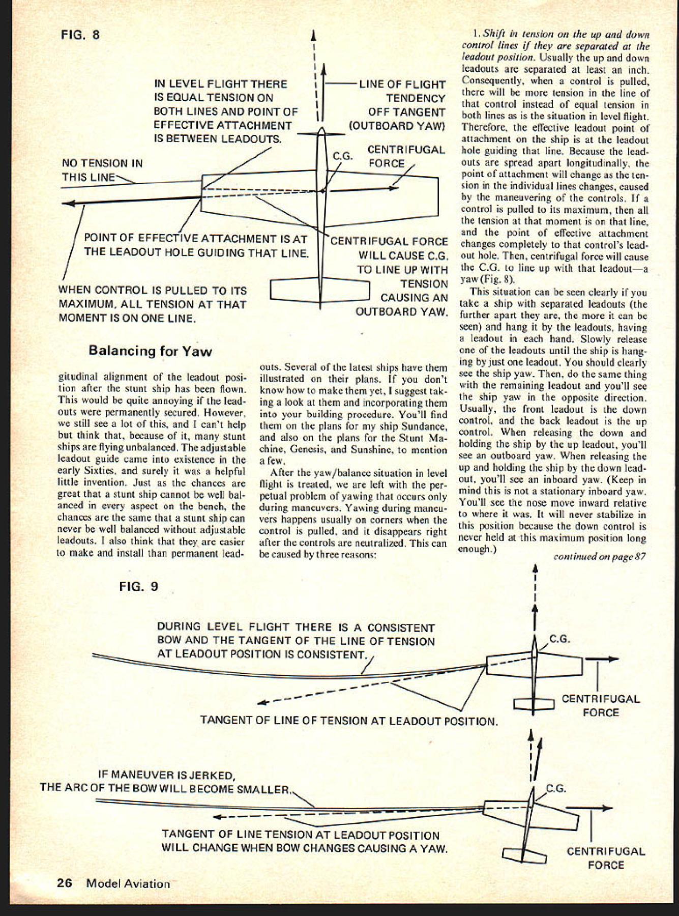

