
June 2005 39
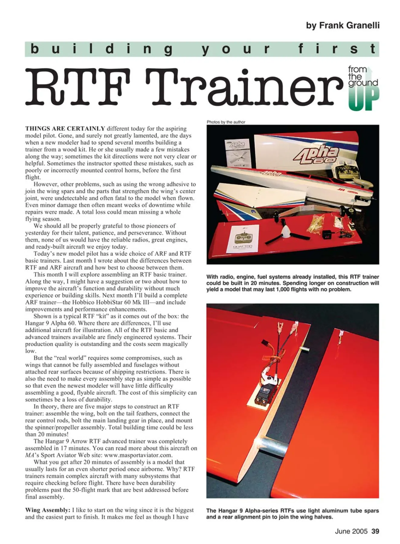
With radio, engine, fuel systems already installed, this RTF trainer
could be built in 20 minutes. Spending longer on construction will
yield a model that may last 1,000 flights with no problem.
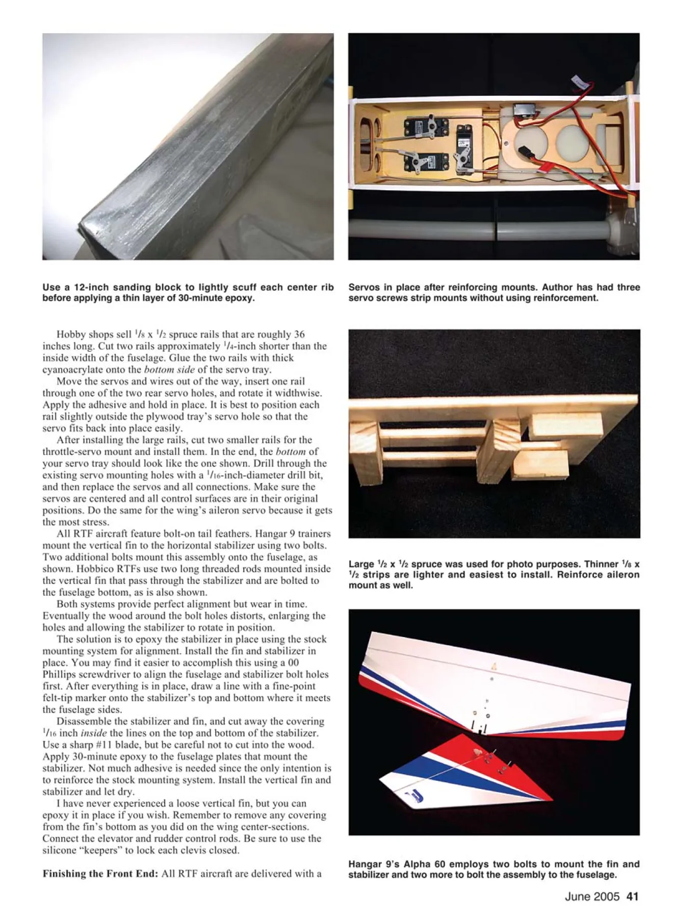
The Hangar 9 Alpha-series RTFs use light aluminum tube spars
and a rear alignment pin to join the wing halves.
RTF Trainer
b u i l d i n g y o u r f i r s t
by Frank Granelli
THINGS ARE CERTAINLY different today for the aspiring
model pilot. Gone, and surely not greatly lamented, are the days
when a new modeler had to spend several months building a
trainer from a wood kit. He or she usually made a few mistakes
along the way; sometimes the kit directions were not very clear or
helpful. Sometimes the instructor spotted these mistakes, such as
poorly or incorrectly mounted control horns, before the first
flight.
However, other problems, such as using the wrong adhesive to
join the wing spars and the parts that strengthen the wing’s center
joint, were undetectable and often fatal to the model when flown.
Even minor damage then often meant weeks of downtime while
repairs were made. A total loss could mean missing a whole
flying season.
We should all be properly grateful to those pioneers of
yesterday for their talent, patience, and perseverance. Without
them, none of us would have the reliable radios, great engines,
and ready-built aircraft we enjoy today.
Today’s new model pilot has a wide choice of ARF and RTF
basic trainers. Last month I wrote about the differences between
RTF and ARF aircraft and how best to choose between them.
This month I will explore assembling an RTF basic trainer.
Along the way, I might have a suggestion or two about how to
improve the aircraft’s function and durability without much
experience or building skills. Next month I’ll build a complete
ARF trainer—the Hobbico HobbiStar 60 Mk III—and include
improvements and performance enhancements.
Shown is a typical RTF “kit” as it comes out of the box: the
Hangar 9 Alpha 60. Where there are differences, I’ll use
additional aircraft for illustration. All of the RTF basic and
advanced trainers available are finely engineered systems. Their
production quality is outstanding and the costs seem magically
low.
But the “real world” requires some compromises, such as
wings that cannot be fully assembled and fuselages without
attached rear surfaces because of shipping restrictions. There is
also the need to make every assembly step as simple as possible
so that even the newest modeler will have little difficulty
assembling a good, flyable aircraft. The cost of this simplicity can
sometimes be a loss of durability.
In theory, there are five major steps to construct an RTF
trainer: assemble the wing, bolt on the tail feathers, connect the
rear control rods, bolt the main landing gear in place, and mount
the spinner/propeller assembly. Total building time could be less
than 20 minutes!
The Hangar 9 Arrow RTF advanced trainer was completely
assembled in 17 minutes. You can read more about this aircraft on
MA’s Sport Aviator Web site: www.masportaviator.com.
What you get after 20 minutes of assembly is a model that
usually lasts for an even shorter period once airborne. Why? RTF
trainers remain complex aircraft with many subsystems that
require checking before flight. There have been durability
problems past the 50-flight mark that are best addressed before
final assembly.
Wing Assembly: I like to start on the wing since it is the biggest
and the easiest part to finish. It makes me feel as though I have
Photos by the author
The Hobbico NexSTAR employs solid-steel rods to join wing
halves and a full-length plastic center rib for alignment.
Hobbico RTFs use screws to lock wing halves in place.
Hangar 9 RTFs use fuelproof clear tape. Screws and tape are
adequate methods, but adding epoxy is the most durable.
Raise covering away from center rib using sharp #11 blade to cut
away overlap that prevents a strong adhesive joint.
accomplished a whole lot in a short time. All RTF trainers use
metal spars to align the wing halves and to ensure a strong wing
center-section. There is usually a smaller rear metal pin to further
align the wing halves. If the wing has a plastic center rib, as the
Hobbico NexSTAR does, the rear pin is omitted.
Slide the metal spar into place and attach the second wing half.
Each center wing rib is coated to make it fuelproof. Sometimes
this coating flows into the spar and rear pin holes. Tolerances of
the spar-to-rib hole are tight to ensure a stiff wing. The smallest
amount of coating inside the hole can prevent the spar from
sliding in.
If that happens, use a fine, medium-size, round file—a rat-tail
file—to gently remove only the coating. Never enlarge the hole
itself.
Hobbico wing halves usually screw in place, as on the Avistar
40 advanced trainer. Hangar 9 wings are secured using clear tape.
Either method is good for approximately 200 flights; after that,
the constant flexing, sudden pullouts, and “difficult” landings take
their toll, and the wing spar begins to wear its wing rib mounting
holes, allowing the wing to get sloppy. Both methods allow
perfect wing alignment, so that is not a problem.
Use an extra-sharp hobby knife to remove only the covering
that overlaps the wing center-section. Lightly block-sand the wing
halves. Brush a thin film of 30-minute epoxy onto one wing’s
center rib. Assemble the wings as in the directions, hold them
together with masking tape, make sure the LEs and TEs are
aligned, and allow to dry.
This RTF wing will never loosen and will stay true throughout
the most strenuous maneuvers. Hold off on connecting the aileron
control rods for now.
Reinforcing the Fuselage: Notice how nice the servos look in
one of the photos, all in place and with everything connected. It is
good to have an installed fuel tank as well, and the engine is
comfortable nesting in its preinstalled mount. It seems a shame to
disturb all of that nice work, but I am going to do just that.
Experience has shown that some problems develop past the
100- to 200-flight mark that can be prevented at this point. You
may consider 200 flights too many to worry about, but it
represents only 10-20 weekends of five flights a day. That is less
than one season.
The servos are mounted on a thin plywood plate using small
screws, which sometimes loosen after many flights. It is a good
idea to center each servo’s control arm—the part to which the
control rod connects—and then remove the center screw and
control arm and the four servo-mounting screws. Remove the
servos, but leave them connected to the receiver.
June 2005 41
Use a 12-inch sanding block to lightly scuff each center rib
before applying a thin layer of 30-minute epoxy.
Large 1/2 x 1/2 spruce was used for photo purposes. Thinner 1/8 x
1/2 strips are lighter and easiest to install. Reinforce aileron
mount as well.
Hangar 9’s Alpha 60 employs two bolts to mount the fin and
stabilizer and two more to bolt the assembly to the fuselage.
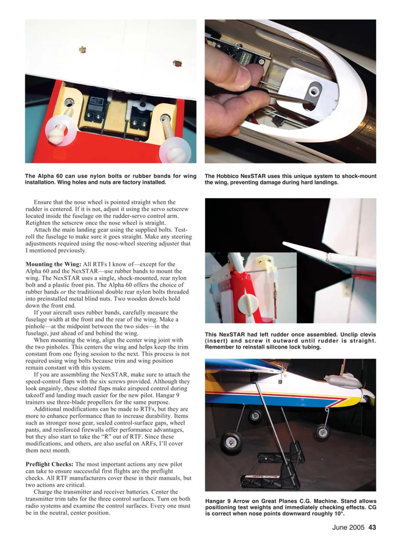
Servos in place after reinforcing mounts. Author has had three
servo screws strip mounts without using reinforcement.
Hobby shops sell 1/8 x 1/2 spruce rails that are roughly 36
inches long. Cut two rails approximately 1/4-inch shorter than the
inside width of the fuselage. Glue the two rails with thick
cyanoacrylate onto the bottom side of the servo tray.
Move the servos and wires out of the way, insert one rail
through one of the two rear servo holes, and rotate it widthwise.
Apply the adhesive and hold in place. It is best to position each
rail slightly outside the plywood tray’s servo hole so that the
servo fits back into place easily.
After installing the large rails, cut two smaller rails for the
throttle-servo mount and install them. In the end, the bottom of
your servo tray should look like the one shown. Drill through the
existing servo mounting holes with a 1/16-inch-diameter drill bit,
and then replace the servos and all connections. Make sure the
servos are centered and all control surfaces are in their original
positions. Do the same for the wing’s aileron servo because it gets
the most stress.
All RTF aircraft feature bolt-on tail feathers. Hangar 9 trainers
mount the vertical fin to the horizontal stabilizer using two bolts.
Two additional bolts mount this assembly onto the fuselage, as
shown. Hobbico RTFs use two long threaded rods mounted inside
the vertical fin that pass through the stabilizer and are bolted to
the fuselage bottom, as is also shown.
Both systems provide perfect alignment but wear in time.
Eventually the wood around the bolt holes distorts, enlarging the
holes and allowing the stabilizer to rotate in position.
The solution is to epoxy the stabilizer in place using the stock
mounting system for alignment. Install the fin and stabilizer in
place. You may find it easier to accomplish this using a 00
Phillips screwdriver to align the fuselage and stabilizer bolt holes
first. After everything is in place, draw a line with a fine-point
felt-tip marker onto the stabilizer’s top and bottom where it meets
the fuselage sides.
Disassemble the stabilizer and fin, and cut away the covering
1/16 inch inside the lines on the top and bottom of the stabilizer.
Use a sharp #11 blade, but be careful not to cut into the wood.
Apply 30-minute epoxy to the fuselage plates that mount the
stabilizer. Not much adhesive is needed since the only intention is
to reinforce the stock mounting system. Install the vertical fin and
stabilizer and let dry.
I have never experienced a loose vertical fin, but you can
epoxy it in place if you wish. Remember to remove any covering
from the fin’s bottom as you did on the wing center-sections.
Connect the elevator and rudder control rods. Be sure to use the
silicone “keepers” to lock each clevis closed.
Finishing the Front End: All RTF aircraft are delivered with a
Hobbico uses long threaded rods from fin, through stabilizer (left
out for clarity) that are bolted to fuselage bottom.
Using a sharp blade, gently cut 1/16 inch inside the lines but not
into the wood. Remove covering before gluing in place.
Apply removable thread-locking compound to muffler holes and
bolts. Do not use permanent type; that will prevent removal.
Remove excess plastic flashing from spinner cone to make sure
cone mounts firmly against spinner backplate on all sides.
loose, or uninstalled, propeller and spinner for safety purposes.
Bolts might loosen during climate changes that occur during
shipping, and that can be a safety hazard. If the propeller is
uninstalled, leave it off for now. If it is installed, remove it by
reversing the installation instructions.
Remove the muffler. This is necessary because none of the
RTFs use thread-locking compound, so the mufflers loosen in
the first few flights.
While the muffler is off, tighten whatever bolts hold the
engine and engine mount in place. Do not remove the engine
itself, especially if a clamp mount is used. Realigning the thrust
angle can be difficult in such a mount. Just make sure the bolts
are tight.
Also while the muffler is off, check the throttle movement.
With the throttle stick at high, positioned away from you, and
with the throttle trim on high, the throttle barrel should be just
fully open. If not, adjust the clevis by turning it until the barrel
is fully opened.
Leave the trim on high and lower the throttle stick all the
way. The barrel should close until there is roughly a 1/16-inch
opening. Lower the throttle trim lever all the way, and the barrel
should just close completely. This small preflight check is easier
to perform now because clevis adjustment is easiest without the
muffler.
Apply the removable type of thread-locking compound to the
muffler holes and the mounting bolts. Coating just one side is
seldom enough. With both covered, your muffler will be yours
to keep forever. This beats combing the fields looking for it after
every 20 flights. Install the muffler.
Install the propeller using the correct-size box wrench.
Today’s powerful engines can start backward, putting extra
stress on the prop nut’s firmness. The small four-way tool that
was popular years ago may not provide sufficient torque.
All RTF spinners use small screws to mount the spinner cone
to the backplate. Make sure the spinner cone rests fully into the
backplate’s groove before tightening these screws. The screws
themselves are not powerful enough to “pull” the spinner cone
into place if there is a misalignment. Tighten the screws firmly,
but do not apply excessive force; they are just going into fragile
plastic threads. Use a small hobby screwdriver for this task.
It may be necessary to remove excess flashing from the
spinner cutouts surrounding the propeller. Use a sharp #11 blade
in a hobby knife to remove minute pieces one at a time. Recheck
after each cut.
If there is more than a 1/64-inch difference, preventing the
spinner’s mounting properly, chances are that the propeller is in
the incorrect position on the backplate. Check this before cutting
the spinners.
June 2005 43
The Hobbico NexSTAR uses this unique system to shock-mount
the wing, preventing damage during hard landings.
The Alpha 60 can use nylon bolts or rubber bands for wing
installation. Wing holes and nuts are factory installed.
This NexSTAR had left rudder once assembled. Unclip clevis
(insert) and screw it outward until rudder is straight.
Remember to reinstall silicone lock tubing.
Hangar 9 Arrow on Great Planes C.G. Machine. Stand allows
positioning test weights and immediately checking effects. CG
is correct when nose points downward roughly 10°.
Ensure that the nose wheel is pointed straight when the
rudder is centered. If it is not, adjust it using the servo setscrew
located inside the fuselage on the rudder-servo control arm.
Retighten the setscrew once the nose wheel is straight.
Attach the main landing gear using the supplied bolts. Testroll
the fuselage to make sure it goes straight. Make any steering
adjustments required using the nose-wheel steering adjuster that
I mentioned previously.
Mounting the Wing: All RTFs I know of—except for the
Alpha 60 and the NexSTAR—use rubber bands to mount the
wing. The NexSTAR uses a single, shock-mounted, rear nylon
bolt and a plastic front pin. The Alpha 60 offers the choice of
rubber bands or the traditional double rear nylon bolts threaded
into preinstalled metal blind nuts. Two wooden dowels hold
down the front end.
If your aircraft uses rubber bands, carefully measure the
fuselage width at the front and the rear of the wing. Make a
pinhole—at the midpoint between the two sides—in the
fuselage, just ahead of and behind the wing.
When mounting the wing, align the center wing joint with
the two pinholes. This centers the wing and helps keep the trim
constant from one flying session to the next. This process is not
required using wing bolts because trim and wing position
remain constant with this system.
If you are assembling the NexSTAR, make sure to attach the
speed-control flaps with the six screws provided. Although they
look ungainly, these slotted flaps make airspeed control during
takeoff and landing much easier for the new pilot. Hangar 9
trainers use three-blade propellers for the same purpose.
Additional modifications can be made to RTFs, but they are
more to enhance performance than to increase durability. Items
such as stronger nose gear, sealed control-surface gaps, wheel
pants, and reinforced firewalls offer performance advantages,
but they also start to take the “R” out of RTF. Since these
modifications, and others, are also useful on ARFs, I’ll cover
them next month.
Preflight Checks: The most important actions any new pilot
can take to ensure successful first flights are the preflight
checks. All RTF manufacturers cover these in their manuals, but
two actions are critical.
Charge the transmitter and receiver batteries. Center the
transmitter trim tabs for the three control surfaces. Turn on both
radio systems and examine the control surfaces. Every one must
be in the neutral, center position.
If a surface is not centered, such as left
rudder or down-elevator, leave the radio
system turned on and adjust the clevis that
connects to the control horn until that
surface is in the neutral, center position.
No aircraft will fly straight unless all
control surfaces, especially the rudder, are
centered. It is easiest to learn on an
airplane that flies straight and goes where
it is pointed. RTFs are so well designed
that it is nearly impossible to misalign the
wing halves during assembly. Therefore, if
a great deal of aileron trim is required to
fly straight, it usually means the rudder is
off-center.
The last crucial step is to check the
aircraft’s longitudinal CG. Does the
completely assembled airplane balance
front to back exactly at the point that the
instructions require?
Most RTFs do balance perfectly. If
yours does not, a few stick-on lead
weights, available at the hobby shop,
might be required. A photo shows the
Arrow having its CG checked using the
Great Planes stand that is designed for this
purpose. Never fly a new model without
checking and adjusting its CG.
The last check is to make sure all
screws, such as the servo control-arm
screw, the nose-wheel steering-arm
locking screw, and any other fasteners not
checked during assembly, are firmly
tightened.
Next month I will build and modify the
HobbiStar 60 Mk III ARF trainer. If you
want more extensive photo details about
checking an RTF trainer than it is possible
to cover here, read “Ready to Fly? Well …
Maybe” on Sport Aviator at
www.masportaviator.com/ah.asp/CatID=2
&ID=23. MA
Frank Granelli
24 Old Middletown Rd.
Rockaway NJ 07866
Edition: Model Aviation - 2005/06
Page Numbers: 39,40,41,42,43,44

Edition: Model Aviation - 2005/06
Page Numbers: 39,40,41,42,43,44
June 2005 39
With radio, engine, fuel systems already installed, this RTF trainer
could be built in 20 minutes. Spending longer on construction will
yield a model that may last 1,000 flights with no problem.
The Hangar 9 Alpha-series RTFs use light aluminum tube spars
and a rear alignment pin to join the wing halves.
RTF Trainer
b u i l d i n g y o u r f i r s t
by Frank Granelli
THINGS ARE CERTAINLY different today for the aspiring
model pilot. Gone, and surely not greatly lamented, are the days
when a new modeler had to spend several months building a
trainer from a wood kit. He or she usually made a few mistakes
along the way; sometimes the kit directions were not very clear or
helpful. Sometimes the instructor spotted these mistakes, such as
poorly or incorrectly mounted control horns, before the first
flight.
However, other problems, such as using the wrong adhesive to
join the wing spars and the parts that strengthen the wing’s center
joint, were undetectable and often fatal to the model when flown.
Even minor damage then often meant weeks of downtime while
repairs were made. A total loss could mean missing a whole
flying season.
We should all be properly grateful to those pioneers of
yesterday for their talent, patience, and perseverance. Without
them, none of us would have the reliable radios, great engines,
and ready-built aircraft we enjoy today.
Today’s new model pilot has a wide choice of ARF and RTF
basic trainers. Last month I wrote about the differences between
RTF and ARF aircraft and how best to choose between them.
This month I will explore assembling an RTF basic trainer.
Along the way, I might have a suggestion or two about how to
improve the aircraft’s function and durability without much
experience or building skills. Next month I’ll build a complete
ARF trainer—the Hobbico HobbiStar 60 Mk III—and include
improvements and performance enhancements.
Shown is a typical RTF “kit” as it comes out of the box: the
Hangar 9 Alpha 60. Where there are differences, I’ll use
additional aircraft for illustration. All of the RTF basic and
advanced trainers available are finely engineered systems. Their
production quality is outstanding and the costs seem magically
low.
But the “real world” requires some compromises, such as
wings that cannot be fully assembled and fuselages without
attached rear surfaces because of shipping restrictions. There is
also the need to make every assembly step as simple as possible
so that even the newest modeler will have little difficulty
assembling a good, flyable aircraft. The cost of this simplicity can
sometimes be a loss of durability.
In theory, there are five major steps to construct an RTF
trainer: assemble the wing, bolt on the tail feathers, connect the
rear control rods, bolt the main landing gear in place, and mount
the spinner/propeller assembly. Total building time could be less
than 20 minutes!
The Hangar 9 Arrow RTF advanced trainer was completely
assembled in 17 minutes. You can read more about this aircraft on
MA’s Sport Aviator Web site: www.masportaviator.com.
What you get after 20 minutes of assembly is a model that
usually lasts for an even shorter period once airborne. Why? RTF
trainers remain complex aircraft with many subsystems that
require checking before flight. There have been durability
problems past the 50-flight mark that are best addressed before
final assembly.
Wing Assembly: I like to start on the wing since it is the biggest
and the easiest part to finish. It makes me feel as though I have
Photos by the author
The Hobbico NexSTAR employs solid-steel rods to join wing
halves and a full-length plastic center rib for alignment.
Hobbico RTFs use screws to lock wing halves in place.
Hangar 9 RTFs use fuelproof clear tape. Screws and tape are
adequate methods, but adding epoxy is the most durable.
Raise covering away from center rib using sharp #11 blade to cut
away overlap that prevents a strong adhesive joint.
accomplished a whole lot in a short time. All RTF trainers use
metal spars to align the wing halves and to ensure a strong wing
center-section. There is usually a smaller rear metal pin to further
align the wing halves. If the wing has a plastic center rib, as the
Hobbico NexSTAR does, the rear pin is omitted.
Slide the metal spar into place and attach the second wing half.
Each center wing rib is coated to make it fuelproof. Sometimes
this coating flows into the spar and rear pin holes. Tolerances of
the spar-to-rib hole are tight to ensure a stiff wing. The smallest
amount of coating inside the hole can prevent the spar from
sliding in.
If that happens, use a fine, medium-size, round file—a rat-tail
file—to gently remove only the coating. Never enlarge the hole
itself.
Hobbico wing halves usually screw in place, as on the Avistar
40 advanced trainer. Hangar 9 wings are secured using clear tape.
Either method is good for approximately 200 flights; after that,
the constant flexing, sudden pullouts, and “difficult” landings take
their toll, and the wing spar begins to wear its wing rib mounting
holes, allowing the wing to get sloppy. Both methods allow
perfect wing alignment, so that is not a problem.
Use an extra-sharp hobby knife to remove only the covering
that overlaps the wing center-section. Lightly block-sand the wing
halves. Brush a thin film of 30-minute epoxy onto one wing’s
center rib. Assemble the wings as in the directions, hold them
together with masking tape, make sure the LEs and TEs are
aligned, and allow to dry.
This RTF wing will never loosen and will stay true throughout
the most strenuous maneuvers. Hold off on connecting the aileron
control rods for now.
Reinforcing the Fuselage: Notice how nice the servos look in
one of the photos, all in place and with everything connected. It is
good to have an installed fuel tank as well, and the engine is
comfortable nesting in its preinstalled mount. It seems a shame to
disturb all of that nice work, but I am going to do just that.
Experience has shown that some problems develop past the
100- to 200-flight mark that can be prevented at this point. You
may consider 200 flights too many to worry about, but it
represents only 10-20 weekends of five flights a day. That is less
than one season.
The servos are mounted on a thin plywood plate using small
screws, which sometimes loosen after many flights. It is a good
idea to center each servo’s control arm—the part to which the
control rod connects—and then remove the center screw and
control arm and the four servo-mounting screws. Remove the
servos, but leave them connected to the receiver.
June 2005 41
Use a 12-inch sanding block to lightly scuff each center rib
before applying a thin layer of 30-minute epoxy.
Large 1/2 x 1/2 spruce was used for photo purposes. Thinner 1/8 x
1/2 strips are lighter and easiest to install. Reinforce aileron
mount as well.
Hangar 9’s Alpha 60 employs two bolts to mount the fin and
stabilizer and two more to bolt the assembly to the fuselage.
Servos in place after reinforcing mounts. Author has had three
servo screws strip mounts without using reinforcement.
Hobby shops sell 1/8 x 1/2 spruce rails that are roughly 36
inches long. Cut two rails approximately 1/4-inch shorter than the
inside width of the fuselage. Glue the two rails with thick
cyanoacrylate onto the bottom side of the servo tray.
Move the servos and wires out of the way, insert one rail
through one of the two rear servo holes, and rotate it widthwise.
Apply the adhesive and hold in place. It is best to position each
rail slightly outside the plywood tray’s servo hole so that the
servo fits back into place easily.
After installing the large rails, cut two smaller rails for the
throttle-servo mount and install them. In the end, the bottom of
your servo tray should look like the one shown. Drill through the
existing servo mounting holes with a 1/16-inch-diameter drill bit,
and then replace the servos and all connections. Make sure the
servos are centered and all control surfaces are in their original
positions. Do the same for the wing’s aileron servo because it gets
the most stress.
All RTF aircraft feature bolt-on tail feathers. Hangar 9 trainers
mount the vertical fin to the horizontal stabilizer using two bolts.
Two additional bolts mount this assembly onto the fuselage, as
shown. Hobbico RTFs use two long threaded rods mounted inside
the vertical fin that pass through the stabilizer and are bolted to
the fuselage bottom, as is also shown.
Both systems provide perfect alignment but wear in time.
Eventually the wood around the bolt holes distorts, enlarging the
holes and allowing the stabilizer to rotate in position.
The solution is to epoxy the stabilizer in place using the stock
mounting system for alignment. Install the fin and stabilizer in
place. You may find it easier to accomplish this using a 00
Phillips screwdriver to align the fuselage and stabilizer bolt holes
first. After everything is in place, draw a line with a fine-point
felt-tip marker onto the stabilizer’s top and bottom where it meets
the fuselage sides.
Disassemble the stabilizer and fin, and cut away the covering
1/16 inch inside the lines on the top and bottom of the stabilizer.
Use a sharp #11 blade, but be careful not to cut into the wood.
Apply 30-minute epoxy to the fuselage plates that mount the
stabilizer. Not much adhesive is needed since the only intention is
to reinforce the stock mounting system. Install the vertical fin and
stabilizer and let dry.
I have never experienced a loose vertical fin, but you can
epoxy it in place if you wish. Remember to remove any covering
from the fin’s bottom as you did on the wing center-sections.
Connect the elevator and rudder control rods. Be sure to use the
silicone “keepers” to lock each clevis closed.
Finishing the Front End: All RTF aircraft are delivered with a
Hobbico uses long threaded rods from fin, through stabilizer (left
out for clarity) that are bolted to fuselage bottom.
Using a sharp blade, gently cut 1/16 inch inside the lines but not
into the wood. Remove covering before gluing in place.
Apply removable thread-locking compound to muffler holes and
bolts. Do not use permanent type; that will prevent removal.
Remove excess plastic flashing from spinner cone to make sure
cone mounts firmly against spinner backplate on all sides.
loose, or uninstalled, propeller and spinner for safety purposes.
Bolts might loosen during climate changes that occur during
shipping, and that can be a safety hazard. If the propeller is
uninstalled, leave it off for now. If it is installed, remove it by
reversing the installation instructions.
Remove the muffler. This is necessary because none of the
RTFs use thread-locking compound, so the mufflers loosen in
the first few flights.
While the muffler is off, tighten whatever bolts hold the
engine and engine mount in place. Do not remove the engine
itself, especially if a clamp mount is used. Realigning the thrust
angle can be difficult in such a mount. Just make sure the bolts
are tight.
Also while the muffler is off, check the throttle movement.
With the throttle stick at high, positioned away from you, and
with the throttle trim on high, the throttle barrel should be just
fully open. If not, adjust the clevis by turning it until the barrel
is fully opened.
Leave the trim on high and lower the throttle stick all the
way. The barrel should close until there is roughly a 1/16-inch
opening. Lower the throttle trim lever all the way, and the barrel
should just close completely. This small preflight check is easier
to perform now because clevis adjustment is easiest without the
muffler.
Apply the removable type of thread-locking compound to the
muffler holes and the mounting bolts. Coating just one side is
seldom enough. With both covered, your muffler will be yours
to keep forever. This beats combing the fields looking for it after
every 20 flights. Install the muffler.
Install the propeller using the correct-size box wrench.
Today’s powerful engines can start backward, putting extra
stress on the prop nut’s firmness. The small four-way tool that
was popular years ago may not provide sufficient torque.
All RTF spinners use small screws to mount the spinner cone
to the backplate. Make sure the spinner cone rests fully into the
backplate’s groove before tightening these screws. The screws
themselves are not powerful enough to “pull” the spinner cone
into place if there is a misalignment. Tighten the screws firmly,
but do not apply excessive force; they are just going into fragile
plastic threads. Use a small hobby screwdriver for this task.
It may be necessary to remove excess flashing from the
spinner cutouts surrounding the propeller. Use a sharp #11 blade
in a hobby knife to remove minute pieces one at a time. Recheck
after each cut.
If there is more than a 1/64-inch difference, preventing the
spinner’s mounting properly, chances are that the propeller is in
the incorrect position on the backplate. Check this before cutting
the spinners.
June 2005 43
The Hobbico NexSTAR uses this unique system to shock-mount
the wing, preventing damage during hard landings.
The Alpha 60 can use nylon bolts or rubber bands for wing
installation. Wing holes and nuts are factory installed.
This NexSTAR had left rudder once assembled. Unclip clevis
(insert) and screw it outward until rudder is straight.
Remember to reinstall silicone lock tubing.
Hangar 9 Arrow on Great Planes C.G. Machine. Stand allows
positioning test weights and immediately checking effects. CG
is correct when nose points downward roughly 10°.
Ensure that the nose wheel is pointed straight when the
rudder is centered. If it is not, adjust it using the servo setscrew
located inside the fuselage on the rudder-servo control arm.
Retighten the setscrew once the nose wheel is straight.
Attach the main landing gear using the supplied bolts. Testroll
the fuselage to make sure it goes straight. Make any steering
adjustments required using the nose-wheel steering adjuster that
I mentioned previously.
Mounting the Wing: All RTFs I know of—except for the
Alpha 60 and the NexSTAR—use rubber bands to mount the
wing. The NexSTAR uses a single, shock-mounted, rear nylon
bolt and a plastic front pin. The Alpha 60 offers the choice of
rubber bands or the traditional double rear nylon bolts threaded
into preinstalled metal blind nuts. Two wooden dowels hold
down the front end.
If your aircraft uses rubber bands, carefully measure the
fuselage width at the front and the rear of the wing. Make a
pinhole—at the midpoint between the two sides—in the
fuselage, just ahead of and behind the wing.
When mounting the wing, align the center wing joint with
the two pinholes. This centers the wing and helps keep the trim
constant from one flying session to the next. This process is not
required using wing bolts because trim and wing position
remain constant with this system.
If you are assembling the NexSTAR, make sure to attach the
speed-control flaps with the six screws provided. Although they
look ungainly, these slotted flaps make airspeed control during
takeoff and landing much easier for the new pilot. Hangar 9
trainers use three-blade propellers for the same purpose.
Additional modifications can be made to RTFs, but they are
more to enhance performance than to increase durability. Items
such as stronger nose gear, sealed control-surface gaps, wheel
pants, and reinforced firewalls offer performance advantages,
but they also start to take the “R” out of RTF. Since these
modifications, and others, are also useful on ARFs, I’ll cover
them next month.
Preflight Checks: The most important actions any new pilot
can take to ensure successful first flights are the preflight
checks. All RTF manufacturers cover these in their manuals, but
two actions are critical.
Charge the transmitter and receiver batteries. Center the
transmitter trim tabs for the three control surfaces. Turn on both
radio systems and examine the control surfaces. Every one must
be in the neutral, center position.
If a surface is not centered, such as left
rudder or down-elevator, leave the radio
system turned on and adjust the clevis that
connects to the control horn until that
surface is in the neutral, center position.
No aircraft will fly straight unless all
control surfaces, especially the rudder, are
centered. It is easiest to learn on an
airplane that flies straight and goes where
it is pointed. RTFs are so well designed
that it is nearly impossible to misalign the
wing halves during assembly. Therefore, if
a great deal of aileron trim is required to
fly straight, it usually means the rudder is
off-center.
The last crucial step is to check the
aircraft’s longitudinal CG. Does the
completely assembled airplane balance
front to back exactly at the point that the
instructions require?
Most RTFs do balance perfectly. If
yours does not, a few stick-on lead
weights, available at the hobby shop,
might be required. A photo shows the
Arrow having its CG checked using the
Great Planes stand that is designed for this
purpose. Never fly a new model without
checking and adjusting its CG.
The last check is to make sure all
screws, such as the servo control-arm
screw, the nose-wheel steering-arm
locking screw, and any other fasteners not
checked during assembly, are firmly
tightened.
Next month I will build and modify the
HobbiStar 60 Mk III ARF trainer. If you
want more extensive photo details about
checking an RTF trainer than it is possible
to cover here, read “Ready to Fly? Well …
Maybe” on Sport Aviator at
www.masportaviator.com/ah.asp/CatID=2
&ID=23. MA
Frank Granelli
24 Old Middletown Rd.
Rockaway NJ 07866
Edition: Model Aviation - 2005/06
Page Numbers: 39,40,41,42,43,44
June 2005 39
With radio, engine, fuel systems already installed, this RTF trainer
could be built in 20 minutes. Spending longer on construction will
yield a model that may last 1,000 flights with no problem.
The Hangar 9 Alpha-series RTFs use light aluminum tube spars
and a rear alignment pin to join the wing halves.
RTF Trainer
b u i l d i n g y o u r f i r s t
by Frank Granelli
THINGS ARE CERTAINLY different today for the aspiring
model pilot. Gone, and surely not greatly lamented, are the days
when a new modeler had to spend several months building a
trainer from a wood kit. He or she usually made a few mistakes
along the way; sometimes the kit directions were not very clear or
helpful. Sometimes the instructor spotted these mistakes, such as
poorly or incorrectly mounted control horns, before the first
flight.
However, other problems, such as using the wrong adhesive to
join the wing spars and the parts that strengthen the wing’s center
joint, were undetectable and often fatal to the model when flown.
Even minor damage then often meant weeks of downtime while
repairs were made. A total loss could mean missing a whole
flying season.
We should all be properly grateful to those pioneers of
yesterday for their talent, patience, and perseverance. Without
them, none of us would have the reliable radios, great engines,
and ready-built aircraft we enjoy today.
Today’s new model pilot has a wide choice of ARF and RTF
basic trainers. Last month I wrote about the differences between
RTF and ARF aircraft and how best to choose between them.
This month I will explore assembling an RTF basic trainer.
Along the way, I might have a suggestion or two about how to
improve the aircraft’s function and durability without much
experience or building skills. Next month I’ll build a complete
ARF trainer—the Hobbico HobbiStar 60 Mk III—and include
improvements and performance enhancements.
Shown is a typical RTF “kit” as it comes out of the box: the
Hangar 9 Alpha 60. Where there are differences, I’ll use
additional aircraft for illustration. All of the RTF basic and
advanced trainers available are finely engineered systems. Their
production quality is outstanding and the costs seem magically
low.
But the “real world” requires some compromises, such as
wings that cannot be fully assembled and fuselages without
attached rear surfaces because of shipping restrictions. There is
also the need to make every assembly step as simple as possible
so that even the newest modeler will have little difficulty
assembling a good, flyable aircraft. The cost of this simplicity can
sometimes be a loss of durability.
In theory, there are five major steps to construct an RTF
trainer: assemble the wing, bolt on the tail feathers, connect the
rear control rods, bolt the main landing gear in place, and mount
the spinner/propeller assembly. Total building time could be less
than 20 minutes!
The Hangar 9 Arrow RTF advanced trainer was completely
assembled in 17 minutes. You can read more about this aircraft on
MA’s Sport Aviator Web site: www.masportaviator.com.
What you get after 20 minutes of assembly is a model that
usually lasts for an even shorter period once airborne. Why? RTF
trainers remain complex aircraft with many subsystems that
require checking before flight. There have been durability
problems past the 50-flight mark that are best addressed before
final assembly.
Wing Assembly: I like to start on the wing since it is the biggest
and the easiest part to finish. It makes me feel as though I have
Photos by the author
The Hobbico NexSTAR employs solid-steel rods to join wing
halves and a full-length plastic center rib for alignment.
Hobbico RTFs use screws to lock wing halves in place.
Hangar 9 RTFs use fuelproof clear tape. Screws and tape are
adequate methods, but adding epoxy is the most durable.
Raise covering away from center rib using sharp #11 blade to cut
away overlap that prevents a strong adhesive joint.
accomplished a whole lot in a short time. All RTF trainers use
metal spars to align the wing halves and to ensure a strong wing
center-section. There is usually a smaller rear metal pin to further
align the wing halves. If the wing has a plastic center rib, as the
Hobbico NexSTAR does, the rear pin is omitted.
Slide the metal spar into place and attach the second wing half.
Each center wing rib is coated to make it fuelproof. Sometimes
this coating flows into the spar and rear pin holes. Tolerances of
the spar-to-rib hole are tight to ensure a stiff wing. The smallest
amount of coating inside the hole can prevent the spar from
sliding in.
If that happens, use a fine, medium-size, round file—a rat-tail
file—to gently remove only the coating. Never enlarge the hole
itself.
Hobbico wing halves usually screw in place, as on the Avistar
40 advanced trainer. Hangar 9 wings are secured using clear tape.
Either method is good for approximately 200 flights; after that,
the constant flexing, sudden pullouts, and “difficult” landings take
their toll, and the wing spar begins to wear its wing rib mounting
holes, allowing the wing to get sloppy. Both methods allow
perfect wing alignment, so that is not a problem.
Use an extra-sharp hobby knife to remove only the covering
that overlaps the wing center-section. Lightly block-sand the wing
halves. Brush a thin film of 30-minute epoxy onto one wing’s
center rib. Assemble the wings as in the directions, hold them
together with masking tape, make sure the LEs and TEs are
aligned, and allow to dry.
This RTF wing will never loosen and will stay true throughout
the most strenuous maneuvers. Hold off on connecting the aileron
control rods for now.
Reinforcing the Fuselage: Notice how nice the servos look in
one of the photos, all in place and with everything connected. It is
good to have an installed fuel tank as well, and the engine is
comfortable nesting in its preinstalled mount. It seems a shame to
disturb all of that nice work, but I am going to do just that.
Experience has shown that some problems develop past the
100- to 200-flight mark that can be prevented at this point. You
may consider 200 flights too many to worry about, but it
represents only 10-20 weekends of five flights a day. That is less
than one season.
The servos are mounted on a thin plywood plate using small
screws, which sometimes loosen after many flights. It is a good
idea to center each servo’s control arm—the part to which the
control rod connects—and then remove the center screw and
control arm and the four servo-mounting screws. Remove the
servos, but leave them connected to the receiver.
June 2005 41
Use a 12-inch sanding block to lightly scuff each center rib
before applying a thin layer of 30-minute epoxy.
Large 1/2 x 1/2 spruce was used for photo purposes. Thinner 1/8 x
1/2 strips are lighter and easiest to install. Reinforce aileron
mount as well.
Hangar 9’s Alpha 60 employs two bolts to mount the fin and
stabilizer and two more to bolt the assembly to the fuselage.
Servos in place after reinforcing mounts. Author has had three
servo screws strip mounts without using reinforcement.
Hobby shops sell 1/8 x 1/2 spruce rails that are roughly 36
inches long. Cut two rails approximately 1/4-inch shorter than the
inside width of the fuselage. Glue the two rails with thick
cyanoacrylate onto the bottom side of the servo tray.
Move the servos and wires out of the way, insert one rail
through one of the two rear servo holes, and rotate it widthwise.
Apply the adhesive and hold in place. It is best to position each
rail slightly outside the plywood tray’s servo hole so that the
servo fits back into place easily.
After installing the large rails, cut two smaller rails for the
throttle-servo mount and install them. In the end, the bottom of
your servo tray should look like the one shown. Drill through the
existing servo mounting holes with a 1/16-inch-diameter drill bit,
and then replace the servos and all connections. Make sure the
servos are centered and all control surfaces are in their original
positions. Do the same for the wing’s aileron servo because it gets
the most stress.
All RTF aircraft feature bolt-on tail feathers. Hangar 9 trainers
mount the vertical fin to the horizontal stabilizer using two bolts.
Two additional bolts mount this assembly onto the fuselage, as
shown. Hobbico RTFs use two long threaded rods mounted inside
the vertical fin that pass through the stabilizer and are bolted to
the fuselage bottom, as is also shown.
Both systems provide perfect alignment but wear in time.
Eventually the wood around the bolt holes distorts, enlarging the
holes and allowing the stabilizer to rotate in position.
The solution is to epoxy the stabilizer in place using the stock
mounting system for alignment. Install the fin and stabilizer in
place. You may find it easier to accomplish this using a 00
Phillips screwdriver to align the fuselage and stabilizer bolt holes
first. After everything is in place, draw a line with a fine-point
felt-tip marker onto the stabilizer’s top and bottom where it meets
the fuselage sides.
Disassemble the stabilizer and fin, and cut away the covering
1/16 inch inside the lines on the top and bottom of the stabilizer.
Use a sharp #11 blade, but be careful not to cut into the wood.
Apply 30-minute epoxy to the fuselage plates that mount the
stabilizer. Not much adhesive is needed since the only intention is
to reinforce the stock mounting system. Install the vertical fin and
stabilizer and let dry.
I have never experienced a loose vertical fin, but you can
epoxy it in place if you wish. Remember to remove any covering
from the fin’s bottom as you did on the wing center-sections.
Connect the elevator and rudder control rods. Be sure to use the
silicone “keepers” to lock each clevis closed.
Finishing the Front End: All RTF aircraft are delivered with a
Hobbico uses long threaded rods from fin, through stabilizer (left
out for clarity) that are bolted to fuselage bottom.
Using a sharp blade, gently cut 1/16 inch inside the lines but not
into the wood. Remove covering before gluing in place.
Apply removable thread-locking compound to muffler holes and
bolts. Do not use permanent type; that will prevent removal.
Remove excess plastic flashing from spinner cone to make sure
cone mounts firmly against spinner backplate on all sides.
loose, or uninstalled, propeller and spinner for safety purposes.
Bolts might loosen during climate changes that occur during
shipping, and that can be a safety hazard. If the propeller is
uninstalled, leave it off for now. If it is installed, remove it by
reversing the installation instructions.
Remove the muffler. This is necessary because none of the
RTFs use thread-locking compound, so the mufflers loosen in
the first few flights.
While the muffler is off, tighten whatever bolts hold the
engine and engine mount in place. Do not remove the engine
itself, especially if a clamp mount is used. Realigning the thrust
angle can be difficult in such a mount. Just make sure the bolts
are tight.
Also while the muffler is off, check the throttle movement.
With the throttle stick at high, positioned away from you, and
with the throttle trim on high, the throttle barrel should be just
fully open. If not, adjust the clevis by turning it until the barrel
is fully opened.
Leave the trim on high and lower the throttle stick all the
way. The barrel should close until there is roughly a 1/16-inch
opening. Lower the throttle trim lever all the way, and the barrel
should just close completely. This small preflight check is easier
to perform now because clevis adjustment is easiest without the
muffler.
Apply the removable type of thread-locking compound to the
muffler holes and the mounting bolts. Coating just one side is
seldom enough. With both covered, your muffler will be yours
to keep forever. This beats combing the fields looking for it after
every 20 flights. Install the muffler.
Install the propeller using the correct-size box wrench.
Today’s powerful engines can start backward, putting extra
stress on the prop nut’s firmness. The small four-way tool that
was popular years ago may not provide sufficient torque.
All RTF spinners use small screws to mount the spinner cone
to the backplate. Make sure the spinner cone rests fully into the
backplate’s groove before tightening these screws. The screws
themselves are not powerful enough to “pull” the spinner cone
into place if there is a misalignment. Tighten the screws firmly,
but do not apply excessive force; they are just going into fragile
plastic threads. Use a small hobby screwdriver for this task.
It may be necessary to remove excess flashing from the
spinner cutouts surrounding the propeller. Use a sharp #11 blade
in a hobby knife to remove minute pieces one at a time. Recheck
after each cut.
If there is more than a 1/64-inch difference, preventing the
spinner’s mounting properly, chances are that the propeller is in
the incorrect position on the backplate. Check this before cutting
the spinners.
June 2005 43
The Hobbico NexSTAR uses this unique system to shock-mount
the wing, preventing damage during hard landings.
The Alpha 60 can use nylon bolts or rubber bands for wing
installation. Wing holes and nuts are factory installed.
This NexSTAR had left rudder once assembled. Unclip clevis
(insert) and screw it outward until rudder is straight.
Remember to reinstall silicone lock tubing.
Hangar 9 Arrow on Great Planes C.G. Machine. Stand allows
positioning test weights and immediately checking effects. CG
is correct when nose points downward roughly 10°.
Ensure that the nose wheel is pointed straight when the
rudder is centered. If it is not, adjust it using the servo setscrew
located inside the fuselage on the rudder-servo control arm.
Retighten the setscrew once the nose wheel is straight.
Attach the main landing gear using the supplied bolts. Testroll
the fuselage to make sure it goes straight. Make any steering
adjustments required using the nose-wheel steering adjuster that
I mentioned previously.
Mounting the Wing: All RTFs I know of—except for the
Alpha 60 and the NexSTAR—use rubber bands to mount the
wing. The NexSTAR uses a single, shock-mounted, rear nylon
bolt and a plastic front pin. The Alpha 60 offers the choice of
rubber bands or the traditional double rear nylon bolts threaded
into preinstalled metal blind nuts. Two wooden dowels hold
down the front end.
If your aircraft uses rubber bands, carefully measure the
fuselage width at the front and the rear of the wing. Make a
pinhole—at the midpoint between the two sides—in the
fuselage, just ahead of and behind the wing.
When mounting the wing, align the center wing joint with
the two pinholes. This centers the wing and helps keep the trim
constant from one flying session to the next. This process is not
required using wing bolts because trim and wing position
remain constant with this system.
If you are assembling the NexSTAR, make sure to attach the
speed-control flaps with the six screws provided. Although they
look ungainly, these slotted flaps make airspeed control during
takeoff and landing much easier for the new pilot. Hangar 9
trainers use three-blade propellers for the same purpose.
Additional modifications can be made to RTFs, but they are
more to enhance performance than to increase durability. Items
such as stronger nose gear, sealed control-surface gaps, wheel
pants, and reinforced firewalls offer performance advantages,
but they also start to take the “R” out of RTF. Since these
modifications, and others, are also useful on ARFs, I’ll cover
them next month.
Preflight Checks: The most important actions any new pilot
can take to ensure successful first flights are the preflight
checks. All RTF manufacturers cover these in their manuals, but
two actions are critical.
Charge the transmitter and receiver batteries. Center the
transmitter trim tabs for the three control surfaces. Turn on both
radio systems and examine the control surfaces. Every one must
be in the neutral, center position.
If a surface is not centered, such as left
rudder or down-elevator, leave the radio
system turned on and adjust the clevis that
connects to the control horn until that
surface is in the neutral, center position.
No aircraft will fly straight unless all
control surfaces, especially the rudder, are
centered. It is easiest to learn on an
airplane that flies straight and goes where
it is pointed. RTFs are so well designed
that it is nearly impossible to misalign the
wing halves during assembly. Therefore, if
a great deal of aileron trim is required to
fly straight, it usually means the rudder is
off-center.
The last crucial step is to check the
aircraft’s longitudinal CG. Does the
completely assembled airplane balance
front to back exactly at the point that the
instructions require?
Most RTFs do balance perfectly. If
yours does not, a few stick-on lead
weights, available at the hobby shop,
might be required. A photo shows the
Arrow having its CG checked using the
Great Planes stand that is designed for this
purpose. Never fly a new model without
checking and adjusting its CG.
The last check is to make sure all
screws, such as the servo control-arm
screw, the nose-wheel steering-arm
locking screw, and any other fasteners not
checked during assembly, are firmly
tightened.
Next month I will build and modify the
HobbiStar 60 Mk III ARF trainer. If you
want more extensive photo details about
checking an RTF trainer than it is possible
to cover here, read “Ready to Fly? Well …
Maybe” on Sport Aviator at
www.masportaviator.com/ah.asp/CatID=2
&ID=23. MA
Frank Granelli
24 Old Middletown Rd.
Rockaway NJ 07866
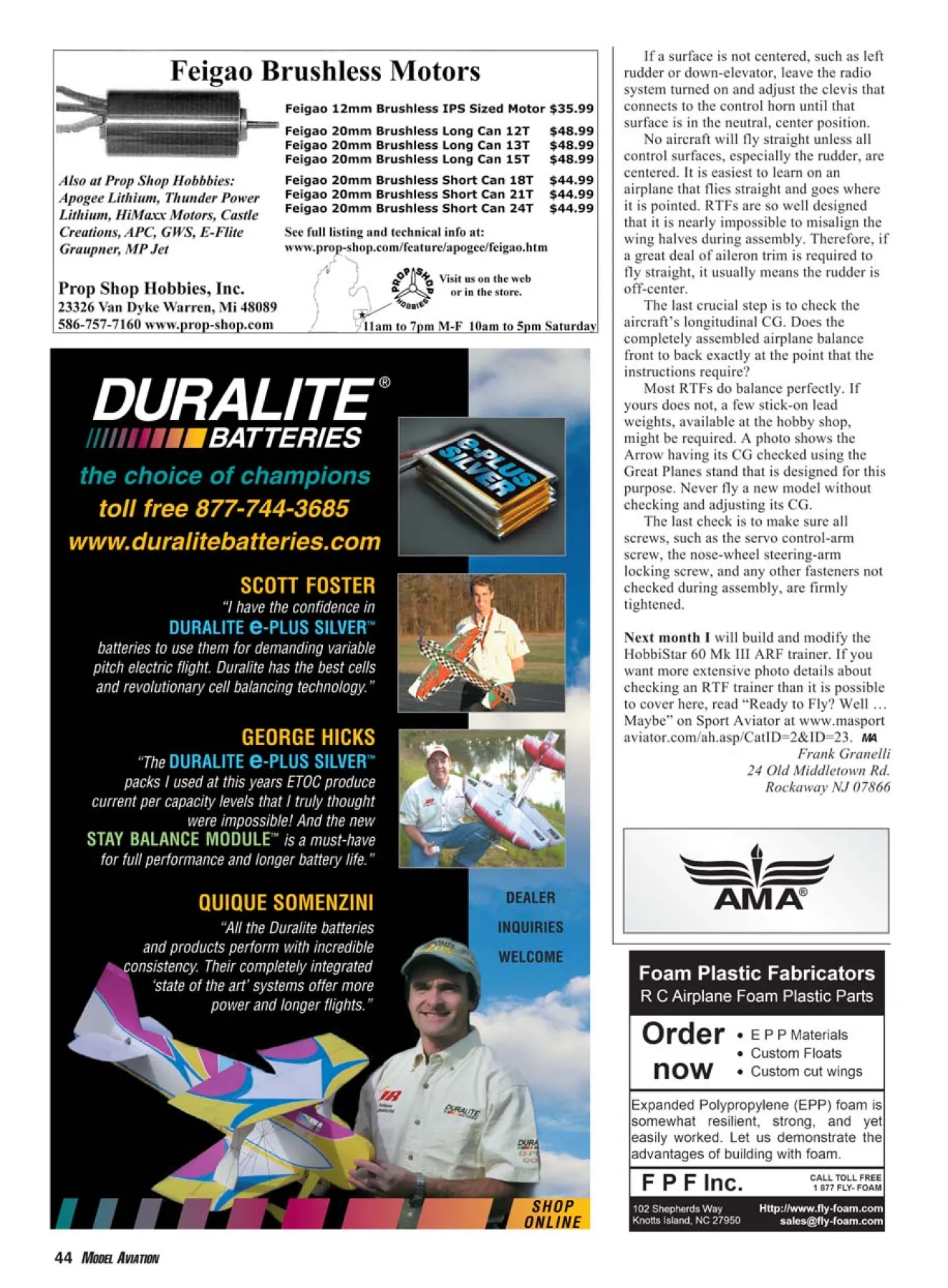

