
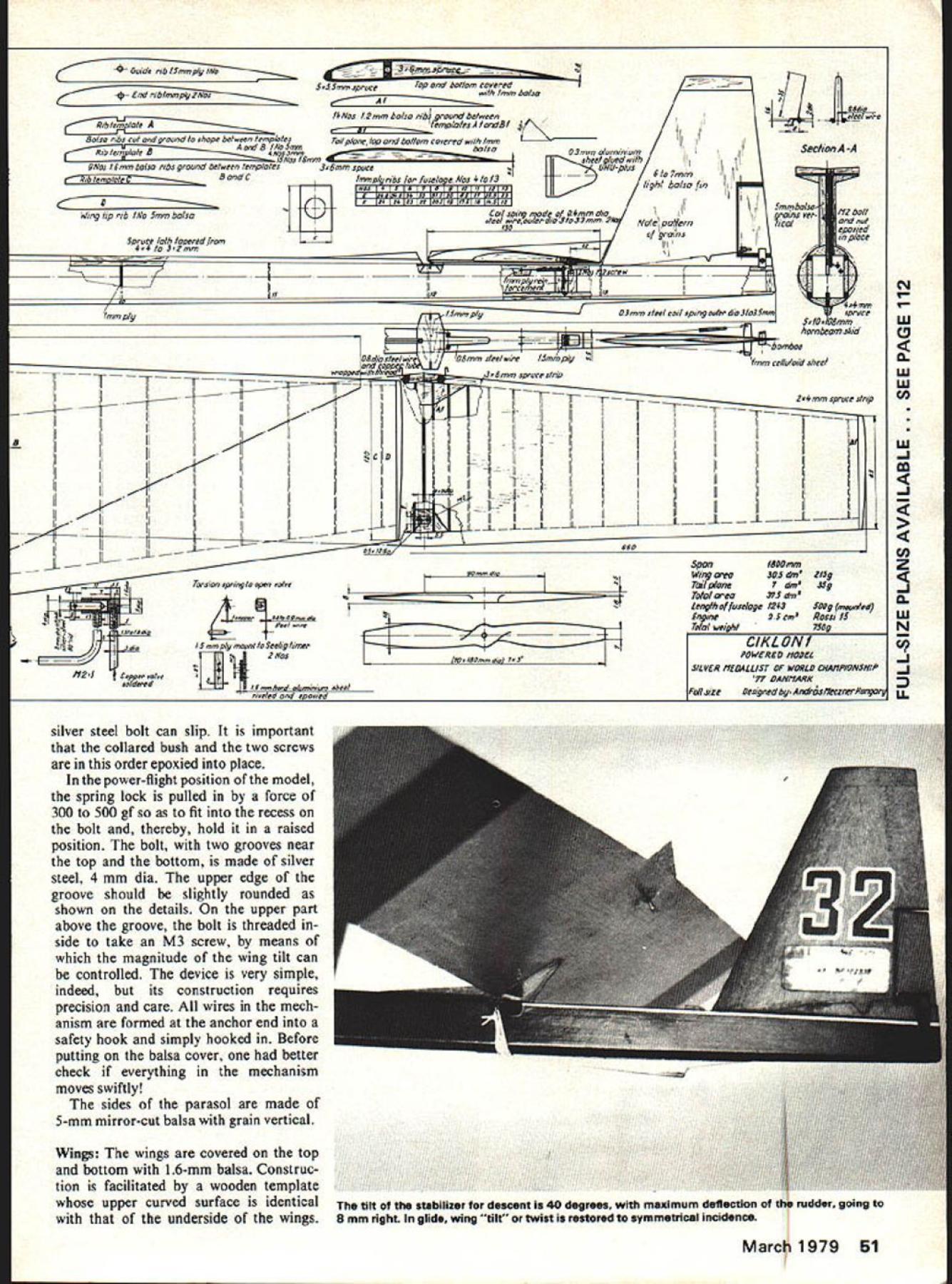
This finest FAI jobs world winner major meets Silver Medalist 1977 World ChampionshipsE Andras Meczner THE Cikion designed following five earlier models latest model preserving style geometry its predecessors size line modern development models MME 31 32 took part World Championship 77 constructed 1975 have proved benevolent right start suffering minor landing injuries National Championship 75 won first place World Champion ship 1975 placed tenth among 42 finalists European Champion ship 1976 model again placed tenth models 31 32 successively won first place Miners Cup competitions between 1975 1977 1977 winner international competition Socialist countries held Yerevan followed World Champi onship Roskilde Denmark Twenty-two competitors qualified final 13 managed get second round 8 us survived final start very satisfying to win silver medal fine model Designer Cikion describes preserving style geometry five earlier Marlcs line modern develop ment Features upward corkscrew flight made possible adjustable wing tilt Before going construction worthwhile deal briefly some basic considerations concerning flying mechanism model During powered flight model acted upon force generated opponent torque propeller results tilt model direction rotation propeller effect becomes pronounced increased speed Normally torque can countered adjustment rudder However way straight climb can tained under varying wind condi tions does permit steady safe climb During decades modeling career have grown increasingly convinced spirally climbing model can become success See eg Conowers USA Lucky Lindy model French Jean Michel European Champion 48 Model Aviation lsvelin launch has part ana parcel FAI flying long time interesting reflect whet vast chenges have come over years rules sought control flight times gadgetry trend now AMA gas Such upward corkscrew flight can attained wings tilted 15 2 degrees ie side toward propeller rotates wing set greater angle inclination horizontal Unfortunately torque thus resulting can very dis advantageous model becomes apt turn over finds difficult stabi lize again come back normal glide CIKLON adverse effect completely offset both powered free flight aid special wing-moving mechanism adjustable relative position wings opposite sides can adjusted will changeable washers put under bolt M 3 See drawing Another novel feature model engine-stopping device prefer simple arrangement silicon rubber pressed down steel spring Simplicity however led crash occasions needle-type shut-off valve used CIKLON re quires precision making faultless operation over years special maintenance well worth extra effort principle operation follows Seelig timer shuts pulls back needle valve position no flow fuel As timer releases valve fuel allowed pass engine thus causing stop immediately opening valve also aided torsional spring end torsion spring threaded through needle valve formed hook connected via steel actuating cord Seelig Timer vertical maneuverability two small M2 size control screws inserted under tail plane fuselage means position angle tail plane can set required powered flight free glide power flight both screws clamped down hammer-head hooks hinged bottom fuselage two hooks actuated separate coil springs left-hand side hook serves free glide control right-hand side hook landing controlas can seen following left hook slips back thus clamp screws ceases hinged tail plane allowed tilt position required free glide As right-hand side clamp also released tail plane swings position inclined 40 degrees horizontal required landing facilitate tilt tail plane desired position U-shaped steel spring anchored top board fuselage used limit tilt tail plane 40 degrees required also prevent wear woodwork thin aluminum plate cut bent shown drawing epoxied underside tail plane piece wire hooked both ends fuselage threaded through thin-walled steel tube cotton threaded glued leading edge tail plane serves hinge Fuselage The two vertical sides made stiff 4-mm balsa reinforced 4 X 4mm spruce strips along edges Upon drying glue both sides reduced thickness towards tail spruce strips have cross-sectional area 4 X 4 mm front against 3 X 2 mm rear work can done best grinding disc Next mount would-be top fuselage balsa board 7-mm thick laid level surface two vertical sides spaced distances corresponding widths ribs land 12 glued Upon drying make slots top board jointing parasol wing sup port making sure its plane strictly line longitudinal axis model Finally grind down top hand give curved surface shown sec tions A-A B-B drawing parasol will mounted rest modelstructure balsa cover completed subsequent work done through open belly model First place home glue numbered fuselage ribs See table drawing fuselage tapered towards rear two sides bevel-jointed form edged tail fin projects through slot bottom fuselage tail-plane control device also housed inside fuselage sides re inforced I-mm plywood axle anchors moving mechanism Maneuvering controlled Seelig timer original device slightly modi fied 41 operations shown picture drawing timer device fastened M2 screw hardaluminum plate Since width timer 28 mm fuselage section 27 mm recess 05 07-mm 2 mm deep should made 4 X 4-mm spruce reinforcing strips accommodate timer Further de tails drawing two hammer-headed hooks used hold down head two M2 screws driven below tail plane made 07 08 copper sheet bent U shape placed 5-mm centers shown details Connected hammer-head hook quickrelease coil spring made 04 05-mm steel wire coiled around bolt 22-mm dia far end spring clasped about axle 12-mm dia spring permanently tensioned force 200 300 gf actuating lines connect lower part hammer-head March1979 49 1977 Silver Medalist powered Rossi 15 turning 25700 wIth homemade hardwood prop Model built mostly balsa pine ribs Andrea Casts own aluminum engine housing uses Seelig timer actuate controls precisely govern its complex flight adjustments F Pm/c em 7 Pressure c/vim B Injector s/ga enne e mA sagaOsmsgS wwd LIe vahw 8 h fiNd P2nmp y ,sb2STiffliPy F-r mm hard ats 0dm sheet33 15/ bamboo ~ZPI 7mm balsa eq __ K4-e-Leg/h II__ Al7mm bulufuse/ape IIi A ___I ___ -4 __ r17K IiII] I IhtIhV4$5ape __A JLA ____ -4 2 F if-- wT IIII]ii IIIIi iiiiIi Th Ii Ii IiII II IIII IitiI IIIiIII iiIIii IIII Ommda4 5s5mmsm7 ft eposied1 nLIm plywood SNrn hard aluacreum tisbe screw No 3Yinp 3/ee/Copper /hrearjed~Idling lube hook timer fastened same way important mechanism moves swiftly lines timer tail plane steel cord fin made balsa sym metrical cross section shown drawing Note pattern grains two hinges moving part aileron made celluloid strips 1-mm thick turn about pin axles Wing Adjusting Mechanism construc tion mechanism contained parasol begins steering balance latter made 1-mm hard-aluminum plate pivots M2 screw tightened double nuts epoxied upright thread bolt cut such length permit smooth movement balance pivot nuts drawn tight Above top board parasol just enough space 06-mm dia steel wire links steering balance L-shaped spring lock spring fastened top board two M2 screws tightened firmly other corner serves pivot looped spring can rotate freely Inserted top board collared copper bush 50 Model Aviation 800 Span MPG Sechon 8-8 student FAI FF will appreciate frontuna amalmaAndras talks wing -ruu actually means wing twist angular setting left pane neing varied ad justment screw See Flight Characteristics text ~lbt55fN 5eTop ba/tomJI eu/h 1mm balsaII bet eeen ~mlale~t4AIas 12mm balsa ribs tf,piate bra/SI a ribs cut a,d ground uhape betioeen emplo 0 r0 p /40 ba/tam covered ,i/h mm m aluminiumSec/ian -A 0/los 16mm balsa ribs ground ke/see, temp C3 6mm sousefjf~S1RiU-plusII RandC ribs /0 fusel oNos 4a 3TIJj2light ba/so fi Cm/sd 0emmdiaI Smmbalsoand nut Wing tip rib INa 5mm balsasleet 033mm- 2Natepa1ern Spruce la/I /aoered fromf grqins 44 Ia 32mm _______PsSrtW 10eut--I,44mmN Imm ply03mm s/eel coil spiny outer dia 3ta3Smmspruce 6. /006mmW hornbeom skid0 06dibs/eelv4r06mm s/eel obse lSmm ply mm celluloid sheet 6mm spruce striloW w TTTTr IIiiIITT24mm spruce strip II II \4f II CDIIi.m AiiII i i i IiIiiIIiiIil~IiII I I II iii.JL.JL -i-4--- _12 i___ LIIILJLJ--- I __000 Span1500mmZ 00,, 5Winy area303 din21Sf Torsion spring/s open as/ce1Tait plane Vg 0 /a/woo1243Sony k7 Enyue2ScmRassit5W Total weiht750yN ____ me.CIKLONI F11 O,asO s /EREDIVOD6L f12tCoSILVER IIEDALCIST OP WORLD ChAIIP/ONS/IIPJ 00 DAt/I/lARK 0 t/size Desngned Arzdro4s/teczrerltungor ad silver steel bolt can slip important collared bush two screws order epoxied place power-flight position model spring lock pulled force 300 500 gf fit recess bolt thereby hold raised position bolt two grooves near top bottom made silver steel 4 mm dia upper edge groove should slightly rounded shown details upper part above groove bolt threaded side take M3 screw means magnitude wing tilt can controlled device very simple indeed its construction requires precision care wires mech anism formed anchor end safety hook simply hooked Before putting balsa cover better check everything mechanism moves swiftly sides parasol made 5-mm mirror-cut balsa grain vertical Wings wings covered top bottom 16-mm balsa Construc tion facilitated wooden template upper curved surface identical underside wings March 1979 51 tilt stabilizer descent 40 degrees maximum deflection rudder going 8 mm right glide wing t restored symmetrical incidence First make two main bearers using 35 X 6-mm spruce strips laid flat tapered towards wing tip have reduced cross-section 35 05 mm flap attached flaps re quire no bearer order fasten two wings gether cotton-threaded hard-aluminum tube 65 mm long 6-mm dia epoxied between main bearers wing work requires great care bores tubes neatly ground polished spring steel bolt 100 mm long bent secure required dihedral fits tightly leading edge made 3 spruce strip no reinforcement trailing edge bottom balsa sheet bevelled glued top sheet shown drawing chesterton Editor sorry section ribs made half pieces Start mount ing wing pinning down template balsa sheet used bottom mid-piece wing balsa sheet cut some 10 mm wider leading edge 3 mm wider trailing edge final dimen sions Stick piece adhesive tape under rib template prevent ribs being glued balsa sheet made up narrow strips buttjointed glued together flat surface order prevent warp balsa sheet again oversized lengthwise some 10 20mm flap prepared separately tached mid-part joint bevelled give obtuse angle required convenient use V-shaped template purpose apply some glue joint sur face after repeat Editor double glue fit two parts gether fixing temporarily pin same time also glue 3-mm balsa rib joint position main girder glued followed balsa ribs order marked drawing mid-part complete glue reinforcing strip leading edge ribs flap spruce strip ground desired cross section beforehand bevel-jointed glued leading edge strip mid-part use slow-setting glue entire balsa cover may jointed glued go However use celluloidglue may advantageous order minimize weight has work fast flap joint balsa covers should obviously bevelled glued right across both top bottom work worth doing properly ensure durability wings mounted wing has left dry template least two days Upon removal few days rest will very useful before completed wing trimmed final dimensions midpart provided 12-mm plywood rib inner end wing tip covered 5-mm balsa rib same template used mounting both left- right-hand side wing template having common central part 70-cm long either left right hand side flap template can bolted has proven very useful Stabilizer mounting tail plane done similar manner using flat board template bottom cover 08 I-mm thick pinned down first prepared spruce leading edge strip glued spruce strip fixed several places pins Epoxied leading edge cotton-threaded copper steel tube piece steel wire passing through hooked both ends se cures fastening tail plane fuselate means rubber ties ribs placed home glued sequence numbering shown drawing ribs made grinding shape appropriate number plywood plates held between templates Al Bl mounting upper cover starts leading edge must care ful glue since too much increases weight also tends contract thin balsa cover Final trim ming polishing tail plane can done after few days drying construction model completed advisable rub entire surface over once fine sand paper order obtain perfectly smooth clean surface vital assemble model check controls before finish applied still pos sibility readjustment correction eg top board parasol can sandpapered match dihedral re quired Covering model covered Japanese paper doped Cellon varnish applied 6 8 layers Before application last few layers surface gently rubbed fine-grade sandpaper fuselage coated floor varnish using material sparsely avoid undue weight Before test flying model ac curate trimming very important purpose make wooden cradle fasten fore rear fuselage rubber ties fuselage must absolutely horizontal Place protractor against underside wings also tail plane fix rubber bands hang plumbbob center protractor measure deflection plumbline several sections Compute arithmetical mean measured data way unnoticed twist wings can revealed data flying characteristics given should also re garded averages weight wing sandpapered uncoated160 170 g weight tail plane sandpapered un 52 Model Aviation Stabilizer removed show details its mounting General captions just cant justice Andras machinewe urge very careful reading adjustments sequence operations Note example says end free glide stab tilt rudder deflections stated launches 70 degrees horizontal 5 10 degrees right wind direction ship executing 1-1/2 turns spiral near vertical climb coated25 30 g Flying Characteristics Powered Flight Tilt right wing left wing tail plane means model rises position angle right wing twisted relative left wing twist wings can set re quired value moving up down head adjusting bolt wingmoving mechanism built parasol advisable either prepare number bolts various lengths provide set washers single bolt Seelig timer switched lock re leases allowing bolt drop recess rubber ties pull wing down position required normal max deflection rudder 8 mm right Fuel fed engine under pres sure via pipe marked C tank located engine block Through tube T engine compression re-fed fuel tank overpressurized ar rangement permits smooth operation engine Soldered onto fuel tank shut-off valve As needle valve released timer excess amount fuel allowed pass via pipe B engine causing stop immediately tank replenished through M3 tube stopped M3 cap-screw essential both valve lid filling mouth perfectly sealed advisable immerse entire tank assembly glass petrol put under First holding model hand engine running check operation mechanisms wing tailplane rudder engine shut-off equally vital Timing should also work perfectly first start may come 4-s powered flight low throttle Second start 4-s powered flight full throttle basis observations may carry out start start necessary corrections horizontal control wing-twist etc Nor mally few tenths millimeters model exhibits smooth dependable performance can make additional starts gradually increasing duration powered flight Free glide should scheduled 5 10 seconds upon stopping engine Properly tested trimmed model can now flown model held slightly free glide rudder slightly deflected plane fin some 05 mm right Seelig timer modified give 4-plus-i operations sequence 1 release rudder 2 5 seconds later stops engine 3 after another 5 seconds releases tail plane 4 1 12 seconds after engine stops wing twist restored glide configuration Uses pressurized tankshut-off soldered top tank may seen pic front endwith positive flood off Glide Tilt both right left wing tail plane 30 ie model glides angle 3 330 center gravity located dis tance 120 mm back leading edge wing Any adjustment CG can made manipulating weight cast nose block eg filing sequence operation timer follows first releases rudder 05 seconds later stops engine After another 05 seconds hold tail plane released finally 12 seconds stop engine wing twist offset duration free glide can always adjusted accord ing requirements test flight completion end free glide tilt-up tail plane approx 400 pressure pump check leak start engine remove mipolan Editor sorryagain tube tube T let engine run idle Fuelling also carried out same position replace mipolan tube tube T after two pulls starter engine must start too much fuel flows engine mipolan tube must removed instantly thus ex cess pressure ceases no fuel fed engine mipolan tube should handled pincers order avoid damage time time aged pipes should replaced Test Flying unnecessary make trial free glide provided adjustments checks have carried out properly tilted can launched throwing javelin 70 degrees horizontal against wind some 5 10 degrees right wind direction model rising near vertically covers 1 1 5 spiral during 7 seconds powered flight according FAT well-trimmed model passes smoothly powered flight free glide few hints trimming rise during powered flight too flat model tends circle tightly right relative twist wings too small should increased putting additional 05 mm washers beneath bolt raises left wing end powered flight model passes straight rise tends circle Continued page 106 March 1979 53 RADIO REMOTE CONTROL MODELS* PRESSURE SENSITIVE TRIM DECALS PC-iSPITFIREPT 30013 x 22 Ir 2 Scolioped Red Whre o,d Blue RC-2T-28 BP130023522 rh 2Sl Red RC-3FW 190 0-9PT3OWi 522 ocrI 2Honn Red RC-4WACO YMT-3PT 30043 622 rh 2 Funnels Red PC-SDUELLISS 2/40PT 35055 58 h sqcoes Block end Cmeor RC-6CESSNA 1821 3aP3 68 WkreSo, 7 sold lourlne PRESSURE SENSITIVE DECALSPT 311073 520 Wrp Sros S oId 5 ourlOp PD-21X11RAF DECAL LargePT33 6 22 *,I 2 S*,Is Geen P0 2002U S NAVY DECAL LargePT 30093% 5 22 h 2 Hons Green P0203GERMAN WW II Large APT 301o3 5 22 crh 2 Punnein Green P0-21304CIvILIAN DECAL SETPT 30113 5 22 rh 2 S,In IRIuCI P0-2005cLIFTWAFFE WW Large APT 30123 5 22 ,, RIue P0-2006LUETWAFFEE WW Smoll APT 3033 5 22 .t 2 Punnels Rice P02007LUETWAFFEE WW (Large B ICA PLASTIC PARTS P0-2006LUFTWAFFEE WW LargePP uce WACO COWL & 14 BLISTERS P0-2009LUETWAFFEE WW (SmallPP2WACO WHEEL PANTS P0-2010US WW (LargePP3WACO BLISTERS ONLY (4 P02011US WW II SmallP110534FW 90 COWL P0-2012US WW (LargePesFW 90 CANOPY P0-2013US WW (Small11511-28 COWL l3pecesl P0-2014RAF WW II SmallPF7-28 CANOPY SET 2 preces P0-2015RAP WW (Largecccna7-28 REAR CANOPY P0-2016RAP WW Smallresiec7-28 FRONT WINDSHIELD P0-2017NCAM 1-0 3 blk 5hT- -SPITFIRE CANOPY P0-208NCAM 1-0 2 blk TFIRE BUBBLE CANOPY P02019NCAM 0 DUELLIST CANOPY P0-2020AIRCRAFT STENCILS-~pJ A 82 WNDSHELD SET 4 pieces P0-202US WW (Small Blue CESSNA 82 COWL 2 pece P02022RAE WW (Largepv4osj NA 82 WHEEL PANTS 3 piece SCALE SPINNERS 3" FW-90 NylanPRODUCTS P5550 3P-5 P-39Nylae2657 NE 188th ST MIAMI FLORIDA 33180 PSSnJ33 P40 / SpTfreNyIor305 935 1436 PS 5504 3" FW-190NylonChrameNNOVATIONS IN MODElING PS 50053 P 51 P 39-Nyon-Chrome P5510303 P 4O/Splfre-Nyon-ChromeAvalabe 90 days Look products consistently running over 200 phe nomenon result new engines improvement set upwhich have already pointed out must An engine carefully put together test run bench failing come up ex pectations should scrapped test circle might show performance never dreamed Dubby Jett can testify David Layman took Dubs large box discarded cylinders pistons engine outran Dub Na tionals set new speed record engine 500 1000 rpm off what already have try might like what expect happen year First thing expect see inyour local hobby shop crease number contestants Class D Rossi excellent D-class engine available ring version ABC have heard nothing praise engine speed free flight RC boats everyone agrees surprised output engine right out box well-made well-designed stock engine what event has needed 5 6 years mini-pipes will good run will help cut down expense class yield fun excitement Formula 40 will continue popular event think speeds class will higher ever lot new faces emerging winners circle Nitromethane synthetic oil will harder harder come price will probably increase both fact seems telling probably should going alcohol move could make contests challenging time time will guest editors write about opinions recommendations hope doing will inspire people write about what would like read Gene Hempel 301 N Yale Dr Gar land TX 75042 Ciklon/Meczner continued page 53 left left adjusting screw tail plane should raised 02 03 mm order increase overall position angle model timing actuating rudder might also brought forward does help may try reduce wing twist Raise right-hand side adjusting screw tail plane controls free flight such extent ie increase position angle model glides safely gusts thermic weather conditions Fairchild/Clapp continued page 58 Fairchild test pilot Dick Depews log gives different test flight sequence Ac cording Curtiss machine first flew June 12 1927 Fairchild Surveys Canada aircraft June 20 Department Commerce machine June 30 chronology probably accurate Fairchild history somewhat complicated point fact FC-2 soon built Canada under license Canadian Vickers Ltd Mon treal built 12 FC-2 Razor Backs before Fairchild license withdrawn Fairchild Aviation Limited Longueuil Quebec formed first aircraft built new company early 71 series explained later FC-2 soon followed Pratt & Whitney Wasp powered FC-2W prototype wing span creased 50 feet jury struts added longer wing struts Otherwise air frame remained basically same doing lateral control became less effective because extended wing tip drag Freize-type ailerons stalled correction Ten FC-2Ws built after proto type second produced sold Bell Telephone Laboratories aircraft became instrumental devel opment air-to-ground two-way radio helpful newly forming airlines FC-2W discontinued favor FC-2W2 same airframe two feet added fuse106 Model Aviation

Edition: Model Aviation - 1979/03
Page Numbers: 48, 49, 50, 51, 52, 53, 106

Edition: Model Aviation - 1979/03
Page Numbers: 48, 49, 50, 51, 52, 53, 106
This finest FAI jobs world winner major meets Silver Medalist 1977 World ChampionshipsE Andras Meczner THE Cikion designed following five earlier models latest model preserving style geometry its predecessors size line modern development models MME 31 32 took part World Championship 77 constructed 1975 have proved benevolent right start suffering minor landing injuries National Championship 75 won first place World Champion ship 1975 placed tenth among 42 finalists European Champion ship 1976 model again placed tenth models 31 32 successively won first place Miners Cup competitions between 1975 1977 1977 winner international competition Socialist countries held Yerevan followed World Champi onship Roskilde Denmark Twenty-two competitors qualified final 13 managed get second round 8 us survived final start very satisfying to win silver medal fine model Designer Cikion describes preserving style geometry five earlier Marlcs line modern develop ment Features upward corkscrew flight made possible adjustable wing tilt Before going construction worthwhile deal briefly some basic considerations concerning flying mechanism model During powered flight model acted upon force generated opponent torque propeller results tilt model direction rotation propeller effect becomes pronounced increased speed Normally torque can countered adjustment rudder However way straight climb can tained under varying wind condi tions does permit steady safe climb During decades modeling career have grown increasingly convinced spirally climbing model can become success See eg Conowers USA Lucky Lindy model French Jean Michel European Champion 48 Model Aviation lsvelin launch has part ana parcel FAI flying long time interesting reflect whet vast chenges have come over years rules sought control flight times gadgetry trend now AMA gas Such upward corkscrew flight can attained wings tilted 15 2 degrees ie side toward propeller rotates wing set greater angle inclination horizontal Unfortunately torque thus resulting can very dis advantageous model becomes apt turn over finds difficult stabi lize again come back normal glide CIKLON adverse effect completely offset both powered free flight aid special wing-moving mechanism adjustable relative position wings opposite sides can adjusted will changeable washers put under bolt M 3 See drawing Another novel feature model engine-stopping device prefer simple arrangement silicon rubber pressed down steel spring Simplicity however led crash occasions needle-type shut-off valve used CIKLON re quires precision making faultless operation over years special maintenance well worth extra effort principle operation follows Seelig timer shuts pulls back needle valve position no flow fuel As timer releases valve fuel allowed pass engine thus causing stop immediately opening valve also aided torsional spring end torsion spring threaded through needle valve formed hook connected via steel actuating cord Seelig Timer vertical maneuverability two small M2 size control screws inserted under tail plane fuselage means position angle tail plane can set required powered flight free glide power flight both screws clamped down hammer-head hooks hinged bottom fuselage two hooks actuated separate coil springs left-hand side hook serves free glide control right-hand side hook landing controlas can seen following left hook slips back thus clamp screws ceases hinged tail plane allowed tilt position required free glide As right-hand side clamp also released tail plane swings position inclined 40 degrees horizontal required landing facilitate tilt tail plane desired position U-shaped steel spring anchored top board fuselage used limit tilt tail plane 40 degrees required also prevent wear woodwork thin aluminum plate cut bent shown drawing epoxied underside tail plane piece wire hooked both ends fuselage threaded through thin-walled steel tube cotton threaded glued leading edge tail plane serves hinge Fuselage The two vertical sides made stiff 4-mm balsa reinforced 4 X 4mm spruce strips along edges Upon drying glue both sides reduced thickness towards tail spruce strips have cross-sectional area 4 X 4 mm front against 3 X 2 mm rear work can done best grinding disc Next mount would-be top fuselage balsa board 7-mm thick laid level surface two vertical sides spaced distances corresponding widths ribs land 12 glued Upon drying make slots top board jointing parasol wing sup port making sure its plane strictly line longitudinal axis model Finally grind down top hand give curved surface shown sec tions A-A B-B drawing parasol will mounted rest modelstructure balsa cover completed subsequent work done through open belly model First place home glue numbered fuselage ribs See table drawing fuselage tapered towards rear two sides bevel-jointed form edged tail fin projects through slot bottom fuselage tail-plane control device also housed inside fuselage sides re inforced I-mm plywood axle anchors moving mechanism Maneuvering controlled Seelig timer original device slightly modi fied 41 operations shown picture drawing timer device fastened M2 screw hardaluminum plate Since width timer 28 mm fuselage section 27 mm recess 05 07-mm 2 mm deep should made 4 X 4-mm spruce reinforcing strips accommodate timer Further de tails drawing two hammer-headed hooks used hold down head two M2 screws driven below tail plane made 07 08 copper sheet bent U shape placed 5-mm centers shown details Connected hammer-head hook quickrelease coil spring made 04 05-mm steel wire coiled around bolt 22-mm dia far end spring clasped about axle 12-mm dia spring permanently tensioned force 200 300 gf actuating lines connect lower part hammer-head March1979 49 1977 Silver Medalist powered Rossi 15 turning 25700 wIth homemade hardwood prop Model built mostly balsa pine ribs Andrea Casts own aluminum engine housing uses Seelig timer actuate controls precisely govern its complex flight adjustments F Pm/c em 7 Pressure c/vim B Injector s/ga enne e mA sagaOsmsgS wwd LIe vahw 8 h fiNd P2nmp y ,sb2STiffliPy F-r mm hard ats 0dm sheet33 15/ bamboo ~ZPI 7mm balsa eq __ K4-e-Leg/h II__ Al7mm bulufuse/ape IIi A ___I ___ -4 __ r17K IiII] I IhtIhV4$5ape __A JLA ____ -4 2 F if-- wT IIII]ii IIIIi iiiiIi Th Ii Ii IiII II IIII IitiI IIIiIII iiIIii IIII Ommda4 5s5mmsm7 ft eposied1 nLIm plywood SNrn hard aluacreum tisbe screw No 3Yinp 3/ee/Copper /hrearjed~Idling lube hook timer fastened same way important mechanism moves swiftly lines timer tail plane steel cord fin made balsa sym metrical cross section shown drawing Note pattern grains two hinges moving part aileron made celluloid strips 1-mm thick turn about pin axles Wing Adjusting Mechanism construc tion mechanism contained parasol begins steering balance latter made 1-mm hard-aluminum plate pivots M2 screw tightened double nuts epoxied upright thread bolt cut such length permit smooth movement balance pivot nuts drawn tight Above top board parasol just enough space 06-mm dia steel wire links steering balance L-shaped spring lock spring fastened top board two M2 screws tightened firmly other corner serves pivot looped spring can rotate freely Inserted top board collared copper bush 50 Model Aviation 800 Span MPG Sechon 8-8 student FAI FF will appreciate frontuna amalmaAndras talks wing -ruu actually means wing twist angular setting left pane neing varied ad justment screw See Flight Characteristics text ~lbt55fN 5eTop ba/tomJI eu/h 1mm balsaII bet eeen ~mlale~t4AIas 12mm balsa ribs tf,piate bra/SI a ribs cut a,d ground uhape betioeen emplo 0 r0 p /40 ba/tam covered ,i/h mm m aluminiumSec/ian -A 0/los 16mm balsa ribs ground ke/see, temp C3 6mm sousefjf~S1RiU-plusII RandC ribs /0 fusel oNos 4a 3TIJj2light ba/so fi Cm/sd 0emmdiaI Smmbalsoand nut Wing tip rib INa 5mm balsasleet 033mm- 2Natepa1ern Spruce la/I /aoered fromf grqins 44 Ia 32mm _______PsSrtW 10eut--I,44mmN Imm ply03mm s/eel coil spiny outer dia 3ta3Smmspruce 6. /006mmW hornbeom skid0 06dibs/eelv4r06mm s/eel obse lSmm ply mm celluloid sheet 6mm spruce striloW w TTTTr IIiiIITT24mm spruce strip II II \4f II CDIIi.m AiiII i i i IiIiiIIiiIil~IiII I I II iii.JL.JL -i-4--- _12 i___ LIIILJLJ--- I __000 Span1500mmZ 00,, 5Winy area303 din21Sf Torsion spring/s open as/ce1Tait plane Vg 0 /a/woo1243Sony k7 Enyue2ScmRassit5W Total weiht750yN ____ me.CIKLONI F11 O,asO s /EREDIVOD6L f12tCoSILVER IIEDALCIST OP WORLD ChAIIP/ONS/IIPJ 00 DAt/I/lARK 0 t/size Desngned Arzdro4s/teczrerltungor ad silver steel bolt can slip important collared bush two screws order epoxied place power-flight position model spring lock pulled force 300 500 gf fit recess bolt thereby hold raised position bolt two grooves near top bottom made silver steel 4 mm dia upper edge groove should slightly rounded shown details upper part above groove bolt threaded side take M3 screw means magnitude wing tilt can controlled device very simple indeed its construction requires precision care wires mech anism formed anchor end safety hook simply hooked Before putting balsa cover better check everything mechanism moves swiftly sides parasol made 5-mm mirror-cut balsa grain vertical Wings wings covered top bottom 16-mm balsa Construc tion facilitated wooden template upper curved surface identical underside wings March 1979 51 tilt stabilizer descent 40 degrees maximum deflection rudder going 8 mm right glide wing t restored symmetrical incidence First make two main bearers using 35 X 6-mm spruce strips laid flat tapered towards wing tip have reduced cross-section 35 05 mm flap attached flaps re quire no bearer order fasten two wings gether cotton-threaded hard-aluminum tube 65 mm long 6-mm dia epoxied between main bearers wing work requires great care bores tubes neatly ground polished spring steel bolt 100 mm long bent secure required dihedral fits tightly leading edge made 3 spruce strip no reinforcement trailing edge bottom balsa sheet bevelled glued top sheet shown drawing chesterton Editor sorry section ribs made half pieces Start mount ing wing pinning down template balsa sheet used bottom mid-piece wing balsa sheet cut some 10 mm wider leading edge 3 mm wider trailing edge final dimen sions Stick piece adhesive tape under rib template prevent ribs being glued balsa sheet made up narrow strips buttjointed glued together flat surface order prevent warp balsa sheet again oversized lengthwise some 10 20mm flap prepared separately tached mid-part joint bevelled give obtuse angle required convenient use V-shaped template purpose apply some glue joint sur face after repeat Editor double glue fit two parts gether fixing temporarily pin same time also glue 3-mm balsa rib joint position main girder glued followed balsa ribs order marked drawing mid-part complete glue reinforcing strip leading edge ribs flap spruce strip ground desired cross section beforehand bevel-jointed glued leading edge strip mid-part use slow-setting glue entire balsa cover may jointed glued go However use celluloidglue may advantageous order minimize weight has work fast flap joint balsa covers should obviously bevelled glued right across both top bottom work worth doing properly ensure durability wings mounted wing has left dry template least two days Upon removal few days rest will very useful before completed wing trimmed final dimensions midpart provided 12-mm plywood rib inner end wing tip covered 5-mm balsa rib same template used mounting both left- right-hand side wing template having common central part 70-cm long either left right hand side flap template can bolted has proven very useful Stabilizer mounting tail plane done similar manner using flat board template bottom cover 08 I-mm thick pinned down first prepared spruce leading edge strip glued spruce strip fixed several places pins Epoxied leading edge cotton-threaded copper steel tube piece steel wire passing through hooked both ends se cures fastening tail plane fuselate means rubber ties ribs placed home glued sequence numbering shown drawing ribs made grinding shape appropriate number plywood plates held between templates Al Bl mounting upper cover starts leading edge must care ful glue since too much increases weight also tends contract thin balsa cover Final trim ming polishing tail plane can done after few days drying construction model completed advisable rub entire surface over once fine sand paper order obtain perfectly smooth clean surface vital assemble model check controls before finish applied still pos sibility readjustment correction eg top board parasol can sandpapered match dihedral re quired Covering model covered Japanese paper doped Cellon varnish applied 6 8 layers Before application last few layers surface gently rubbed fine-grade sandpaper fuselage coated floor varnish using material sparsely avoid undue weight Before test flying model ac curate trimming very important purpose make wooden cradle fasten fore rear fuselage rubber ties fuselage must absolutely horizontal Place protractor against underside wings also tail plane fix rubber bands hang plumbbob center protractor measure deflection plumbline several sections Compute arithmetical mean measured data way unnoticed twist wings can revealed data flying characteristics given should also re garded averages weight wing sandpapered uncoated160 170 g weight tail plane sandpapered un 52 Model Aviation Stabilizer removed show details its mounting General captions just cant justice Andras machinewe urge very careful reading adjustments sequence operations Note example says end free glide stab tilt rudder deflections stated launches 70 degrees horizontal 5 10 degrees right wind direction ship executing 1-1/2 turns spiral near vertical climb coated25 30 g Flying Characteristics Powered Flight Tilt right wing left wing tail plane means model rises position angle right wing twisted relative left wing twist wings can set re quired value moving up down head adjusting bolt wingmoving mechanism built parasol advisable either prepare number bolts various lengths provide set washers single bolt Seelig timer switched lock re leases allowing bolt drop recess rubber ties pull wing down position required normal max deflection rudder 8 mm right Fuel fed engine under pres sure via pipe marked C tank located engine block Through tube T engine compression re-fed fuel tank overpressurized ar rangement permits smooth operation engine Soldered onto fuel tank shut-off valve As needle valve released timer excess amount fuel allowed pass via pipe B engine causing stop immediately tank replenished through M3 tube stopped M3 cap-screw essential both valve lid filling mouth perfectly sealed advisable immerse entire tank assembly glass petrol put under First holding model hand engine running check operation mechanisms wing tailplane rudder engine shut-off equally vital Timing should also work perfectly first start may come 4-s powered flight low throttle Second start 4-s powered flight full throttle basis observations may carry out start start necessary corrections horizontal control wing-twist etc Nor mally few tenths millimeters model exhibits smooth dependable performance can make additional starts gradually increasing duration powered flight Free glide should scheduled 5 10 seconds upon stopping engine Properly tested trimmed model can now flown model held slightly free glide rudder slightly deflected plane fin some 05 mm right Seelig timer modified give 4-plus-i operations sequence 1 release rudder 2 5 seconds later stops engine 3 after another 5 seconds releases tail plane 4 1 12 seconds after engine stops wing twist restored glide configuration Uses pressurized tankshut-off soldered top tank may seen pic front endwith positive flood off Glide Tilt both right left wing tail plane 30 ie model glides angle 3 330 center gravity located dis tance 120 mm back leading edge wing Any adjustment CG can made manipulating weight cast nose block eg filing sequence operation timer follows first releases rudder 05 seconds later stops engine After another 05 seconds hold tail plane released finally 12 seconds stop engine wing twist offset duration free glide can always adjusted accord ing requirements test flight completion end free glide tilt-up tail plane approx 400 pressure pump check leak start engine remove mipolan Editor sorryagain tube tube T let engine run idle Fuelling also carried out same position replace mipolan tube tube T after two pulls starter engine must start too much fuel flows engine mipolan tube must removed instantly thus ex cess pressure ceases no fuel fed engine mipolan tube should handled pincers order avoid damage time time aged pipes should replaced Test Flying unnecessary make trial free glide provided adjustments checks have carried out properly tilted can launched throwing javelin 70 degrees horizontal against wind some 5 10 degrees right wind direction model rising near vertically covers 1 1 5 spiral during 7 seconds powered flight according FAT well-trimmed model passes smoothly powered flight free glide few hints trimming rise during powered flight too flat model tends circle tightly right relative twist wings too small should increased putting additional 05 mm washers beneath bolt raises left wing end powered flight model passes straight rise tends circle Continued page 106 March 1979 53 RADIO REMOTE CONTROL MODELS* PRESSURE SENSITIVE TRIM DECALS PC-iSPITFIREPT 30013 x 22 Ir 2 Scolioped Red Whre o,d Blue RC-2T-28 BP130023522 rh 2Sl Red RC-3FW 190 0-9PT3OWi 522 ocrI 2Honn Red RC-4WACO YMT-3PT 30043 622 rh 2 Funnels Red PC-SDUELLISS 2/40PT 35055 58 h sqcoes Block end Cmeor RC-6CESSNA 1821 3aP3 68 WkreSo, 7 sold lourlne PRESSURE SENSITIVE DECALSPT 311073 520 Wrp Sros S oId 5 ourlOp PD-21X11RAF DECAL LargePT33 6 22 *,I 2 S*,Is Geen P0 2002U S NAVY DECAL LargePT 30093% 5 22 h 2 Hons Green P0203GERMAN WW II Large APT 301o3 5 22 crh 2 Punnein Green P0-21304CIvILIAN DECAL SETPT 30113 5 22 rh 2 S,In IRIuCI P0-2005cLIFTWAFFE WW Large APT 30123 5 22 ,, RIue P0-2006LUETWAFFEE WW Smoll APT 3033 5 22 .t 2 Punnels Rice P02007LUETWAFFEE WW (Large B ICA PLASTIC PARTS P0-2006LUFTWAFFEE WW LargePP uce WACO COWL & 14 BLISTERS P0-2009LUETWAFFEE WW (SmallPP2WACO WHEEL PANTS P0-2010US WW (LargePP3WACO BLISTERS ONLY (4 P02011US WW II SmallP110534FW 90 COWL P0-2012US WW (LargePesFW 90 CANOPY P0-2013US WW (Small11511-28 COWL l3pecesl P0-2014RAF WW II SmallPF7-28 CANOPY SET 2 preces P0-2015RAP WW (Largecccna7-28 REAR CANOPY P0-2016RAP WW Smallresiec7-28 FRONT WINDSHIELD P0-2017NCAM 1-0 3 blk 5hT- -SPITFIRE CANOPY P0-208NCAM 1-0 2 blk TFIRE BUBBLE CANOPY P02019NCAM 0 DUELLIST CANOPY P0-2020AIRCRAFT STENCILS-~pJ A 82 WNDSHELD SET 4 pieces P0-202US WW (Small Blue CESSNA 82 COWL 2 pece P02022RAE WW (Largepv4osj NA 82 WHEEL PANTS 3 piece SCALE SPINNERS 3" FW-90 NylanPRODUCTS P5550 3P-5 P-39Nylae2657 NE 188th ST MIAMI FLORIDA 33180 PSSnJ33 P40 / SpTfreNyIor305 935 1436 PS 5504 3" FW-190NylonChrameNNOVATIONS IN MODElING PS 50053 P 51 P 39-Nyon-Chrome P5510303 P 4O/Splfre-Nyon-ChromeAvalabe 90 days Look products consistently running over 200 phe nomenon result new engines improvement set upwhich have already pointed out must An engine carefully put together test run bench failing come up ex pectations should scrapped test circle might show performance never dreamed Dubby Jett can testify David Layman took Dubs large box discarded cylinders pistons engine outran Dub Na tionals set new speed record engine 500 1000 rpm off what already have try might like what expect happen year First thing expect see inyour local hobby shop crease number contestants Class D Rossi excellent D-class engine available ring version ABC have heard nothing praise engine speed free flight RC boats everyone agrees surprised output engine right out box well-made well-designed stock engine what event has needed 5 6 years mini-pipes will good run will help cut down expense class yield fun excitement Formula 40 will continue popular event think speeds class will higher ever lot new faces emerging winners circle Nitromethane synthetic oil will harder harder come price will probably increase both fact seems telling probably should going alcohol move could make contests challenging time time will guest editors write about opinions recommendations hope doing will inspire people write about what would like read Gene Hempel 301 N Yale Dr Gar land TX 75042 Ciklon/Meczner continued page 53 left left adjusting screw tail plane should raised 02 03 mm order increase overall position angle model timing actuating rudder might also brought forward does help may try reduce wing twist Raise right-hand side adjusting screw tail plane controls free flight such extent ie increase position angle model glides safely gusts thermic weather conditions Fairchild/Clapp continued page 58 Fairchild test pilot Dick Depews log gives different test flight sequence Ac cording Curtiss machine first flew June 12 1927 Fairchild Surveys Canada aircraft June 20 Department Commerce machine June 30 chronology probably accurate Fairchild history somewhat complicated point fact FC-2 soon built Canada under license Canadian Vickers Ltd Mon treal built 12 FC-2 Razor Backs before Fairchild license withdrawn Fairchild Aviation Limited Longueuil Quebec formed first aircraft built new company early 71 series explained later FC-2 soon followed Pratt & Whitney Wasp powered FC-2W prototype wing span creased 50 feet jury struts added longer wing struts Otherwise air frame remained basically same doing lateral control became less effective because extended wing tip drag Freize-type ailerons stalled correction Ten FC-2Ws built after proto type second produced sold Bell Telephone Laboratories aircraft became instrumental devel opment air-to-ground two-way radio helpful newly forming airlines FC-2W discontinued favor FC-2W2 same airframe two feet added fuse106 Model Aviation

Edition: Model Aviation - 1979/03
Page Numbers: 48, 49, 50, 51, 52, 53, 106
This finest FAI jobs world winner major meets Silver Medalist 1977 World ChampionshipsE Andras Meczner THE Cikion designed following five earlier models latest model preserving style geometry its predecessors size line modern development models MME 31 32 took part World Championship 77 constructed 1975 have proved benevolent right start suffering minor landing injuries National Championship 75 won first place World Champion ship 1975 placed tenth among 42 finalists European Champion ship 1976 model again placed tenth models 31 32 successively won first place Miners Cup competitions between 1975 1977 1977 winner international competition Socialist countries held Yerevan followed World Champi onship Roskilde Denmark Twenty-two competitors qualified final 13 managed get second round 8 us survived final start very satisfying to win silver medal fine model Designer Cikion describes preserving style geometry five earlier Marlcs line modern develop ment Features upward corkscrew flight made possible adjustable wing tilt Before going construction worthwhile deal briefly some basic considerations concerning flying mechanism model During powered flight model acted upon force generated opponent torque propeller results tilt model direction rotation propeller effect becomes pronounced increased speed Normally torque can countered adjustment rudder However way straight climb can tained under varying wind condi tions does permit steady safe climb During decades modeling career have grown increasingly convinced spirally climbing model can become success See eg Conowers USA Lucky Lindy model French Jean Michel European Champion 48 Model Aviation lsvelin launch has part ana parcel FAI flying long time interesting reflect whet vast chenges have come over years rules sought control flight times gadgetry trend now AMA gas Such upward corkscrew flight can attained wings tilted 15 2 degrees ie side toward propeller rotates wing set greater angle inclination horizontal Unfortunately torque thus resulting can very dis advantageous model becomes apt turn over finds difficult stabi lize again come back normal glide CIKLON adverse effect completely offset both powered free flight aid special wing-moving mechanism adjustable relative position wings opposite sides can adjusted will changeable washers put under bolt M 3 See drawing Another novel feature model engine-stopping device prefer simple arrangement silicon rubber pressed down steel spring Simplicity however led crash occasions needle-type shut-off valve used CIKLON re quires precision making faultless operation over years special maintenance well worth extra effort principle operation follows Seelig timer shuts pulls back needle valve position no flow fuel As timer releases valve fuel allowed pass engine thus causing stop immediately opening valve also aided torsional spring end torsion spring threaded through needle valve formed hook connected via steel actuating cord Seelig Timer vertical maneuverability two small M2 size control screws inserted under tail plane fuselage means position angle tail plane can set required powered flight free glide power flight both screws clamped down hammer-head hooks hinged bottom fuselage two hooks actuated separate coil springs left-hand side hook serves free glide control right-hand side hook landing controlas can seen following left hook slips back thus clamp screws ceases hinged tail plane allowed tilt position required free glide As right-hand side clamp also released tail plane swings position inclined 40 degrees horizontal required landing facilitate tilt tail plane desired position U-shaped steel spring anchored top board fuselage used limit tilt tail plane 40 degrees required also prevent wear woodwork thin aluminum plate cut bent shown drawing epoxied underside tail plane piece wire hooked both ends fuselage threaded through thin-walled steel tube cotton threaded glued leading edge tail plane serves hinge Fuselage The two vertical sides made stiff 4-mm balsa reinforced 4 X 4mm spruce strips along edges Upon drying glue both sides reduced thickness towards tail spruce strips have cross-sectional area 4 X 4 mm front against 3 X 2 mm rear work can done best grinding disc Next mount would-be top fuselage balsa board 7-mm thick laid level surface two vertical sides spaced distances corresponding widths ribs land 12 glued Upon drying make slots top board jointing parasol wing sup port making sure its plane strictly line longitudinal axis model Finally grind down top hand give curved surface shown sec tions A-A B-B drawing parasol will mounted rest modelstructure balsa cover completed subsequent work done through open belly model First place home glue numbered fuselage ribs See table drawing fuselage tapered towards rear two sides bevel-jointed form edged tail fin projects through slot bottom fuselage tail-plane control device also housed inside fuselage sides re inforced I-mm plywood axle anchors moving mechanism Maneuvering controlled Seelig timer original device slightly modi fied 41 operations shown picture drawing timer device fastened M2 screw hardaluminum plate Since width timer 28 mm fuselage section 27 mm recess 05 07-mm 2 mm deep should made 4 X 4-mm spruce reinforcing strips accommodate timer Further de tails drawing two hammer-headed hooks used hold down head two M2 screws driven below tail plane made 07 08 copper sheet bent U shape placed 5-mm centers shown details Connected hammer-head hook quickrelease coil spring made 04 05-mm steel wire coiled around bolt 22-mm dia far end spring clasped about axle 12-mm dia spring permanently tensioned force 200 300 gf actuating lines connect lower part hammer-head March1979 49 1977 Silver Medalist powered Rossi 15 turning 25700 wIth homemade hardwood prop Model built mostly balsa pine ribs Andrea Casts own aluminum engine housing uses Seelig timer actuate controls precisely govern its complex flight adjustments F Pm/c em 7 Pressure c/vim B Injector s/ga enne e mA sagaOsmsgS wwd LIe vahw 8 h fiNd P2nmp y ,sb2STiffliPy F-r mm hard ats 0dm sheet33 15/ bamboo ~ZPI 7mm balsa eq __ K4-e-Leg/h II__ Al7mm bulufuse/ape IIi A ___I ___ -4 __ r17K IiII] I IhtIhV4$5ape __A JLA ____ -4 2 F if-- wT IIII]ii IIIIi iiiiIi Th Ii Ii IiII II IIII IitiI IIIiIII iiIIii IIII Ommda4 5s5mmsm7 ft eposied1 nLIm plywood SNrn hard aluacreum tisbe screw No 3Yinp 3/ee/Copper /hrearjed~Idling lube hook timer fastened same way important mechanism moves swiftly lines timer tail plane steel cord fin made balsa sym metrical cross section shown drawing Note pattern grains two hinges moving part aileron made celluloid strips 1-mm thick turn about pin axles Wing Adjusting Mechanism construc tion mechanism contained parasol begins steering balance latter made 1-mm hard-aluminum plate pivots M2 screw tightened double nuts epoxied upright thread bolt cut such length permit smooth movement balance pivot nuts drawn tight Above top board parasol just enough space 06-mm dia steel wire links steering balance L-shaped spring lock spring fastened top board two M2 screws tightened firmly other corner serves pivot looped spring can rotate freely Inserted top board collared copper bush 50 Model Aviation 800 Span MPG Sechon 8-8 student FAI FF will appreciate frontuna amalmaAndras talks wing -ruu actually means wing twist angular setting left pane neing varied ad justment screw See Flight Characteristics text ~lbt55fN 5eTop ba/tomJI eu/h 1mm balsaII bet eeen ~mlale~t4AIas 12mm balsa ribs tf,piate bra/SI a ribs cut a,d ground uhape betioeen emplo 0 r0 p /40 ba/tam covered ,i/h mm m aluminiumSec/ian -A 0/los 16mm balsa ribs ground ke/see, temp C3 6mm sousefjf~S1RiU-plusII RandC ribs /0 fusel oNos 4a 3TIJj2light ba/so fi Cm/sd 0emmdiaI Smmbalsoand nut Wing tip rib INa 5mm balsasleet 033mm- 2Natepa1ern Spruce la/I /aoered fromf grqins 44 Ia 32mm _______PsSrtW 10eut--I,44mmN Imm ply03mm s/eel coil spiny outer dia 3ta3Smmspruce 6. /006mmW hornbeom skid0 06dibs/eelv4r06mm s/eel obse lSmm ply mm celluloid sheet 6mm spruce striloW w TTTTr IIiiIITT24mm spruce strip II II \4f II CDIIi.m AiiII i i i IiIiiIIiiIil~IiII I I II iii.JL.JL -i-4--- _12 i___ LIIILJLJ--- I __000 Span1500mmZ 00,, 5Winy area303 din21Sf Torsion spring/s open as/ce1Tait plane Vg 0 /a/woo1243Sony k7 Enyue2ScmRassit5W Total weiht750yN ____ me.CIKLONI F11 O,asO s /EREDIVOD6L f12tCoSILVER IIEDALCIST OP WORLD ChAIIP/ONS/IIPJ 00 DAt/I/lARK 0 t/size Desngned Arzdro4s/teczrerltungor ad silver steel bolt can slip important collared bush two screws order epoxied place power-flight position model spring lock pulled force 300 500 gf fit recess bolt thereby hold raised position bolt two grooves near top bottom made silver steel 4 mm dia upper edge groove should slightly rounded shown details upper part above groove bolt threaded side take M3 screw means magnitude wing tilt can controlled device very simple indeed its construction requires precision care wires mech anism formed anchor end safety hook simply hooked Before putting balsa cover better check everything mechanism moves swiftly sides parasol made 5-mm mirror-cut balsa grain vertical Wings wings covered top bottom 16-mm balsa Construc tion facilitated wooden template upper curved surface identical underside wings March 1979 51 tilt stabilizer descent 40 degrees maximum deflection rudder going 8 mm right glide wing t restored symmetrical incidence First make two main bearers using 35 X 6-mm spruce strips laid flat tapered towards wing tip have reduced cross-section 35 05 mm flap attached flaps re quire no bearer order fasten two wings gether cotton-threaded hard-aluminum tube 65 mm long 6-mm dia epoxied between main bearers wing work requires great care bores tubes neatly ground polished spring steel bolt 100 mm long bent secure required dihedral fits tightly leading edge made 3 spruce strip no reinforcement trailing edge bottom balsa sheet bevelled glued top sheet shown drawing chesterton Editor sorry section ribs made half pieces Start mount ing wing pinning down template balsa sheet used bottom mid-piece wing balsa sheet cut some 10 mm wider leading edge 3 mm wider trailing edge final dimen sions Stick piece adhesive tape under rib template prevent ribs being glued balsa sheet made up narrow strips buttjointed glued together flat surface order prevent warp balsa sheet again oversized lengthwise some 10 20mm flap prepared separately tached mid-part joint bevelled give obtuse angle required convenient use V-shaped template purpose apply some glue joint sur face after repeat Editor double glue fit two parts gether fixing temporarily pin same time also glue 3-mm balsa rib joint position main girder glued followed balsa ribs order marked drawing mid-part complete glue reinforcing strip leading edge ribs flap spruce strip ground desired cross section beforehand bevel-jointed glued leading edge strip mid-part use slow-setting glue entire balsa cover may jointed glued go However use celluloidglue may advantageous order minimize weight has work fast flap joint balsa covers should obviously bevelled glued right across both top bottom work worth doing properly ensure durability wings mounted wing has left dry template least two days Upon removal few days rest will very useful before completed wing trimmed final dimensions midpart provided 12-mm plywood rib inner end wing tip covered 5-mm balsa rib same template used mounting both left- right-hand side wing template having common central part 70-cm long either left right hand side flap template can bolted has proven very useful Stabilizer mounting tail plane done similar manner using flat board template bottom cover 08 I-mm thick pinned down first prepared spruce leading edge strip glued spruce strip fixed several places pins Epoxied leading edge cotton-threaded copper steel tube piece steel wire passing through hooked both ends se cures fastening tail plane fuselate means rubber ties ribs placed home glued sequence numbering shown drawing ribs made grinding shape appropriate number plywood plates held between templates Al Bl mounting upper cover starts leading edge must care ful glue since too much increases weight also tends contract thin balsa cover Final trim ming polishing tail plane can done after few days drying construction model completed advisable rub entire surface over once fine sand paper order obtain perfectly smooth clean surface vital assemble model check controls before finish applied still pos sibility readjustment correction eg top board parasol can sandpapered match dihedral re quired Covering model covered Japanese paper doped Cellon varnish applied 6 8 layers Before application last few layers surface gently rubbed fine-grade sandpaper fuselage coated floor varnish using material sparsely avoid undue weight Before test flying model ac curate trimming very important purpose make wooden cradle fasten fore rear fuselage rubber ties fuselage must absolutely horizontal Place protractor against underside wings also tail plane fix rubber bands hang plumbbob center protractor measure deflection plumbline several sections Compute arithmetical mean measured data way unnoticed twist wings can revealed data flying characteristics given should also re garded averages weight wing sandpapered uncoated160 170 g weight tail plane sandpapered un 52 Model Aviation Stabilizer removed show details its mounting General captions just cant justice Andras machinewe urge very careful reading adjustments sequence operations Note example says end free glide stab tilt rudder deflections stated launches 70 degrees horizontal 5 10 degrees right wind direction ship executing 1-1/2 turns spiral near vertical climb coated25 30 g Flying Characteristics Powered Flight Tilt right wing left wing tail plane means model rises position angle right wing twisted relative left wing twist wings can set re quired value moving up down head adjusting bolt wingmoving mechanism built parasol advisable either prepare number bolts various lengths provide set washers single bolt Seelig timer switched lock re leases allowing bolt drop recess rubber ties pull wing down position required normal max deflection rudder 8 mm right Fuel fed engine under pres sure via pipe marked C tank located engine block Through tube T engine compression re-fed fuel tank overpressurized ar rangement permits smooth operation engine Soldered onto fuel tank shut-off valve As needle valve released timer excess amount fuel allowed pass via pipe B engine causing stop immediately tank replenished through M3 tube stopped M3 cap-screw essential both valve lid filling mouth perfectly sealed advisable immerse entire tank assembly glass petrol put under First holding model hand engine running check operation mechanisms wing tailplane rudder engine shut-off equally vital Timing should also work perfectly first start may come 4-s powered flight low throttle Second start 4-s powered flight full throttle basis observations may carry out start start necessary corrections horizontal control wing-twist etc Nor mally few tenths millimeters model exhibits smooth dependable performance can make additional starts gradually increasing duration powered flight Free glide should scheduled 5 10 seconds upon stopping engine Properly tested trimmed model can now flown model held slightly free glide rudder slightly deflected plane fin some 05 mm right Seelig timer modified give 4-plus-i operations sequence 1 release rudder 2 5 seconds later stops engine 3 after another 5 seconds releases tail plane 4 1 12 seconds after engine stops wing twist restored glide configuration Uses pressurized tankshut-off soldered top tank may seen pic front endwith positive flood off Glide Tilt both right left wing tail plane 30 ie model glides angle 3 330 center gravity located dis tance 120 mm back leading edge wing Any adjustment CG can made manipulating weight cast nose block eg filing sequence operation timer follows first releases rudder 05 seconds later stops engine After another 05 seconds hold tail plane released finally 12 seconds stop engine wing twist offset duration free glide can always adjusted accord ing requirements test flight completion end free glide tilt-up tail plane approx 400 pressure pump check leak start engine remove mipolan Editor sorryagain tube tube T let engine run idle Fuelling also carried out same position replace mipolan tube tube T after two pulls starter engine must start too much fuel flows engine mipolan tube must removed instantly thus ex cess pressure ceases no fuel fed engine mipolan tube should handled pincers order avoid damage time time aged pipes should replaced Test Flying unnecessary make trial free glide provided adjustments checks have carried out properly tilted can launched throwing javelin 70 degrees horizontal against wind some 5 10 degrees right wind direction model rising near vertically covers 1 1 5 spiral during 7 seconds powered flight according FAT well-trimmed model passes smoothly powered flight free glide few hints trimming rise during powered flight too flat model tends circle tightly right relative twist wings too small should increased putting additional 05 mm washers beneath bolt raises left wing end powered flight model passes straight rise tends circle Continued page 106 March 1979 53 RADIO REMOTE CONTROL MODELS* PRESSURE SENSITIVE TRIM DECALS PC-iSPITFIREPT 30013 x 22 Ir 2 Scolioped Red Whre o,d Blue RC-2T-28 BP130023522 rh 2Sl Red RC-3FW 190 0-9PT3OWi 522 ocrI 2Honn Red RC-4WACO YMT-3PT 30043 622 rh 2 Funnels Red PC-SDUELLISS 2/40PT 35055 58 h sqcoes Block end Cmeor RC-6CESSNA 1821 3aP3 68 WkreSo, 7 sold lourlne PRESSURE SENSITIVE DECALSPT 311073 520 Wrp Sros S oId 5 ourlOp PD-21X11RAF DECAL LargePT33 6 22 *,I 2 S*,Is Geen P0 2002U S NAVY DECAL LargePT 30093% 5 22 h 2 Hons Green P0203GERMAN WW II Large APT 301o3 5 22 crh 2 Punnein Green P0-21304CIvILIAN DECAL SETPT 30113 5 22 rh 2 S,In IRIuCI P0-2005cLIFTWAFFE WW Large APT 30123 5 22 ,, RIue P0-2006LUETWAFFEE WW Smoll APT 3033 5 22 .t 2 Punnels Rice P02007LUETWAFFEE WW (Large B ICA PLASTIC PARTS P0-2006LUFTWAFFEE WW LargePP uce WACO COWL & 14 BLISTERS P0-2009LUETWAFFEE WW (SmallPP2WACO WHEEL PANTS P0-2010US WW (LargePP3WACO BLISTERS ONLY (4 P02011US WW II SmallP110534FW 90 COWL P0-2012US WW (LargePesFW 90 CANOPY P0-2013US WW (Small11511-28 COWL l3pecesl P0-2014RAF WW II SmallPF7-28 CANOPY SET 2 preces P0-2015RAP WW (Largecccna7-28 REAR CANOPY P0-2016RAP WW Smallresiec7-28 FRONT WINDSHIELD P0-2017NCAM 1-0 3 blk 5hT- -SPITFIRE CANOPY P0-208NCAM 1-0 2 blk TFIRE BUBBLE CANOPY P02019NCAM 0 DUELLIST CANOPY P0-2020AIRCRAFT STENCILS-~pJ A 82 WNDSHELD SET 4 pieces P0-202US WW (Small Blue CESSNA 82 COWL 2 pece P02022RAE WW (Largepv4osj NA 82 WHEEL PANTS 3 piece SCALE SPINNERS 3" FW-90 NylanPRODUCTS P5550 3P-5 P-39Nylae2657 NE 188th ST MIAMI FLORIDA 33180 PSSnJ33 P40 / SpTfreNyIor305 935 1436 PS 5504 3" FW-190NylonChrameNNOVATIONS IN MODElING PS 50053 P 51 P 39-Nyon-Chrome P5510303 P 4O/Splfre-Nyon-ChromeAvalabe 90 days Look products consistently running over 200 phe nomenon result new engines improvement set upwhich have already pointed out must An engine carefully put together test run bench failing come up ex pectations should scrapped test circle might show performance never dreamed Dubby Jett can testify David Layman took Dubs large box discarded cylinders pistons engine outran Dub Na tionals set new speed record engine 500 1000 rpm off what already have try might like what expect happen year First thing expect see inyour local hobby shop crease number contestants Class D Rossi excellent D-class engine available ring version ABC have heard nothing praise engine speed free flight RC boats everyone agrees surprised output engine right out box well-made well-designed stock engine what event has needed 5 6 years mini-pipes will good run will help cut down expense class yield fun excitement Formula 40 will continue popular event think speeds class will higher ever lot new faces emerging winners circle Nitromethane synthetic oil will harder harder come price will probably increase both fact seems telling probably should going alcohol move could make contests challenging time time will guest editors write about opinions recommendations hope doing will inspire people write about what would like read Gene Hempel 301 N Yale Dr Gar land TX 75042 Ciklon/Meczner continued page 53 left left adjusting screw tail plane should raised 02 03 mm order increase overall position angle model timing actuating rudder might also brought forward does help may try reduce wing twist Raise right-hand side adjusting screw tail plane controls free flight such extent ie increase position angle model glides safely gusts thermic weather conditions Fairchild/Clapp continued page 58 Fairchild test pilot Dick Depews log gives different test flight sequence Ac cording Curtiss machine first flew June 12 1927 Fairchild Surveys Canada aircraft June 20 Department Commerce machine June 30 chronology probably accurate Fairchild history somewhat complicated point fact FC-2 soon built Canada under license Canadian Vickers Ltd Mon treal built 12 FC-2 Razor Backs before Fairchild license withdrawn Fairchild Aviation Limited Longueuil Quebec formed first aircraft built new company early 71 series explained later FC-2 soon followed Pratt & Whitney Wasp powered FC-2W prototype wing span creased 50 feet jury struts added longer wing struts Otherwise air frame remained basically same doing lateral control became less effective because extended wing tip drag Freize-type ailerons stalled correction Ten FC-2Ws built after proto type second produced sold Bell Telephone Laboratories aircraft became instrumental devel opment air-to-ground two-way radio helpful newly forming airlines FC-2W discontinued favor FC-2W2 same airframe two feet added fuse106 Model Aviation

