
November 2004 135
CONTROL LINE SCALE
Bill Boss, 77-06 269th St., New Hyde Park NY 11040
IN THE JULY column I went back to
basics with some words about installing
leadout guides. This month I’m going to
step back again and review the use and
makeup of the standard three-line
bellcrank system that CL fliers have used
for many years. I’ll also cover some of the
problems associated with making the
system and choosing three-line bellcranks.
I’ll cover these subjects as they apply to
Scale, but the three-line system is also
used by many CL modelers for regular
sport or fun-flying and Navy Carrier. The
three-line control system is composed of a
special three-line control handle, three
lines of solid or stranded wire, and a
special three-line bellcrank that is matched
to the handle. It can be troublesome if care
is not taken in making the three lines and
selecting the right handle and bellcrank.
Two types of three-line systems have
been used throughout the years: the J.
Roberts Sturdi-Built system and the LR
(GS) Products Ltd. handle and bellcranks.
Each type has the throw of the handle
control lever and travel of the bellcrank as
a matched set, and problems arise when
you try to mix the handles and bellcranks.
The key to a successful three-line
operating system is to have the system in
balance. That means that when the handle
control lever is moved through its
operating range, the bellcrank will follow
exactly, and there will be no slack in any
of the three lines between the handle and
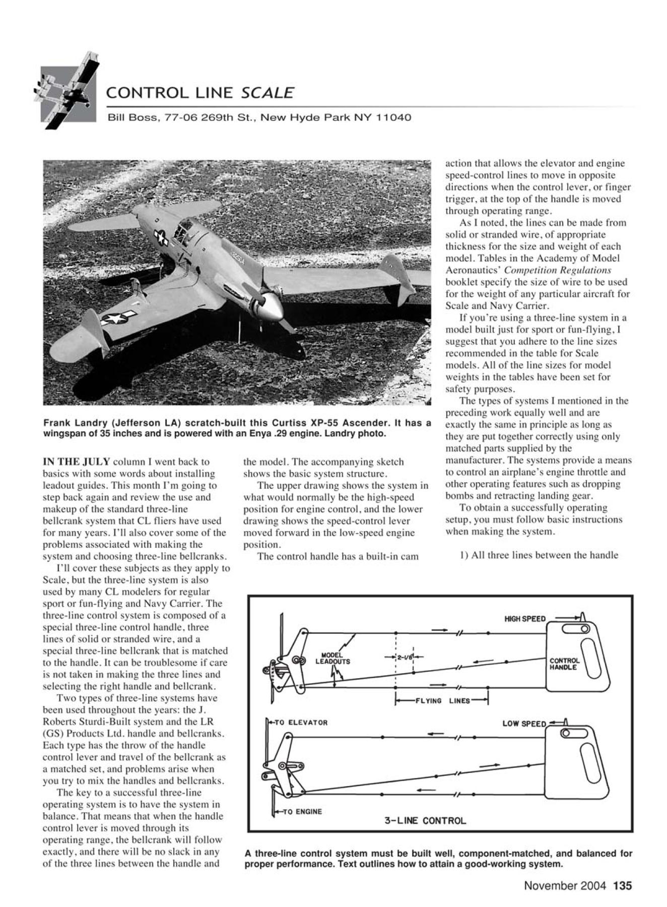
Frank Landry (Jefferson LA) scratch-built this Curtiss XP-55 Ascender. It has a
wingspan of 35 inches and is powered with an Enya .29 engine. Landry photo.
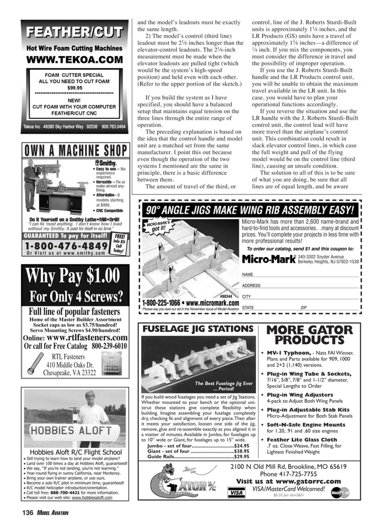
A three-line control system must be built well, component-matched, and balanced for
proper performance. Text outlines how to attain a good-working system.
the model. The accompanying sketch
shows the basic system structure.
The upper drawing shows the system in
what would normally be the high-speed
position for engine control, and the lower
drawing shows the speed-control lever
moved forward in the low-speed engine
position.
The control handle has a built-in cam
action that allows the elevator and engine
speed-control lines to move in opposite
directions when the control lever, or finger
trigger, at the top of the handle is moved
through operating range.
As I noted, the lines can be made from
solid or stranded wire, of appropriate
thickness for the size and weight of each
model. Tables in the Academy of Model
Aeronautics’ Competition Regulations
booklet specify the size of wire to be used
for the weight of any particular aircraft for
Scale and Navy Carrier.
If you’re using a three-line system in a
model built just for sport or fun-flying, I
suggest that you adhere to the line sizes
recommended in the table for Scale
models. All of the line sizes for model
weights in the tables have been set for
safety purposes.
The types of systems I mentioned in the
preceding work equally well and are
exactly the same in principle as long as
they are put together correctly using only
matched parts supplied by the
manufacturer. The systems provide a means
to control an airplane’s engine throttle and
other operating features such as dropping
bombs and retracting landing gear.
To obtain a successfully operating
setup, you must follow basic instructions
when making the system.
1) All three lines between the handle
11sig5.QXD 8/23/04 11:19 am Page 135
136 MODEL AVIATION
and the model’s leadouts must be exactly
the same length.
2) The model’s control (third line)
leadout must be 21⁄8 inches longer than the
elevator-control leadouts. The 21⁄8-inch
measurement must be made when the
elevator leadouts are pulled tight (which
would be the system’s high-speed
position) and held even with each other.
(Refer to the upper portion of the sketch.)
If you build the system as I have
specified, you should have a balanced
setup that maintains equal tension on the
three lines through the entire range of
operation.
The preceding explanation is based on
the idea that the control handle and model
unit are a matched set from the same
manufacturer. I point this out because
even though the operation of the two
systems I mentioned are the same in
principle, there is a basic difference
between them.
The amount of travel of the third, or
control, line of the J. Roberts Sturdi-Built
units is approximately 11⁄8 inches, and the
LR Products (GS) units have a travel of
approximately 13⁄8 inches—a difference of
1⁄4 inch. If you mix the components, you
must consider the difference in travel and
the possibility of improper operation.
If you use the J. Roberts Sturdi-Built
handle and the LR Products control unit,
you will be unable to obtain the maximum
travel available in the LR unit. In this
case, you would have to plan your
operational functions accordingly.
If you reverse the situation and use the
LR handle with the J. Roberts Sturdi-Built
control unit, the control lead will have
more travel than the airplane’s control
unit. This combination could result in
slack elevator control lines, in which case
the full weight and pull of the flying
model would be on the control line (third
line), causing an unsafe condition.
The solution to all of this is to be sure
of what you are doing, be sure that all
lines are of equal length, and be aware
Micro-Mark has more than 2,600 name-brand and
hard-to-find tools and accessories…many at discount
prices. You’ll complete your projects in less time with
more professional results!
340-3302 Snyder Avenue
Berkeley Heights, NJ 07922-1538
NAME
ADDRESS
CITY
STATE ZIP
To order our catalog, send $1 and this coupon to:
1-800-225-1066 • www.micromark.com
®
Please say you saw our ad in the November issue of Model Aviation.
MICRO-MARK’S
got it !
90° ANGLE JIGS MAKE WING RIB ASSEMBLY EASY!
#80344
FUSELAGE JIG STATIONS MORE GATOR
PRODUCTS
If you build wood fuselages you need a set of Jig Stations.
Whether mounted to your bench or the optional unistrut
these stations give complete flexibility when
building. Imagine assembling your fuselage completely
dry, checking fit and alignment of every piece.Then after
it meets your satisfaction, loosen one side of the jig,
remove, glue and re-assemble exactly as you aligned it in
a matter of minutes.Available in Jumbo, for fuselages up
to 10” wide or Giant, for fuselages up to 15” wide.
Jumbo - set of four...............................$24.95
Giant - set of four ................................$38.95
Guide Rails............................................$29.95
The Best Fuselage Jig Ever
... Period!
• MV-1 Typhoon, - Nats FAI Winner,
Plans and Parts available for 909, 1000
and 2+2 (1,140) versions.
• Plug-in Wing Tube & Sockets,
7/16”, 5/8”, 7/8” and 1-1/2” diameter,
Special Lengths to Order
• Plug-in Wing Adjusters
4-pack to Adjust Both Wing Panels
• Plug-in Adjustable Stab Kits
Micro-Adjustment for Both Stab Panels
• Soft-N-Safe Engine Mounts
for 1.20, .91 and .60 size engines
• Feather Lite Glass Cloth
.7 oz. Close Weave, Fast Filling, for
Lightest Finished Weight
2100 N Old Mill Rd, Brookline, MO 65619
Phone 417-725-7755
Visit us at www.gatorrc.com
VISA/MasterCard Welcomed!
$6.50 per itemS&H
OWN A MACHINE SHOP
1-800-476-4849
O r V i s i t u s a t w w w.smithy.com
GUARANTEED To pay for itself! FREE!
Info Kit
FREE!
Info Kit
Call
Today!
“I can fix ‘most anything. I don’t know how I lived
without my Smithy. It paid for itself in no time.”
• Easy to use – No
experience
required.
• Versatile – Fix or
make almost anything.
• Affordalbe-- 6
models starting
at $995.
• CNC Compatible
Do It Yourself on a Smithy Lathe•Mill•Drill!
11sig5.QXD 8/23/04 11:20 am Page 136
that if you mix components, adjustments
have to be made.
Now that I have discussed the two
systems that have been, or may still be, in
use, I have found that only one system is
now available: Brodak Manufacturing’s.
Talking with John Brodak, I learned that
the original J. Roberts Sturdi-Built units
(which were distributed in the early
1980s) and the LR Products handle and
bellcrank units are incompatible. The LR
Products units were much improved in
sturdiness, and, as I noted, had more
travel in the third line operation.
As far as I can determine, Brodak is
the only manufacturer of the three-line
handles and bellcranks. It offers the
heavy-duty Brodak-J. Roberts three-line
bellcrank system. The company is also
offering heavy-duty handles and an
assortment of short- and long-span
upright and inverted bellcranks. They
come in 21⁄2- and 31⁄2-inch spans for
elevator-line connections. The short span
allows for quicker elevator movement and
the longer span provides for slower
elevator action for those slow, rise-offground
takeoffs and precise flight
maneuvers.
Whether you use the inverted or the
upright unit will depend on the kind of
model you have, such as sport or
Precision Scale, and where it is mounted
in the fuselage or wing. If you employ the
Brodak three-line system, you can be sure
that you will be using a matched set of
controls that provide full functionality
and smooth operation.
For further details about the three-line
bellcrank and all the other CL products
that Brodak sells, please contact Brodak
Manufacturing at 100 Park Ave.,
Carmichaels PA 15320, call (724) 966-
2726, or visit the Web site at www.brod
ak.com.
The Curtiss XP-55 Ascender (pusher)
shown is the work of Frank Landry of
Jefferson, Louisiana. He scratch-built the
model from enlarged FF plans to
dimensions that would accommodate 25-
to 35-size engines. The XP-55 has an
Enya .29 for power and is throttlecontrolled
with a standard three-line
system. It looks large in the photo but
spans only 35 inches.
Although it looks fairly good from a
detail standpoint, Frank noted that the
Ascender does not fly well. Too much
nose weight (16 ounces) was needed
because the CG was so far back.
I couldn’t find anything in my aviation
library about the XP-55, but I suspect
that, as were most of its type of
experimental aircraft, the prototype was
also a poor performer.
Please send ideas, notice of upcoming CL
Scale events, contest reports, and especially
photos of CL Scale activity to me at the
address at the top of this column. MA
138 MODEL AVIATION
WW1 AERO 1900 to 1919 SKYWAYS 1920 to 1940
✪ early technical books, magazines
✪ copies of original drawings, manuals
✪ assistance in locating parts, information
✪ back issues of the 2 Journals
✪ donated copies of early aviation books
✪ a worldwide networking service
SERVICES WE PROVIDE
SAMPLE ISSUES @$4 + $3 postage
FREE BACK ISSUE FOR NEW SUBSCRIBERS: MENTION THIS AD!
15 Crescent Road • Poughkeepsie, NY 12601 USA • 845-473-3679
Valuable
Resources
for the Scale
and
Full Scale
Builder
OUR TWO JOURNALS
✪ information on current projects
✪ news of museums and air shows
✪ technical drawings and data
✪ aeroplanes, engines, parts for sale
✪ scale modelling material
✪ your wants and disposals
✪ news of current publications
✪ information on paint and color
✪ photographs
✪ historical research
✪ workshop notes
ESTATE LIQUIDATION SERVICES
For information, call 281-998-2529, or send SASE to:
GCBM R/C Models Inc.
PO Box 7967, Pasadena, TX 77508 • website: gcbmrc.com
• We buy: R/C Airplane Kits, ARF’s,
Engines, Radios, Field Equipment,
Building Accessories
• Entire Estates
• Vintage and Antique Collections
• Hobby Shop Inventories
• New or Used
• Pick-up Service Available
AMA Academy of Model
Aeronautics
ARF Almost Ready to Fly
BEC Battery Eliminator Circuit
CAD computer-aided design
cc cubic centimeter
CD contest director or
compact disc
CG center of gravity
CL Control Line
cm centimeter
cu. in. cubic inch
DT dethermalizer
EPP (foam) expanded polypropylene
ESC Electronic Speed Control
FAI Fédération Aéronautique
Internationale
FCC Federal Communications
Commission
FF Free Flight
LCD Liquid Crystal Display
LE leading edge
LED light-emitting diode
Li-Poly Lithium Polymer
mA milliamperes
MA Model Aviation
mAh milliampere-hours
MHz megahertz
mm millimeter
Nats AMA Nationals
Ni-Cd Nickel Cadmium
NiMH Nickel Metal Hydride
RC Radio Control
rpm revolutions per minute
RTF Ready to Fly
SASE self-addressed, stamped
envelope
SIG Special Interest Group
TE trailing edge
ModelAviation’s
Frequently Used Abbreviations/Acronyms
11sig5.QXD 8/23/04 11:20 am Page 138
Edition: Model Aviation - 2004/11
Page Numbers: 135,136,138
Edition: Model Aviation - 2004/11
Page Numbers: 135,136,138
November 2004 135
CONTROL LINE SCALE
Bill Boss, 77-06 269th St., New Hyde Park NY 11040
IN THE JULY column I went back to
basics with some words about installing
leadout guides. This month I’m going to
step back again and review the use and
makeup of the standard three-line
bellcrank system that CL fliers have used
for many years. I’ll also cover some of the
problems associated with making the
system and choosing three-line bellcranks.
I’ll cover these subjects as they apply to
Scale, but the three-line system is also
used by many CL modelers for regular
sport or fun-flying and Navy Carrier. The
three-line control system is composed of a
special three-line control handle, three
lines of solid or stranded wire, and a
special three-line bellcrank that is matched
to the handle. It can be troublesome if care
is not taken in making the three lines and
selecting the right handle and bellcrank.
Two types of three-line systems have
been used throughout the years: the J.
Roberts Sturdi-Built system and the LR
(GS) Products Ltd. handle and bellcranks.
Each type has the throw of the handle
control lever and travel of the bellcrank as
a matched set, and problems arise when
you try to mix the handles and bellcranks.
The key to a successful three-line
operating system is to have the system in
balance. That means that when the handle
control lever is moved through its
operating range, the bellcrank will follow
exactly, and there will be no slack in any
of the three lines between the handle and
Frank Landry (Jefferson LA) scratch-built this Curtiss XP-55 Ascender. It has a
wingspan of 35 inches and is powered with an Enya .29 engine. Landry photo.
A three-line control system must be built well, component-matched, and balanced for
proper performance. Text outlines how to attain a good-working system.
the model. The accompanying sketch
shows the basic system structure.
The upper drawing shows the system in
what would normally be the high-speed
position for engine control, and the lower
drawing shows the speed-control lever
moved forward in the low-speed engine
position.
The control handle has a built-in cam
action that allows the elevator and engine
speed-control lines to move in opposite
directions when the control lever, or finger
trigger, at the top of the handle is moved
through operating range.
As I noted, the lines can be made from
solid or stranded wire, of appropriate
thickness for the size and weight of each
model. Tables in the Academy of Model
Aeronautics’ Competition Regulations
booklet specify the size of wire to be used
for the weight of any particular aircraft for
Scale and Navy Carrier.
If you’re using a three-line system in a
model built just for sport or fun-flying, I
suggest that you adhere to the line sizes
recommended in the table for Scale
models. All of the line sizes for model
weights in the tables have been set for
safety purposes.
The types of systems I mentioned in the
preceding work equally well and are
exactly the same in principle as long as
they are put together correctly using only
matched parts supplied by the
manufacturer. The systems provide a means
to control an airplane’s engine throttle and
other operating features such as dropping
bombs and retracting landing gear.
To obtain a successfully operating
setup, you must follow basic instructions
when making the system.
1) All three lines between the handle
11sig5.QXD 8/23/04 11:19 am Page 135
136 MODEL AVIATION
and the model’s leadouts must be exactly
the same length.
2) The model’s control (third line)
leadout must be 21⁄8 inches longer than the
elevator-control leadouts. The 21⁄8-inch
measurement must be made when the
elevator leadouts are pulled tight (which
would be the system’s high-speed
position) and held even with each other.
(Refer to the upper portion of the sketch.)
If you build the system as I have
specified, you should have a balanced
setup that maintains equal tension on the
three lines through the entire range of
operation.
The preceding explanation is based on
the idea that the control handle and model
unit are a matched set from the same
manufacturer. I point this out because
even though the operation of the two
systems I mentioned are the same in
principle, there is a basic difference
between them.
The amount of travel of the third, or
control, line of the J. Roberts Sturdi-Built
units is approximately 11⁄8 inches, and the
LR Products (GS) units have a travel of
approximately 13⁄8 inches—a difference of
1⁄4 inch. If you mix the components, you
must consider the difference in travel and
the possibility of improper operation.
If you use the J. Roberts Sturdi-Built
handle and the LR Products control unit,
you will be unable to obtain the maximum
travel available in the LR unit. In this
case, you would have to plan your
operational functions accordingly.
If you reverse the situation and use the
LR handle with the J. Roberts Sturdi-Built
control unit, the control lead will have
more travel than the airplane’s control
unit. This combination could result in
slack elevator control lines, in which case
the full weight and pull of the flying
model would be on the control line (third
line), causing an unsafe condition.
The solution to all of this is to be sure
of what you are doing, be sure that all
lines are of equal length, and be aware
Micro-Mark has more than 2,600 name-brand and
hard-to-find tools and accessories…many at discount
prices. You’ll complete your projects in less time with
more professional results!
340-3302 Snyder Avenue
Berkeley Heights, NJ 07922-1538
NAME
ADDRESS
CITY
STATE ZIP
To order our catalog, send $1 and this coupon to:
1-800-225-1066 • www.micromark.com
®
Please say you saw our ad in the November issue of Model Aviation.
MICRO-MARK’S
got it !
90° ANGLE JIGS MAKE WING RIB ASSEMBLY EASY!
#80344
FUSELAGE JIG STATIONS MORE GATOR
PRODUCTS
If you build wood fuselages you need a set of Jig Stations.
Whether mounted to your bench or the optional unistrut
these stations give complete flexibility when
building. Imagine assembling your fuselage completely
dry, checking fit and alignment of every piece.Then after
it meets your satisfaction, loosen one side of the jig,
remove, glue and re-assemble exactly as you aligned it in
a matter of minutes.Available in Jumbo, for fuselages up
to 10” wide or Giant, for fuselages up to 15” wide.
Jumbo - set of four...............................$24.95
Giant - set of four ................................$38.95
Guide Rails............................................$29.95
The Best Fuselage Jig Ever
... Period!
• MV-1 Typhoon, - Nats FAI Winner,
Plans and Parts available for 909, 1000
and 2+2 (1,140) versions.
• Plug-in Wing Tube & Sockets,
7/16”, 5/8”, 7/8” and 1-1/2” diameter,
Special Lengths to Order
• Plug-in Wing Adjusters
4-pack to Adjust Both Wing Panels
• Plug-in Adjustable Stab Kits
Micro-Adjustment for Both Stab Panels
• Soft-N-Safe Engine Mounts
for 1.20, .91 and .60 size engines
• Feather Lite Glass Cloth
.7 oz. Close Weave, Fast Filling, for
Lightest Finished Weight
2100 N Old Mill Rd, Brookline, MO 65619
Phone 417-725-7755
Visit us at www.gatorrc.com
VISA/MasterCard Welcomed!
$6.50 per itemS&H
OWN A MACHINE SHOP
1-800-476-4849
O r V i s i t u s a t w w w.smithy.com
GUARANTEED To pay for itself! FREE!
Info Kit
FREE!
Info Kit
Call
Today!
“I can fix ‘most anything. I don’t know how I lived
without my Smithy. It paid for itself in no time.”
• Easy to use – No
experience
required.
• Versatile – Fix or
make almost anything.
• Affordalbe-- 6
models starting
at $995.
• CNC Compatible
Do It Yourself on a Smithy Lathe•Mill•Drill!
11sig5.QXD 8/23/04 11:20 am Page 136
that if you mix components, adjustments
have to be made.
Now that I have discussed the two
systems that have been, or may still be, in
use, I have found that only one system is
now available: Brodak Manufacturing’s.
Talking with John Brodak, I learned that
the original J. Roberts Sturdi-Built units
(which were distributed in the early
1980s) and the LR Products handle and
bellcrank units are incompatible. The LR
Products units were much improved in
sturdiness, and, as I noted, had more
travel in the third line operation.
As far as I can determine, Brodak is
the only manufacturer of the three-line
handles and bellcranks. It offers the
heavy-duty Brodak-J. Roberts three-line
bellcrank system. The company is also
offering heavy-duty handles and an
assortment of short- and long-span
upright and inverted bellcranks. They
come in 21⁄2- and 31⁄2-inch spans for
elevator-line connections. The short span
allows for quicker elevator movement and
the longer span provides for slower
elevator action for those slow, rise-offground
takeoffs and precise flight
maneuvers.
Whether you use the inverted or the
upright unit will depend on the kind of
model you have, such as sport or
Precision Scale, and where it is mounted
in the fuselage or wing. If you employ the
Brodak three-line system, you can be sure
that you will be using a matched set of
controls that provide full functionality
and smooth operation.
For further details about the three-line
bellcrank and all the other CL products
that Brodak sells, please contact Brodak
Manufacturing at 100 Park Ave.,
Carmichaels PA 15320, call (724) 966-
2726, or visit the Web site at www.brod
ak.com.
The Curtiss XP-55 Ascender (pusher)
shown is the work of Frank Landry of
Jefferson, Louisiana. He scratch-built the
model from enlarged FF plans to
dimensions that would accommodate 25-
to 35-size engines. The XP-55 has an
Enya .29 for power and is throttlecontrolled
with a standard three-line
system. It looks large in the photo but
spans only 35 inches.
Although it looks fairly good from a
detail standpoint, Frank noted that the
Ascender does not fly well. Too much
nose weight (16 ounces) was needed
because the CG was so far back.
I couldn’t find anything in my aviation
library about the XP-55, but I suspect
that, as were most of its type of
experimental aircraft, the prototype was
also a poor performer.
Please send ideas, notice of upcoming CL
Scale events, contest reports, and especially
photos of CL Scale activity to me at the
address at the top of this column. MA
138 MODEL AVIATION
WW1 AERO 1900 to 1919 SKYWAYS 1920 to 1940
✪ early technical books, magazines
✪ copies of original drawings, manuals
✪ assistance in locating parts, information
✪ back issues of the 2 Journals
✪ donated copies of early aviation books
✪ a worldwide networking service
SERVICES WE PROVIDE
SAMPLE ISSUES @$4 + $3 postage
FREE BACK ISSUE FOR NEW SUBSCRIBERS: MENTION THIS AD!
15 Crescent Road • Poughkeepsie, NY 12601 USA • 845-473-3679
Valuable
Resources
for the Scale
and
Full Scale
Builder
OUR TWO JOURNALS
✪ information on current projects
✪ news of museums and air shows
✪ technical drawings and data
✪ aeroplanes, engines, parts for sale
✪ scale modelling material
✪ your wants and disposals
✪ news of current publications
✪ information on paint and color
✪ photographs
✪ historical research
✪ workshop notes
ESTATE LIQUIDATION SERVICES
For information, call 281-998-2529, or send SASE to:
GCBM R/C Models Inc.
PO Box 7967, Pasadena, TX 77508 • website: gcbmrc.com
• We buy: R/C Airplane Kits, ARF’s,
Engines, Radios, Field Equipment,
Building Accessories
• Entire Estates
• Vintage and Antique Collections
• Hobby Shop Inventories
• New or Used
• Pick-up Service Available
AMA Academy of Model
Aeronautics
ARF Almost Ready to Fly
BEC Battery Eliminator Circuit
CAD computer-aided design
cc cubic centimeter
CD contest director or
compact disc
CG center of gravity
CL Control Line
cm centimeter
cu. in. cubic inch
DT dethermalizer
EPP (foam) expanded polypropylene
ESC Electronic Speed Control
FAI Fédération Aéronautique
Internationale
FCC Federal Communications
Commission
FF Free Flight
LCD Liquid Crystal Display
LE leading edge
LED light-emitting diode
Li-Poly Lithium Polymer
mA milliamperes
MA Model Aviation
mAh milliampere-hours
MHz megahertz
mm millimeter
Nats AMA Nationals
Ni-Cd Nickel Cadmium
NiMH Nickel Metal Hydride
RC Radio Control
rpm revolutions per minute
RTF Ready to Fly
SASE self-addressed, stamped
envelope
SIG Special Interest Group
TE trailing edge
ModelAviation’s
Frequently Used Abbreviations/Acronyms
11sig5.QXD 8/23/04 11:20 am Page 138
Edition: Model Aviation - 2004/11
Page Numbers: 135,136,138
November 2004 135
CONTROL LINE SCALE
Bill Boss, 77-06 269th St., New Hyde Park NY 11040
IN THE JULY column I went back to
basics with some words about installing
leadout guides. This month I’m going to
step back again and review the use and
makeup of the standard three-line
bellcrank system that CL fliers have used
for many years. I’ll also cover some of the
problems associated with making the
system and choosing three-line bellcranks.
I’ll cover these subjects as they apply to
Scale, but the three-line system is also
used by many CL modelers for regular
sport or fun-flying and Navy Carrier. The
three-line control system is composed of a
special three-line control handle, three
lines of solid or stranded wire, and a
special three-line bellcrank that is matched
to the handle. It can be troublesome if care
is not taken in making the three lines and
selecting the right handle and bellcrank.
Two types of three-line systems have
been used throughout the years: the J.
Roberts Sturdi-Built system and the LR
(GS) Products Ltd. handle and bellcranks.
Each type has the throw of the handle
control lever and travel of the bellcrank as
a matched set, and problems arise when
you try to mix the handles and bellcranks.
The key to a successful three-line
operating system is to have the system in
balance. That means that when the handle
control lever is moved through its
operating range, the bellcrank will follow
exactly, and there will be no slack in any
of the three lines between the handle and
Frank Landry (Jefferson LA) scratch-built this Curtiss XP-55 Ascender. It has a
wingspan of 35 inches and is powered with an Enya .29 engine. Landry photo.
A three-line control system must be built well, component-matched, and balanced for
proper performance. Text outlines how to attain a good-working system.
the model. The accompanying sketch
shows the basic system structure.
The upper drawing shows the system in
what would normally be the high-speed
position for engine control, and the lower
drawing shows the speed-control lever
moved forward in the low-speed engine
position.
The control handle has a built-in cam
action that allows the elevator and engine
speed-control lines to move in opposite
directions when the control lever, or finger
trigger, at the top of the handle is moved
through operating range.
As I noted, the lines can be made from
solid or stranded wire, of appropriate
thickness for the size and weight of each
model. Tables in the Academy of Model
Aeronautics’ Competition Regulations
booklet specify the size of wire to be used
for the weight of any particular aircraft for
Scale and Navy Carrier.
If you’re using a three-line system in a
model built just for sport or fun-flying, I
suggest that you adhere to the line sizes
recommended in the table for Scale
models. All of the line sizes for model
weights in the tables have been set for
safety purposes.
The types of systems I mentioned in the
preceding work equally well and are
exactly the same in principle as long as
they are put together correctly using only
matched parts supplied by the
manufacturer. The systems provide a means
to control an airplane’s engine throttle and
other operating features such as dropping
bombs and retracting landing gear.
To obtain a successfully operating
setup, you must follow basic instructions
when making the system.
1) All three lines between the handle
11sig5.QXD 8/23/04 11:19 am Page 135
136 MODEL AVIATION
and the model’s leadouts must be exactly
the same length.
2) The model’s control (third line)
leadout must be 21⁄8 inches longer than the
elevator-control leadouts. The 21⁄8-inch
measurement must be made when the
elevator leadouts are pulled tight (which
would be the system’s high-speed
position) and held even with each other.
(Refer to the upper portion of the sketch.)
If you build the system as I have
specified, you should have a balanced
setup that maintains equal tension on the
three lines through the entire range of
operation.
The preceding explanation is based on
the idea that the control handle and model
unit are a matched set from the same
manufacturer. I point this out because
even though the operation of the two
systems I mentioned are the same in
principle, there is a basic difference
between them.
The amount of travel of the third, or
control, line of the J. Roberts Sturdi-Built
units is approximately 11⁄8 inches, and the
LR Products (GS) units have a travel of
approximately 13⁄8 inches—a difference of
1⁄4 inch. If you mix the components, you
must consider the difference in travel and
the possibility of improper operation.
If you use the J. Roberts Sturdi-Built
handle and the LR Products control unit,
you will be unable to obtain the maximum
travel available in the LR unit. In this
case, you would have to plan your
operational functions accordingly.
If you reverse the situation and use the
LR handle with the J. Roberts Sturdi-Built
control unit, the control lead will have
more travel than the airplane’s control
unit. This combination could result in
slack elevator control lines, in which case
the full weight and pull of the flying
model would be on the control line (third
line), causing an unsafe condition.
The solution to all of this is to be sure
of what you are doing, be sure that all
lines are of equal length, and be aware
Micro-Mark has more than 2,600 name-brand and
hard-to-find tools and accessories…many at discount
prices. You’ll complete your projects in less time with
more professional results!
340-3302 Snyder Avenue
Berkeley Heights, NJ 07922-1538
NAME
ADDRESS
CITY
STATE ZIP
To order our catalog, send $1 and this coupon to:
1-800-225-1066 • www.micromark.com
®
Please say you saw our ad in the November issue of Model Aviation.
MICRO-MARK’S
got it !
90° ANGLE JIGS MAKE WING RIB ASSEMBLY EASY!
#80344
FUSELAGE JIG STATIONS MORE GATOR
PRODUCTS
If you build wood fuselages you need a set of Jig Stations.
Whether mounted to your bench or the optional unistrut
these stations give complete flexibility when
building. Imagine assembling your fuselage completely
dry, checking fit and alignment of every piece.Then after
it meets your satisfaction, loosen one side of the jig,
remove, glue and re-assemble exactly as you aligned it in
a matter of minutes.Available in Jumbo, for fuselages up
to 10” wide or Giant, for fuselages up to 15” wide.
Jumbo - set of four...............................$24.95
Giant - set of four ................................$38.95
Guide Rails............................................$29.95
The Best Fuselage Jig Ever
... Period!
• MV-1 Typhoon, - Nats FAI Winner,
Plans and Parts available for 909, 1000
and 2+2 (1,140) versions.
• Plug-in Wing Tube & Sockets,
7/16”, 5/8”, 7/8” and 1-1/2” diameter,
Special Lengths to Order
• Plug-in Wing Adjusters
4-pack to Adjust Both Wing Panels
• Plug-in Adjustable Stab Kits
Micro-Adjustment for Both Stab Panels
• Soft-N-Safe Engine Mounts
for 1.20, .91 and .60 size engines
• Feather Lite Glass Cloth
.7 oz. Close Weave, Fast Filling, for
Lightest Finished Weight
2100 N Old Mill Rd, Brookline, MO 65619
Phone 417-725-7755
Visit us at www.gatorrc.com
VISA/MasterCard Welcomed!
$6.50 per itemS&H
OWN A MACHINE SHOP
1-800-476-4849
O r V i s i t u s a t w w w.smithy.com
GUARANTEED To pay for itself! FREE!
Info Kit
FREE!
Info Kit
Call
Today!
“I can fix ‘most anything. I don’t know how I lived
without my Smithy. It paid for itself in no time.”
• Easy to use – No
experience
required.
• Versatile – Fix or
make almost anything.
• Affordalbe-- 6
models starting
at $995.
• CNC Compatible
Do It Yourself on a Smithy Lathe•Mill•Drill!
11sig5.QXD 8/23/04 11:20 am Page 136
that if you mix components, adjustments
have to be made.
Now that I have discussed the two
systems that have been, or may still be, in
use, I have found that only one system is
now available: Brodak Manufacturing’s.
Talking with John Brodak, I learned that
the original J. Roberts Sturdi-Built units
(which were distributed in the early
1980s) and the LR Products handle and
bellcrank units are incompatible. The LR
Products units were much improved in
sturdiness, and, as I noted, had more
travel in the third line operation.
As far as I can determine, Brodak is
the only manufacturer of the three-line
handles and bellcranks. It offers the
heavy-duty Brodak-J. Roberts three-line
bellcrank system. The company is also
offering heavy-duty handles and an
assortment of short- and long-span
upright and inverted bellcranks. They
come in 21⁄2- and 31⁄2-inch spans for
elevator-line connections. The short span
allows for quicker elevator movement and
the longer span provides for slower
elevator action for those slow, rise-offground
takeoffs and precise flight
maneuvers.
Whether you use the inverted or the
upright unit will depend on the kind of
model you have, such as sport or
Precision Scale, and where it is mounted
in the fuselage or wing. If you employ the
Brodak three-line system, you can be sure
that you will be using a matched set of
controls that provide full functionality
and smooth operation.
For further details about the three-line
bellcrank and all the other CL products
that Brodak sells, please contact Brodak
Manufacturing at 100 Park Ave.,
Carmichaels PA 15320, call (724) 966-
2726, or visit the Web site at www.brod
ak.com.
The Curtiss XP-55 Ascender (pusher)
shown is the work of Frank Landry of
Jefferson, Louisiana. He scratch-built the
model from enlarged FF plans to
dimensions that would accommodate 25-
to 35-size engines. The XP-55 has an
Enya .29 for power and is throttlecontrolled
with a standard three-line
system. It looks large in the photo but
spans only 35 inches.
Although it looks fairly good from a
detail standpoint, Frank noted that the
Ascender does not fly well. Too much
nose weight (16 ounces) was needed
because the CG was so far back.
I couldn’t find anything in my aviation
library about the XP-55, but I suspect
that, as were most of its type of
experimental aircraft, the prototype was
also a poor performer.
Please send ideas, notice of upcoming CL
Scale events, contest reports, and especially
photos of CL Scale activity to me at the
address at the top of this column. MA
138 MODEL AVIATION
WW1 AERO 1900 to 1919 SKYWAYS 1920 to 1940
✪ early technical books, magazines
✪ copies of original drawings, manuals
✪ assistance in locating parts, information
✪ back issues of the 2 Journals
✪ donated copies of early aviation books
✪ a worldwide networking service
SERVICES WE PROVIDE
SAMPLE ISSUES @$4 + $3 postage
FREE BACK ISSUE FOR NEW SUBSCRIBERS: MENTION THIS AD!
15 Crescent Road • Poughkeepsie, NY 12601 USA • 845-473-3679
Valuable
Resources
for the Scale
and
Full Scale
Builder
OUR TWO JOURNALS
✪ information on current projects
✪ news of museums and air shows
✪ technical drawings and data
✪ aeroplanes, engines, parts for sale
✪ scale modelling material
✪ your wants and disposals
✪ news of current publications
✪ information on paint and color
✪ photographs
✪ historical research
✪ workshop notes
ESTATE LIQUIDATION SERVICES
For information, call 281-998-2529, or send SASE to:
GCBM R/C Models Inc.
PO Box 7967, Pasadena, TX 77508 • website: gcbmrc.com
• We buy: R/C Airplane Kits, ARF’s,
Engines, Radios, Field Equipment,
Building Accessories
• Entire Estates
• Vintage and Antique Collections
• Hobby Shop Inventories
• New or Used
• Pick-up Service Available
AMA Academy of Model
Aeronautics
ARF Almost Ready to Fly
BEC Battery Eliminator Circuit
CAD computer-aided design
cc cubic centimeter
CD contest director or
compact disc
CG center of gravity
CL Control Line
cm centimeter
cu. in. cubic inch
DT dethermalizer
EPP (foam) expanded polypropylene
ESC Electronic Speed Control
FAI Fédération Aéronautique
Internationale
FCC Federal Communications
Commission
FF Free Flight
LCD Liquid Crystal Display
LE leading edge
LED light-emitting diode
Li-Poly Lithium Polymer
mA milliamperes
MA Model Aviation
mAh milliampere-hours
MHz megahertz
mm millimeter
Nats AMA Nationals
Ni-Cd Nickel Cadmium
NiMH Nickel Metal Hydride
RC Radio Control
rpm revolutions per minute
RTF Ready to Fly
SASE self-addressed, stamped
envelope
SIG Special Interest Group
TE trailing edge
ModelAviation’s
Frequently Used Abbreviations/Acronyms
11sig5.QXD 8/23/04 11:20 am Page 138

