
88 MODEL AVIATION
Joe Wagner
T h e E n g i n e S h o p
212 S. Pine Ave., Ozark AL 36360
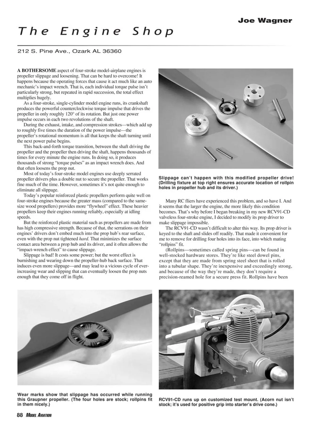
Slippage can’t happen with this modified propeller drive!
(Drilling fixture at top right ensures accurate location of rollpin
holes in propeller hub and its driver.)
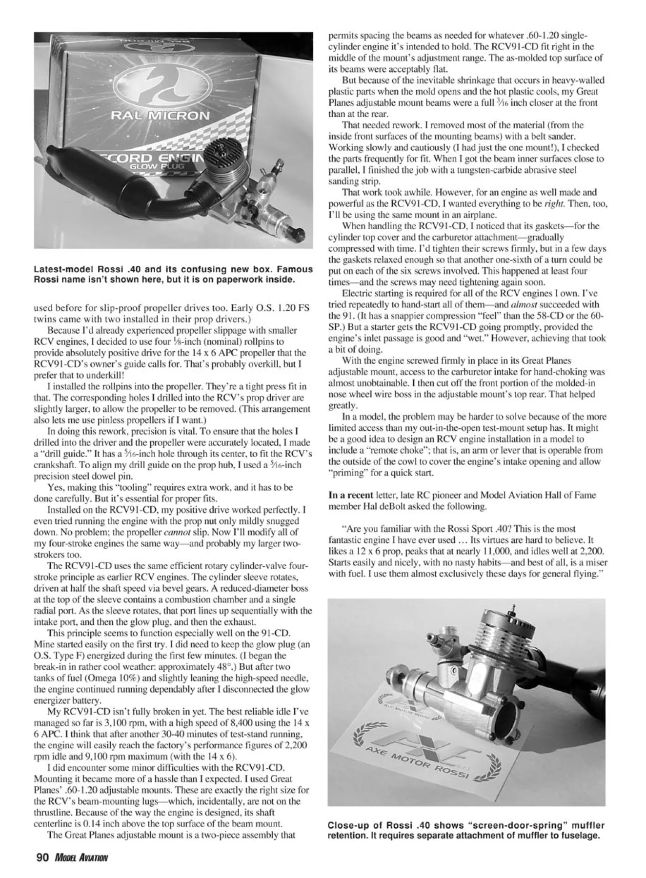
RCV91-CD runs up on customized test mount. (Acorn nut isn’t
stock; it’s used for positive grip into starter’s drive cone.)
Wear marks show that slippage has occurred while running
this Graupner propeller. (The four holes are stock; rollpins fit
in them nicely.)
A BOTHERSOME aspect of four-stroke model-airplane engines is
propeller slippage and loosening. That can be hard to overcome! It
happens because the operating forces that cause it act much like an auto
mechanic’s impact wrench. That is, each individual torque pulse isn’t
particularly strong, but repeated in rapid succession, the total effect
multiplies hugely.
As a four-stroke, single-cylinder model engine runs, its crankshaft
produces the powerful counterclockwise torque impulse that drives the
propeller in only roughly 120° of its rotation. But just one power
impulse occurs in each two revolutions of the shaft.
During the exhaust, intake, and compression strokes—which add up
to roughly five times the duration of the power impulse—the
propeller’s rotational momentum is all that keeps the shaft turning until
the next power pulse begins.
This back-and-forth torque transition, between the shaft driving the
propeller and the propeller then driving the shaft, happens thousands of
times for every minute the engine runs. In doing so, it produces
thousands of strong “torque pulses” as an impact wrench does. And
that often loosens the prop nut.
Most of today’s four-stroke model engines use deeply serrated
propeller drivers plus a double nut to secure the propeller. That works
fine much of the time. However, sometimes it’s not quite enough to
eliminate all slippage.
Today’s popular reinforced plastic propellers perform quite well on
four-stroke engines because the greater mass (compared to the samesize
wood propellers) provides more “flywheel” effect. These heavier
propellers keep their engines running reliably, especially at idling
speeds.
But the reinforced plastic material such as propellers are made from
has high compressive strength. Because of that, the serrations on their
engines’ drivers don’t embed much into the prop hub’s rear surface,
even with the prop nut tightened hard. That minimizes the surface
contact area between a prop hub and its driver, and it often allows the
“impact-wrench effect” to cause slippage.
Slippage is bad! It costs some power; but the worst effect is
burnishing and wearing down the propeller-hub back surface. That
induces even more slippage—and may lead to a vicious cycle of everincreasing
wear and slipping that can eventually loosen the prop nuts
enough that they come off in flight.
Many RC fliers have experienced this problem, and so have I. And
it seems that the larger the engine, the more likely this condition
becomes. That’s why before I began breaking in my new RCV91-CD
valveless four-stroke engine, I decided to modify its prop driver to
make slippage impossible.
The RCV91-CD wasn’t difficult to alter this way. Its prop driver is
keyed to the shaft and slides off readily. That made it convenient for
me to remove for drilling four holes into its face, into which mating
“rollpins” fit.
(Rollpins—sometimes called spring pins—can be found in
well-stocked hardware stores. They’re like steel dowel pins,
except that they are made from spring steel sheet that is rolled
into a tubular shape. They’re inexpensive and exceedingly strong,
and because of the way they’re made, they don’t require a
precision-reamed hole for a secure press fit. Rollpins have been
used before for slip-proof propeller drives too. Early O.S. 1.20 FS
twins came with two installed in their prop drivers.)
Because I’d already experienced propeller slippage with smaller
RCV engines, I decided to use four 1⁄8-inch (nominal) rollpins to
provide absolutely positive drive for the 14 x 6 APC propeller that the
RCV91-CD’s owner’s guide calls for. That’s probably overkill, but I
prefer that to underkill!
I installed the rollpins into the propeller. They’re a tight press fit in
that. The corresponding holes I drilled into the RCV’s prop driver are
slightly larger, to allow the propeller to be removed. (This arrangement
also lets me use pinless propellers if I want.)
In doing this rework, precision is vital. To ensure that the holes I
drilled into the driver and the propeller were accurately located, I made
a “drill guide.” It has a 5⁄16-inch hole through its center, to fit the RCV’s
crankshaft. To align my drill guide on the prop hub, I used a 5⁄16-inch
precision steel dowel pin.
Yes, making this “tooling” requires extra work, and it has to be
done carefully. But it’s essential for proper fits.
Installed on the RCV91-CD, my positive drive worked perfectly. I
even tried running the engine with the prop nut only mildly snugged
down. No problem; the propeller cannot slip. Now I’ll modify all of
my four-stroke engines the same way—and probably my larger twostrokers
too.
The RCV91-CD uses the same efficient rotary cylinder-valve fourstroke
principle as earlier RCV engines. The cylinder sleeve rotates,
driven at half the shaft speed via bevel gears. A reduced-diameter boss
at the top of the sleeve contains a combustion chamber and a single
radial port. As the sleeve rotates, that port lines up sequentially with the
intake port, and then the glow plug, and then the exhaust.
This principle seems to function especially well on the 91-CD.
Mine started easily on the first try. I did need to keep the glow plug (an
O.S. Type F) energized during the first few minutes. (I began the
break-in in rather cool weather: approximately 48°.) But after two
tanks of fuel (Omega 10%) and slightly leaning the high-speed needle,
the engine continued running dependably after I disconnected the glow
energizer battery.
My RCV91-CD isn’t fully broken in yet. The best reliable idle I’ve
managed so far is 3,100 rpm, with a high speed of 8,400 using the 14 x
6 APC. I think that after another 30-40 minutes of test-stand running,
the engine will easily reach the factory’s performance figures of 2,200
rpm idle and 9,100 rpm maximum (with the 14 x 6).
I did encounter some minor difficulties with the RCV91-CD.
Mounting it became more of a hassle than I expected. I used Great
Planes’ .60-1.20 adjustable mounts. These are exactly the right size for
the RCV’s beam-mounting lugs—which, incidentally, are not on the
thrustline. Because of the way the engine is designed, its shaft
centerline is 0.14 inch above the top surface of the beam mount.
The Great Planes adjustable mount is a two-piece assembly that
permits spacing the beams as needed for whatever .60-1.20 singlecylinder
engine it’s intended to hold. The RCV91-CD fit right in the
middle of the mount’s adjustment range. The as-molded top surface of
its beams were acceptably flat.
But because of the inevitable shrinkage that occurs in heavy-walled
plastic parts when the mold opens and the hot plastic cools, my Great
Planes adjustable mount beams were a full 3⁄16 inch closer at the front
than at the rear.
That needed rework. I removed most of the material (from the
inside front surfaces of the mounting beams) with a belt sander.
Working slowly and cautiously (I had just the one mount!), I checked
the parts frequently for fit. When I got the beam inner surfaces close to
parallel, I finished the job with a tungsten-carbide abrasive steel
sanding strip.
That work took awhile. However, for an engine as well made and
powerful as the RCV91-CD, I wanted everything to be right. Then, too,
I’ll be using the same mount in an airplane.
When handling the RCV91-CD, I noticed that its gaskets—for the
cylinder top cover and the carburetor attachment—gradually
compressed with time. I’d tighten their screws firmly, but in a few days
the gaskets relaxed enough so that another one-sixth of a turn could be
put on each of the six screws involved. This happened at least four
times—and the screws may need tightening again soon.
Electric starting is required for all of the RCV engines I own. I’ve
tried repeatedly to hand-start all of them—and almost succeeded with
the 91. (It has a snappier compression “feel” than the 58-CD or the 60-
SP.) But a starter gets the RCV91-CD going promptly, provided the
engine’s inlet passage is good and “wet.” However, achieving that took
a bit of doing.
With the engine screwed firmly in place in its Great Planes
adjustable mount, access to the carburetor intake for hand-choking was
almost unobtainable. I then cut off the front portion of the molded-in
nose wheel wire boss in the adjustable mount’s top rear. That helped
greatly.
In a model, the problem may be harder to solve because of the more
limited access than my out-in-the-open test-mount setup has. It might
be a good idea to design an RCV engine installation in a model to
include a “remote choke”; that is, an arm or lever that is operable from
the outside of the cowl to cover the engine’s intake opening and allow
“priming” for a quick start.
In a recent letter, late RC pioneer and Model Aviation Hall of Fame
member Hal deBolt asked the following.
“Are you familiar with the Rossi Sport .40? This is the most
fantastic engine I have ever used … Its virtues are hard to believe. It
likes a 12 x 6 prop, peaks that at nearly 11,000, and idles well at 2,200.
Starts easily and nicely, with no nasty habits—and best of all, is a miser
with fuel. I use them almost exclusively these days for general flying.”
Latest-model Rossi .40 and its confusing new box. Famous
Rossi name isn’t shown here, but it is on paperwork inside.
Close-up of Rossi .40 shows “screen-door-spring” muffler
retention. It requires separate attachment of muffler to fuselage.
Since Rossi made changes in its product
lineup last year, I was curious about whether
or not the Sport .40 that Hal liked so much is
still available. When I checked with Rossi’s
US importer—Sahak Ghoukasian
([email protected])—I learned that the
company has started an entirely new modelengine
factory! It’s called RAL Micron, and
the Rossi name has been modified to “AXE
Motor Rossi.”
The new factory is in addition to the
original Rossi facility, which will focus on
research and development. (Rossi’s Web site
is www.rossienginesusa.com.) As for the
Sport .40, Sahak said:
“I asked the same questions that you
have from Rossi when I found out about the
92 MODEL AVIATION
Jet Adhesives
PO Box 633, Deerfield, IL 60015
1-866-538-4583
www.jetglues.com
Often
Imitated.
Never
Equaled.
Chrono-stabilized for
extra-long shelf life.
Gasket-sealed
lids to prevent
leakage.
Unsurpassed
bond
strength.
Exclusive
formulations
developed to
withstand heat
and vibration
Specially treated,
clog-resistant tips
and attached caps.
Easy-to-squeeze
see-through
containers.
CA’s.
We set the standard.
new Rossi RAL Micron .40 engine. The RAL
Micron .40 model 23M40 is the same engine
as the Rossi .40 model 23R40 engine that has
been in production for many years. The only
difference is that the logo on the side is an
RAL logo, and the head is blue instead of the
silver/aluminum color.
“Some hobby shops who display the RAL
Micron .40 engine said to me that most of
their customers freak out when they see the
new box for the Rossi engine, and they do not
think it is a Rossi product. But I have the
parts list for the RAL .40 engine, and parts
like the piston and sleeve, connecting rod,
crankshaft, ball bearings, carburetor, etc. are
the same as the Rossi .40 engine. The same
Swiss CNC machine equipment is in use at
the new RAL Micron factory in Sardinia as is
used at the Rossi factory in Brescia, Italy.
“The engine that I sent you is the same
engine as the one Hal deBolt liked. It will run
well with no nitro or just 5% nitro fuel. The
factory recommends using fuel with castor oil
or a mixture of castor/synthetic for best
results.”
This “new” Rossi .40 is an impressive
piece of machinery. Ruggedly built—it
weighs just more than 19 ounces, complete
with muffler—it features the same flexible
muffler attachment as the Rossi .60 that I
reported on a few months ago.
Sahak can also supply more conventional,
rigidly attached mufflers for this engine, and
tuned pipes as well. MA
Edition: Model Aviation - 2005/04
Page Numbers: 88,90,92
Edition: Model Aviation - 2005/04
Page Numbers: 88,90,92
88 MODEL AVIATION
Joe Wagner
T h e E n g i n e S h o p
212 S. Pine Ave., Ozark AL 36360
Slippage can’t happen with this modified propeller drive!
(Drilling fixture at top right ensures accurate location of rollpin
holes in propeller hub and its driver.)
RCV91-CD runs up on customized test mount. (Acorn nut isn’t
stock; it’s used for positive grip into starter’s drive cone.)
Wear marks show that slippage has occurred while running
this Graupner propeller. (The four holes are stock; rollpins fit
in them nicely.)
A BOTHERSOME aspect of four-stroke model-airplane engines is
propeller slippage and loosening. That can be hard to overcome! It
happens because the operating forces that cause it act much like an auto
mechanic’s impact wrench. That is, each individual torque pulse isn’t
particularly strong, but repeated in rapid succession, the total effect
multiplies hugely.
As a four-stroke, single-cylinder model engine runs, its crankshaft
produces the powerful counterclockwise torque impulse that drives the
propeller in only roughly 120° of its rotation. But just one power
impulse occurs in each two revolutions of the shaft.
During the exhaust, intake, and compression strokes—which add up
to roughly five times the duration of the power impulse—the
propeller’s rotational momentum is all that keeps the shaft turning until
the next power pulse begins.
This back-and-forth torque transition, between the shaft driving the
propeller and the propeller then driving the shaft, happens thousands of
times for every minute the engine runs. In doing so, it produces
thousands of strong “torque pulses” as an impact wrench does. And
that often loosens the prop nut.
Most of today’s four-stroke model engines use deeply serrated
propeller drivers plus a double nut to secure the propeller. That works
fine much of the time. However, sometimes it’s not quite enough to
eliminate all slippage.
Today’s popular reinforced plastic propellers perform quite well on
four-stroke engines because the greater mass (compared to the samesize
wood propellers) provides more “flywheel” effect. These heavier
propellers keep their engines running reliably, especially at idling
speeds.
But the reinforced plastic material such as propellers are made from
has high compressive strength. Because of that, the serrations on their
engines’ drivers don’t embed much into the prop hub’s rear surface,
even with the prop nut tightened hard. That minimizes the surface
contact area between a prop hub and its driver, and it often allows the
“impact-wrench effect” to cause slippage.
Slippage is bad! It costs some power; but the worst effect is
burnishing and wearing down the propeller-hub back surface. That
induces even more slippage—and may lead to a vicious cycle of everincreasing
wear and slipping that can eventually loosen the prop nuts
enough that they come off in flight.
Many RC fliers have experienced this problem, and so have I. And
it seems that the larger the engine, the more likely this condition
becomes. That’s why before I began breaking in my new RCV91-CD
valveless four-stroke engine, I decided to modify its prop driver to
make slippage impossible.
The RCV91-CD wasn’t difficult to alter this way. Its prop driver is
keyed to the shaft and slides off readily. That made it convenient for
me to remove for drilling four holes into its face, into which mating
“rollpins” fit.
(Rollpins—sometimes called spring pins—can be found in
well-stocked hardware stores. They’re like steel dowel pins,
except that they are made from spring steel sheet that is rolled
into a tubular shape. They’re inexpensive and exceedingly strong,
and because of the way they’re made, they don’t require a
precision-reamed hole for a secure press fit. Rollpins have been
used before for slip-proof propeller drives too. Early O.S. 1.20 FS
twins came with two installed in their prop drivers.)
Because I’d already experienced propeller slippage with smaller
RCV engines, I decided to use four 1⁄8-inch (nominal) rollpins to
provide absolutely positive drive for the 14 x 6 APC propeller that the
RCV91-CD’s owner’s guide calls for. That’s probably overkill, but I
prefer that to underkill!
I installed the rollpins into the propeller. They’re a tight press fit in
that. The corresponding holes I drilled into the RCV’s prop driver are
slightly larger, to allow the propeller to be removed. (This arrangement
also lets me use pinless propellers if I want.)
In doing this rework, precision is vital. To ensure that the holes I
drilled into the driver and the propeller were accurately located, I made
a “drill guide.” It has a 5⁄16-inch hole through its center, to fit the RCV’s
crankshaft. To align my drill guide on the prop hub, I used a 5⁄16-inch
precision steel dowel pin.
Yes, making this “tooling” requires extra work, and it has to be
done carefully. But it’s essential for proper fits.
Installed on the RCV91-CD, my positive drive worked perfectly. I
even tried running the engine with the prop nut only mildly snugged
down. No problem; the propeller cannot slip. Now I’ll modify all of
my four-stroke engines the same way—and probably my larger twostrokers
too.
The RCV91-CD uses the same efficient rotary cylinder-valve fourstroke
principle as earlier RCV engines. The cylinder sleeve rotates,
driven at half the shaft speed via bevel gears. A reduced-diameter boss
at the top of the sleeve contains a combustion chamber and a single
radial port. As the sleeve rotates, that port lines up sequentially with the
intake port, and then the glow plug, and then the exhaust.
This principle seems to function especially well on the 91-CD.
Mine started easily on the first try. I did need to keep the glow plug (an
O.S. Type F) energized during the first few minutes. (I began the
break-in in rather cool weather: approximately 48°.) But after two
tanks of fuel (Omega 10%) and slightly leaning the high-speed needle,
the engine continued running dependably after I disconnected the glow
energizer battery.
My RCV91-CD isn’t fully broken in yet. The best reliable idle I’ve
managed so far is 3,100 rpm, with a high speed of 8,400 using the 14 x
6 APC. I think that after another 30-40 minutes of test-stand running,
the engine will easily reach the factory’s performance figures of 2,200
rpm idle and 9,100 rpm maximum (with the 14 x 6).
I did encounter some minor difficulties with the RCV91-CD.
Mounting it became more of a hassle than I expected. I used Great
Planes’ .60-1.20 adjustable mounts. These are exactly the right size for
the RCV’s beam-mounting lugs—which, incidentally, are not on the
thrustline. Because of the way the engine is designed, its shaft
centerline is 0.14 inch above the top surface of the beam mount.
The Great Planes adjustable mount is a two-piece assembly that
permits spacing the beams as needed for whatever .60-1.20 singlecylinder
engine it’s intended to hold. The RCV91-CD fit right in the
middle of the mount’s adjustment range. The as-molded top surface of
its beams were acceptably flat.
But because of the inevitable shrinkage that occurs in heavy-walled
plastic parts when the mold opens and the hot plastic cools, my Great
Planes adjustable mount beams were a full 3⁄16 inch closer at the front
than at the rear.
That needed rework. I removed most of the material (from the
inside front surfaces of the mounting beams) with a belt sander.
Working slowly and cautiously (I had just the one mount!), I checked
the parts frequently for fit. When I got the beam inner surfaces close to
parallel, I finished the job with a tungsten-carbide abrasive steel
sanding strip.
That work took awhile. However, for an engine as well made and
powerful as the RCV91-CD, I wanted everything to be right. Then, too,
I’ll be using the same mount in an airplane.
When handling the RCV91-CD, I noticed that its gaskets—for the
cylinder top cover and the carburetor attachment—gradually
compressed with time. I’d tighten their screws firmly, but in a few days
the gaskets relaxed enough so that another one-sixth of a turn could be
put on each of the six screws involved. This happened at least four
times—and the screws may need tightening again soon.
Electric starting is required for all of the RCV engines I own. I’ve
tried repeatedly to hand-start all of them—and almost succeeded with
the 91. (It has a snappier compression “feel” than the 58-CD or the 60-
SP.) But a starter gets the RCV91-CD going promptly, provided the
engine’s inlet passage is good and “wet.” However, achieving that took
a bit of doing.
With the engine screwed firmly in place in its Great Planes
adjustable mount, access to the carburetor intake for hand-choking was
almost unobtainable. I then cut off the front portion of the molded-in
nose wheel wire boss in the adjustable mount’s top rear. That helped
greatly.
In a model, the problem may be harder to solve because of the more
limited access than my out-in-the-open test-mount setup has. It might
be a good idea to design an RCV engine installation in a model to
include a “remote choke”; that is, an arm or lever that is operable from
the outside of the cowl to cover the engine’s intake opening and allow
“priming” for a quick start.
In a recent letter, late RC pioneer and Model Aviation Hall of Fame
member Hal deBolt asked the following.
“Are you familiar with the Rossi Sport .40? This is the most
fantastic engine I have ever used … Its virtues are hard to believe. It
likes a 12 x 6 prop, peaks that at nearly 11,000, and idles well at 2,200.
Starts easily and nicely, with no nasty habits—and best of all, is a miser
with fuel. I use them almost exclusively these days for general flying.”
Latest-model Rossi .40 and its confusing new box. Famous
Rossi name isn’t shown here, but it is on paperwork inside.
Close-up of Rossi .40 shows “screen-door-spring” muffler
retention. It requires separate attachment of muffler to fuselage.
Since Rossi made changes in its product
lineup last year, I was curious about whether
or not the Sport .40 that Hal liked so much is
still available. When I checked with Rossi’s
US importer—Sahak Ghoukasian
([email protected])—I learned that the
company has started an entirely new modelengine
factory! It’s called RAL Micron, and
the Rossi name has been modified to “AXE
Motor Rossi.”
The new factory is in addition to the
original Rossi facility, which will focus on
research and development. (Rossi’s Web site
is www.rossienginesusa.com.) As for the
Sport .40, Sahak said:
“I asked the same questions that you
have from Rossi when I found out about the
92 MODEL AVIATION
Jet Adhesives
PO Box 633, Deerfield, IL 60015
1-866-538-4583
www.jetglues.com
Often
Imitated.
Never
Equaled.
Chrono-stabilized for
extra-long shelf life.
Gasket-sealed
lids to prevent
leakage.
Unsurpassed
bond
strength.
Exclusive
formulations
developed to
withstand heat
and vibration
Specially treated,
clog-resistant tips
and attached caps.
Easy-to-squeeze
see-through
containers.
CA’s.
We set the standard.
new Rossi RAL Micron .40 engine. The RAL
Micron .40 model 23M40 is the same engine
as the Rossi .40 model 23R40 engine that has
been in production for many years. The only
difference is that the logo on the side is an
RAL logo, and the head is blue instead of the
silver/aluminum color.
“Some hobby shops who display the RAL
Micron .40 engine said to me that most of
their customers freak out when they see the
new box for the Rossi engine, and they do not
think it is a Rossi product. But I have the
parts list for the RAL .40 engine, and parts
like the piston and sleeve, connecting rod,
crankshaft, ball bearings, carburetor, etc. are
the same as the Rossi .40 engine. The same
Swiss CNC machine equipment is in use at
the new RAL Micron factory in Sardinia as is
used at the Rossi factory in Brescia, Italy.
“The engine that I sent you is the same
engine as the one Hal deBolt liked. It will run
well with no nitro or just 5% nitro fuel. The
factory recommends using fuel with castor oil
or a mixture of castor/synthetic for best
results.”
This “new” Rossi .40 is an impressive
piece of machinery. Ruggedly built—it
weighs just more than 19 ounces, complete
with muffler—it features the same flexible
muffler attachment as the Rossi .60 that I
reported on a few months ago.
Sahak can also supply more conventional,
rigidly attached mufflers for this engine, and
tuned pipes as well. MA

