
Bob Aberle
F r e q u e n t l y A s k e d Q u e s t i o n s
E-mail: [email protected]
Bob uses Liquid Paper to make white mark by positive wire.
The solder joints have been made, and the heat-shrink tubing
is about to be moved into place.
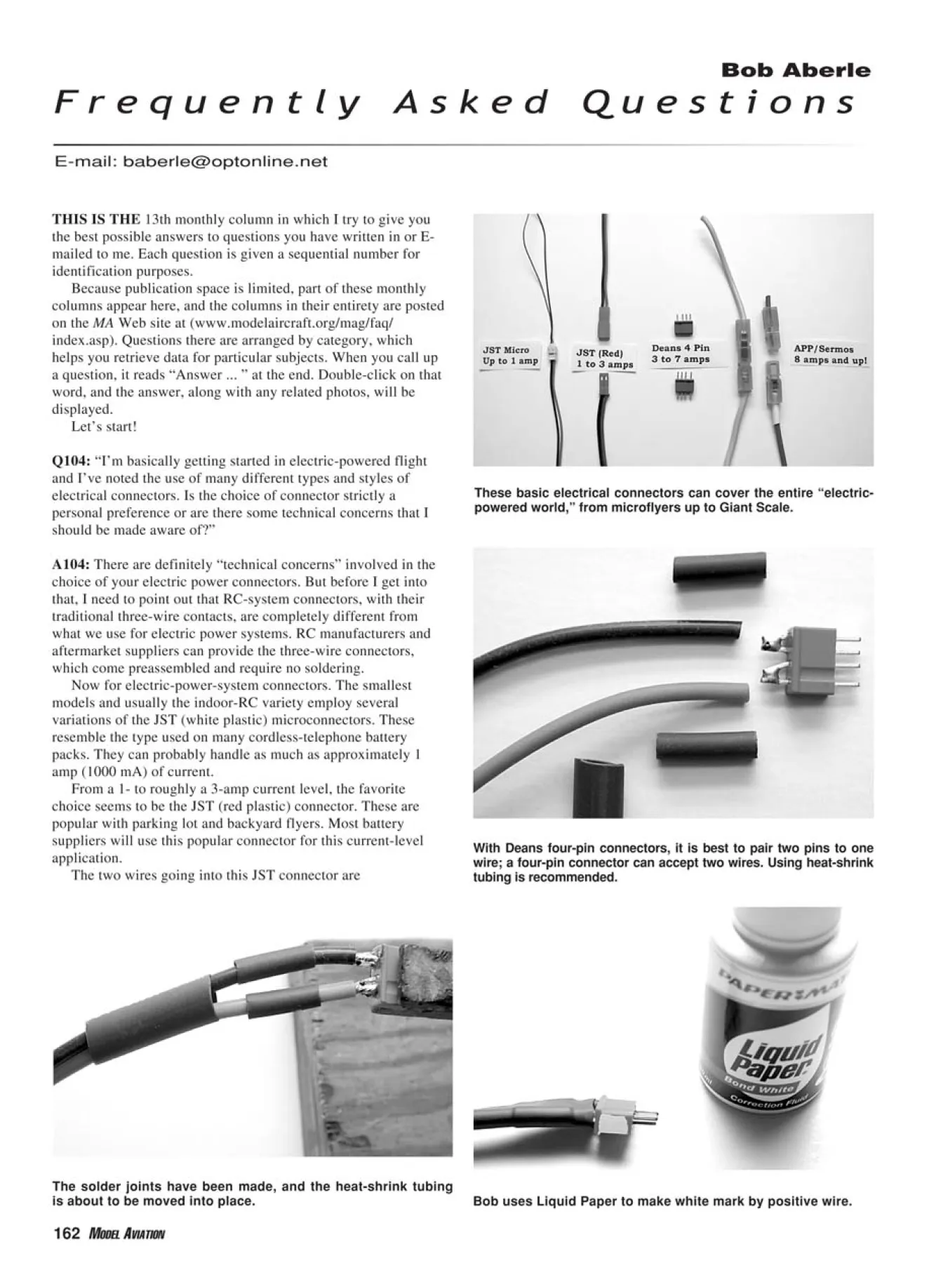
These basic electrical connectors can cover the entire “electricpowered
world,” from microflyers up to Giant Scale.
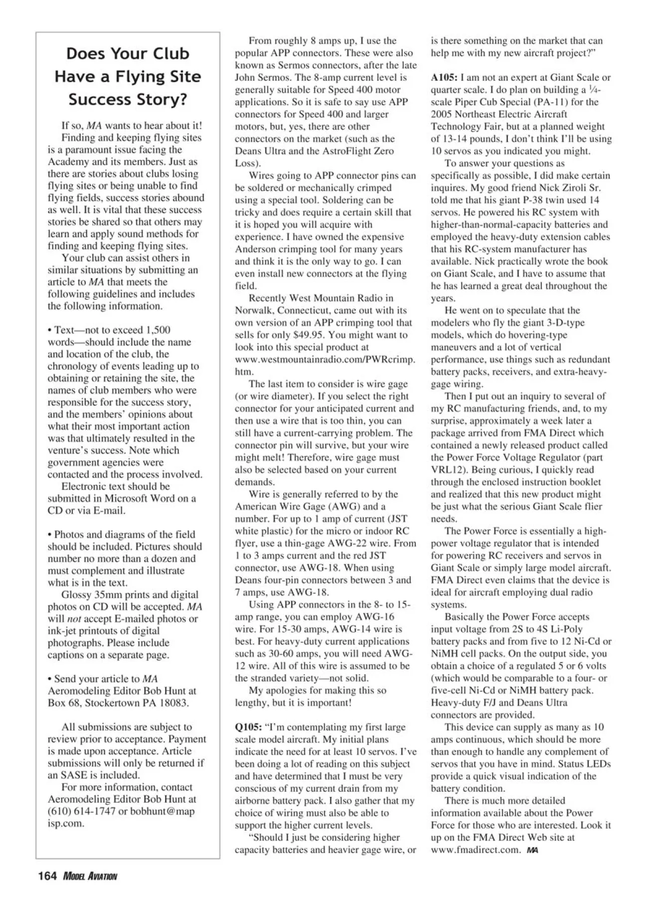
With Deans four-pin connectors, it is best to pair two pins to one
wire; a four-pin connector can accept two wires. Using heat-shrink
tubing is recommended.
THIS IS THE 13th monthly column in which I try to give you
the best possible answers to questions you have written in or Emailed
to me. Each question is given a sequential number for
identification purposes.
Because publication space is limited, part of these monthly
columns appear here, and the columns in their entirety are posted
on the MA Web site at (www.modelaircraft.org/mag/faq/
index.asp). Questions there are arranged by category, which
helps you retrieve data for particular subjects. When you call up
a question, it reads “Answer ... ” at the end. Double-click on that
word, and the answer, along with any related photos, will be
displayed.
Let’s start!
Q104: “I’m basically getting started in electric-powered flight
and I’ve noted the use of many different types and styles of
electrical connectors. Is the choice of connector strictly a
personal preference or are there some technical concerns that I
should be made aware of?”
A104: There are definitely “technical concerns” involved in the
choice of your electric power connectors. But before I get into
that, I need to point out that RC-system connectors, with their
traditional three-wire contacts, are completely different from
what we use for electric power systems. RC manufacturers and
aftermarket suppliers can provide the three-wire connectors,
which come preassembled and require no soldering.
Now for electric-power-system connectors. The smallest
models and usually the indoor-RC variety employ several
variations of the JST (white plastic) microconnectors. These
resemble the type used on many cordless-telephone battery
packs. They can probably handle as much as approximately 1
amp (1000 mA) of current.
From a 1- to roughly a 3-amp current level, the favorite
choice seems to be the JST (red plastic) connector. These are
popular with parking lot and backyard flyers. Most battery
suppliers will use this popular connector for this current-level
application.
The two wires going into this JST connector are
Final connection to Deans connector with larger-diameter heatshrink
tubing over tubing used on individual wires.
FMA Direct’s new Power Force. Basically a voltage-regulating
device, it will accept input power from five to 12 Ni-Cd or NiMH
cells or from 2S to 4S Li-Poly batteries.
Closer look at the Power Force voltage-regulating device. A rear view of the Power Force voltage regulator.
preassembled, so when you purchase a connector it comes with
two pigtail lead wires already attached. You can’t solder the
wires to the pins, so installation requires that you splice into the
existing wiring. Any wire splicing you make must be covered
with heat-shrink tubing to preclude short circuits later.
Some manufacturers and distributors have attempted to
extend the use of the red JST connector up to approximately 8
amps. This is a no-no! I have subjected the red JST connectors to
4 amps of current, and they are already getting hot. By 6 or 7
amps they are beginning to melt.
I questioned one distributor about using this connector for
high-current applications and was told, “We expect that the
modeler will not always use full power and that with normal
throttling back the occasional higher current is acceptable.”
Sorry, I just don’t buy that answer! My limitation for these red
JST connectors is 3 amps maximum, with 2 amps being a better
compromise.
The next step is getting from 2-3 amps up to roughly 7 amps.
I’m still not ready for the Anderson Powerpole (APP)-type
connectors, but what is there to use in between?
I like the Deans four-pin polarized connectors. You can
purchase these from many sources, and they can be easily
soldered. Because we are using only two wires and the connector
has four pins, the common assembly technique is to combine two
pins into one connection. So you end up with one wire going to
two pins and the other wire going to the other two pins. The
photos show this assembly technique.
Which pins you use for positive and negative battery wires is
your choice. My local club establishes a standard for the Deans
pin polarity. That way, everyone using that type of connector at
our field has the same wiring. If you have to borrow a battery
pack at our site, you know it will work.
In that same regard, we place the hook part of our Velcro tape
on the battery pack and the “fuzzy” part on the inside of our
aircraft. This also permits easy swapping of battery packs when
it becomes necessary.
When soldering wires to the Deans four-pin connectors, use
short lengths of heat-shrink tubing to cover the soldered joints.
This acts as a strain relief and prevents accidental shorts. I
usually put a second, larger-diameter length of heat-shrink tubing
over both wires. That makes for easier gripping when you go to
unplug the connector halves. Even though these connectors are
polarized, I place a drop of white correction fluid on the edge
marking the positive pins (red wire usually!).
From roughly 8 amps up, I use the
popular APP connectors. These were also
known as Sermos connectors, after the late
John Sermos. The 8-amp current level is
generally suitable for Speed 400 motor
applications. So it is safe to say use APP
connectors for Speed 400 and larger
motors, but, yes, there are other
connectors on the market (such as the
Deans Ultra and the AstroFlight Zero
Loss).
Wires going to APP connector pins can
be soldered or mechanically crimped
using a special tool. Soldering can be
tricky and does require a certain skill that
it is hoped you will acquire with
experience. I have owned the expensive
Anderson crimping tool for many years
and think it is the only way to go. I can
even install new connectors at the flying
field.
Recently West Mountain Radio in
Norwalk, Connecticut, came out with its
own version of an APP crimping tool that
sells for only $49.95. You might want to
look into this special product at
www.westmountainradio.com/PWRcrimp.
htm.
The last item to consider is wire gage
(or wire diameter). If you select the right
connector for your anticipated current and
then use a wire that is too thin, you can
still have a current-carrying problem. The
connector pin will survive, but your wire
might melt! Therefore, wire gage must
also be selected based on your current
demands.
Wire is generally referred to by the
American Wire Gage (AWG) and a
number. For up to 1 amp of current (JST
white plastic) for the micro or indoor RC
flyer, use a thin-gage AWG-22 wire. From
1 to 3 amps current and the red JST
connector, use AWG-18. When using
Deans four-pin connectors between 3 and
7 amps, use AWG-18.
Using APP connectors in the 8- to 15-
amp range, you can employ AWG-16
wire. For 15-30 amps, AWG-14 wire is
best. For heavy-duty current applications
such as 30-60 amps, you will need AWG-
12 wire. All of this wire is assumed to be
the stranded variety—not solid.
My apologies for making this so
lengthy, but it is important!
Q105: “I’m contemplating my first large
scale model aircraft. My initial plans
indicate the need for at least 10 servos. I’ve
been doing a lot of reading on this subject
and have determined that I must be very
conscious of my current drain from my
airborne battery pack. I also gather that my
choice of wiring must also be able to
support the higher current levels.
“Should I just be considering higher
capacity batteries and heavier gage wire, or
is there something on the market that can
help me with my new aircraft project?”
A105: I am not an expert at Giant Scale or
quarter scale. I do plan on building a 1⁄4-
scale Piper Cub Special (PA-11) for the
2005 Northeast Electric Aircraft
Technology Fair, but at a planned weight
of 13-14 pounds, I don’t think I’ll be using
10 servos as you indicated you might.
To answer your questions as
specifically as possible, I did make certain
inquires. My good friend Nick Ziroli Sr.
told me that his giant P-38 twin used 14
servos. He powered his RC system with
higher-than-normal-capacity batteries and
employed the heavy-duty extension cables
that his RC-system manufacturer has
available. Nick practically wrote the book
on Giant Scale, and I have to assume that
he has learned a great deal throughout the
years.
He went on to speculate that the
modelers who fly the giant 3-D-type
models, which do hovering-type
maneuvers and a lot of vertical
performance, use things such as redundant
battery packs, receivers, and extra-heavygage
wiring.
Then I put out an inquiry to several of
my RC manufacturing friends, and, to my
surprise, approximately a week later a
package arrived from FMA Direct which
contained a newly released product called
the Power Force Voltage Regulator (part
VRL12). Being curious, I quickly read
through the enclosed instruction booklet
and realized that this new product might
be just what the serious Giant Scale flier
needs.
The Power Force is essentially a highpower
voltage regulator that is intended
for powering RC receivers and servos in
Giant Scale or simply large model aircraft.
FMA Direct even claims that the device is
ideal for aircraft employing dual radio
systems.
Basically the Power Force accepts
input voltage from 2S to 4S Li-Poly
battery packs and from five to 12 Ni-Cd or
NiMH cell packs. On the output side, you
obtain a choice of a regulated 5 or 6 volts
(which would be comparable to a four- or
five-cell Ni-Cd or NiMH battery pack.
Heavy-duty F/J and Deans Ultra
connectors are provided.
This device can supply as many as 10
amps continuous, which should be more
than enough to handle any complement of
servos that you have in mind. Status LEDs
provide a quick visual indication of the
battery condition.
There is much more detailed
information available about the Power
Force for those who are interested. Look it
up on the FMA Direct Web site at
www.fmadirect.com. MA
Edition: Model Aviation - 2005/04
Page Numbers: 162,163,164

Edition: Model Aviation - 2005/04
Page Numbers: 162,163,164
Bob Aberle
F r e q u e n t l y A s k e d Q u e s t i o n s
E-mail: [email protected]
Bob uses Liquid Paper to make white mark by positive wire.
The solder joints have been made, and the heat-shrink tubing
is about to be moved into place.
These basic electrical connectors can cover the entire “electricpowered
world,” from microflyers up to Giant Scale.
With Deans four-pin connectors, it is best to pair two pins to one
wire; a four-pin connector can accept two wires. Using heat-shrink
tubing is recommended.
THIS IS THE 13th monthly column in which I try to give you
the best possible answers to questions you have written in or Emailed
to me. Each question is given a sequential number for
identification purposes.
Because publication space is limited, part of these monthly
columns appear here, and the columns in their entirety are posted
on the MA Web site at (www.modelaircraft.org/mag/faq/
index.asp). Questions there are arranged by category, which
helps you retrieve data for particular subjects. When you call up
a question, it reads “Answer ... ” at the end. Double-click on that
word, and the answer, along with any related photos, will be
displayed.
Let’s start!
Q104: “I’m basically getting started in electric-powered flight
and I’ve noted the use of many different types and styles of
electrical connectors. Is the choice of connector strictly a
personal preference or are there some technical concerns that I
should be made aware of?”
A104: There are definitely “technical concerns” involved in the
choice of your electric power connectors. But before I get into
that, I need to point out that RC-system connectors, with their
traditional three-wire contacts, are completely different from
what we use for electric power systems. RC manufacturers and
aftermarket suppliers can provide the three-wire connectors,
which come preassembled and require no soldering.
Now for electric-power-system connectors. The smallest
models and usually the indoor-RC variety employ several
variations of the JST (white plastic) microconnectors. These
resemble the type used on many cordless-telephone battery
packs. They can probably handle as much as approximately 1
amp (1000 mA) of current.
From a 1- to roughly a 3-amp current level, the favorite
choice seems to be the JST (red plastic) connector. These are
popular with parking lot and backyard flyers. Most battery
suppliers will use this popular connector for this current-level
application.
The two wires going into this JST connector are
Final connection to Deans connector with larger-diameter heatshrink
tubing over tubing used on individual wires.
FMA Direct’s new Power Force. Basically a voltage-regulating
device, it will accept input power from five to 12 Ni-Cd or NiMH
cells or from 2S to 4S Li-Poly batteries.
Closer look at the Power Force voltage-regulating device. A rear view of the Power Force voltage regulator.
preassembled, so when you purchase a connector it comes with
two pigtail lead wires already attached. You can’t solder the
wires to the pins, so installation requires that you splice into the
existing wiring. Any wire splicing you make must be covered
with heat-shrink tubing to preclude short circuits later.
Some manufacturers and distributors have attempted to
extend the use of the red JST connector up to approximately 8
amps. This is a no-no! I have subjected the red JST connectors to
4 amps of current, and they are already getting hot. By 6 or 7
amps they are beginning to melt.
I questioned one distributor about using this connector for
high-current applications and was told, “We expect that the
modeler will not always use full power and that with normal
throttling back the occasional higher current is acceptable.”
Sorry, I just don’t buy that answer! My limitation for these red
JST connectors is 3 amps maximum, with 2 amps being a better
compromise.
The next step is getting from 2-3 amps up to roughly 7 amps.
I’m still not ready for the Anderson Powerpole (APP)-type
connectors, but what is there to use in between?
I like the Deans four-pin polarized connectors. You can
purchase these from many sources, and they can be easily
soldered. Because we are using only two wires and the connector
has four pins, the common assembly technique is to combine two
pins into one connection. So you end up with one wire going to
two pins and the other wire going to the other two pins. The
photos show this assembly technique.
Which pins you use for positive and negative battery wires is
your choice. My local club establishes a standard for the Deans
pin polarity. That way, everyone using that type of connector at
our field has the same wiring. If you have to borrow a battery
pack at our site, you know it will work.
In that same regard, we place the hook part of our Velcro tape
on the battery pack and the “fuzzy” part on the inside of our
aircraft. This also permits easy swapping of battery packs when
it becomes necessary.
When soldering wires to the Deans four-pin connectors, use
short lengths of heat-shrink tubing to cover the soldered joints.
This acts as a strain relief and prevents accidental shorts. I
usually put a second, larger-diameter length of heat-shrink tubing
over both wires. That makes for easier gripping when you go to
unplug the connector halves. Even though these connectors are
polarized, I place a drop of white correction fluid on the edge
marking the positive pins (red wire usually!).
From roughly 8 amps up, I use the
popular APP connectors. These were also
known as Sermos connectors, after the late
John Sermos. The 8-amp current level is
generally suitable for Speed 400 motor
applications. So it is safe to say use APP
connectors for Speed 400 and larger
motors, but, yes, there are other
connectors on the market (such as the
Deans Ultra and the AstroFlight Zero
Loss).
Wires going to APP connector pins can
be soldered or mechanically crimped
using a special tool. Soldering can be
tricky and does require a certain skill that
it is hoped you will acquire with
experience. I have owned the expensive
Anderson crimping tool for many years
and think it is the only way to go. I can
even install new connectors at the flying
field.
Recently West Mountain Radio in
Norwalk, Connecticut, came out with its
own version of an APP crimping tool that
sells for only $49.95. You might want to
look into this special product at
www.westmountainradio.com/PWRcrimp.
htm.
The last item to consider is wire gage
(or wire diameter). If you select the right
connector for your anticipated current and
then use a wire that is too thin, you can
still have a current-carrying problem. The
connector pin will survive, but your wire
might melt! Therefore, wire gage must
also be selected based on your current
demands.
Wire is generally referred to by the
American Wire Gage (AWG) and a
number. For up to 1 amp of current (JST
white plastic) for the micro or indoor RC
flyer, use a thin-gage AWG-22 wire. From
1 to 3 amps current and the red JST
connector, use AWG-18. When using
Deans four-pin connectors between 3 and
7 amps, use AWG-18.
Using APP connectors in the 8- to 15-
amp range, you can employ AWG-16
wire. For 15-30 amps, AWG-14 wire is
best. For heavy-duty current applications
such as 30-60 amps, you will need AWG-
12 wire. All of this wire is assumed to be
the stranded variety—not solid.
My apologies for making this so
lengthy, but it is important!
Q105: “I’m contemplating my first large
scale model aircraft. My initial plans
indicate the need for at least 10 servos. I’ve
been doing a lot of reading on this subject
and have determined that I must be very
conscious of my current drain from my
airborne battery pack. I also gather that my
choice of wiring must also be able to
support the higher current levels.
“Should I just be considering higher
capacity batteries and heavier gage wire, or
is there something on the market that can
help me with my new aircraft project?”
A105: I am not an expert at Giant Scale or
quarter scale. I do plan on building a 1⁄4-
scale Piper Cub Special (PA-11) for the
2005 Northeast Electric Aircraft
Technology Fair, but at a planned weight
of 13-14 pounds, I don’t think I’ll be using
10 servos as you indicated you might.
To answer your questions as
specifically as possible, I did make certain
inquires. My good friend Nick Ziroli Sr.
told me that his giant P-38 twin used 14
servos. He powered his RC system with
higher-than-normal-capacity batteries and
employed the heavy-duty extension cables
that his RC-system manufacturer has
available. Nick practically wrote the book
on Giant Scale, and I have to assume that
he has learned a great deal throughout the
years.
He went on to speculate that the
modelers who fly the giant 3-D-type
models, which do hovering-type
maneuvers and a lot of vertical
performance, use things such as redundant
battery packs, receivers, and extra-heavygage
wiring.
Then I put out an inquiry to several of
my RC manufacturing friends, and, to my
surprise, approximately a week later a
package arrived from FMA Direct which
contained a newly released product called
the Power Force Voltage Regulator (part
VRL12). Being curious, I quickly read
through the enclosed instruction booklet
and realized that this new product might
be just what the serious Giant Scale flier
needs.
The Power Force is essentially a highpower
voltage regulator that is intended
for powering RC receivers and servos in
Giant Scale or simply large model aircraft.
FMA Direct even claims that the device is
ideal for aircraft employing dual radio
systems.
Basically the Power Force accepts
input voltage from 2S to 4S Li-Poly
battery packs and from five to 12 Ni-Cd or
NiMH cell packs. On the output side, you
obtain a choice of a regulated 5 or 6 volts
(which would be comparable to a four- or
five-cell Ni-Cd or NiMH battery pack.
Heavy-duty F/J and Deans Ultra
connectors are provided.
This device can supply as many as 10
amps continuous, which should be more
than enough to handle any complement of
servos that you have in mind. Status LEDs
provide a quick visual indication of the
battery condition.
There is much more detailed
information available about the Power
Force for those who are interested. Look it
up on the FMA Direct Web site at
www.fmadirect.com. MA
Edition: Model Aviation - 2005/04
Page Numbers: 162,163,164
Bob Aberle
F r e q u e n t l y A s k e d Q u e s t i o n s
E-mail: [email protected]
Bob uses Liquid Paper to make white mark by positive wire.
The solder joints have been made, and the heat-shrink tubing
is about to be moved into place.
These basic electrical connectors can cover the entire “electricpowered
world,” from microflyers up to Giant Scale.
With Deans four-pin connectors, it is best to pair two pins to one
wire; a four-pin connector can accept two wires. Using heat-shrink
tubing is recommended.
THIS IS THE 13th monthly column in which I try to give you
the best possible answers to questions you have written in or Emailed
to me. Each question is given a sequential number for
identification purposes.
Because publication space is limited, part of these monthly
columns appear here, and the columns in their entirety are posted
on the MA Web site at (www.modelaircraft.org/mag/faq/
index.asp). Questions there are arranged by category, which
helps you retrieve data for particular subjects. When you call up
a question, it reads “Answer ... ” at the end. Double-click on that
word, and the answer, along with any related photos, will be
displayed.
Let’s start!
Q104: “I’m basically getting started in electric-powered flight
and I’ve noted the use of many different types and styles of
electrical connectors. Is the choice of connector strictly a
personal preference or are there some technical concerns that I
should be made aware of?”
A104: There are definitely “technical concerns” involved in the
choice of your electric power connectors. But before I get into
that, I need to point out that RC-system connectors, with their
traditional three-wire contacts, are completely different from
what we use for electric power systems. RC manufacturers and
aftermarket suppliers can provide the three-wire connectors,
which come preassembled and require no soldering.
Now for electric-power-system connectors. The smallest
models and usually the indoor-RC variety employ several
variations of the JST (white plastic) microconnectors. These
resemble the type used on many cordless-telephone battery
packs. They can probably handle as much as approximately 1
amp (1000 mA) of current.
From a 1- to roughly a 3-amp current level, the favorite
choice seems to be the JST (red plastic) connector. These are
popular with parking lot and backyard flyers. Most battery
suppliers will use this popular connector for this current-level
application.
The two wires going into this JST connector are
Final connection to Deans connector with larger-diameter heatshrink
tubing over tubing used on individual wires.
FMA Direct’s new Power Force. Basically a voltage-regulating
device, it will accept input power from five to 12 Ni-Cd or NiMH
cells or from 2S to 4S Li-Poly batteries.
Closer look at the Power Force voltage-regulating device. A rear view of the Power Force voltage regulator.
preassembled, so when you purchase a connector it comes with
two pigtail lead wires already attached. You can’t solder the
wires to the pins, so installation requires that you splice into the
existing wiring. Any wire splicing you make must be covered
with heat-shrink tubing to preclude short circuits later.
Some manufacturers and distributors have attempted to
extend the use of the red JST connector up to approximately 8
amps. This is a no-no! I have subjected the red JST connectors to
4 amps of current, and they are already getting hot. By 6 or 7
amps they are beginning to melt.
I questioned one distributor about using this connector for
high-current applications and was told, “We expect that the
modeler will not always use full power and that with normal
throttling back the occasional higher current is acceptable.”
Sorry, I just don’t buy that answer! My limitation for these red
JST connectors is 3 amps maximum, with 2 amps being a better
compromise.
The next step is getting from 2-3 amps up to roughly 7 amps.
I’m still not ready for the Anderson Powerpole (APP)-type
connectors, but what is there to use in between?
I like the Deans four-pin polarized connectors. You can
purchase these from many sources, and they can be easily
soldered. Because we are using only two wires and the connector
has four pins, the common assembly technique is to combine two
pins into one connection. So you end up with one wire going to
two pins and the other wire going to the other two pins. The
photos show this assembly technique.
Which pins you use for positive and negative battery wires is
your choice. My local club establishes a standard for the Deans
pin polarity. That way, everyone using that type of connector at
our field has the same wiring. If you have to borrow a battery
pack at our site, you know it will work.
In that same regard, we place the hook part of our Velcro tape
on the battery pack and the “fuzzy” part on the inside of our
aircraft. This also permits easy swapping of battery packs when
it becomes necessary.
When soldering wires to the Deans four-pin connectors, use
short lengths of heat-shrink tubing to cover the soldered joints.
This acts as a strain relief and prevents accidental shorts. I
usually put a second, larger-diameter length of heat-shrink tubing
over both wires. That makes for easier gripping when you go to
unplug the connector halves. Even though these connectors are
polarized, I place a drop of white correction fluid on the edge
marking the positive pins (red wire usually!).
From roughly 8 amps up, I use the
popular APP connectors. These were also
known as Sermos connectors, after the late
John Sermos. The 8-amp current level is
generally suitable for Speed 400 motor
applications. So it is safe to say use APP
connectors for Speed 400 and larger
motors, but, yes, there are other
connectors on the market (such as the
Deans Ultra and the AstroFlight Zero
Loss).
Wires going to APP connector pins can
be soldered or mechanically crimped
using a special tool. Soldering can be
tricky and does require a certain skill that
it is hoped you will acquire with
experience. I have owned the expensive
Anderson crimping tool for many years
and think it is the only way to go. I can
even install new connectors at the flying
field.
Recently West Mountain Radio in
Norwalk, Connecticut, came out with its
own version of an APP crimping tool that
sells for only $49.95. You might want to
look into this special product at
www.westmountainradio.com/PWRcrimp.
htm.
The last item to consider is wire gage
(or wire diameter). If you select the right
connector for your anticipated current and
then use a wire that is too thin, you can
still have a current-carrying problem. The
connector pin will survive, but your wire
might melt! Therefore, wire gage must
also be selected based on your current
demands.
Wire is generally referred to by the
American Wire Gage (AWG) and a
number. For up to 1 amp of current (JST
white plastic) for the micro or indoor RC
flyer, use a thin-gage AWG-22 wire. From
1 to 3 amps current and the red JST
connector, use AWG-18. When using
Deans four-pin connectors between 3 and
7 amps, use AWG-18.
Using APP connectors in the 8- to 15-
amp range, you can employ AWG-16
wire. For 15-30 amps, AWG-14 wire is
best. For heavy-duty current applications
such as 30-60 amps, you will need AWG-
12 wire. All of this wire is assumed to be
the stranded variety—not solid.
My apologies for making this so
lengthy, but it is important!
Q105: “I’m contemplating my first large
scale model aircraft. My initial plans
indicate the need for at least 10 servos. I’ve
been doing a lot of reading on this subject
and have determined that I must be very
conscious of my current drain from my
airborne battery pack. I also gather that my
choice of wiring must also be able to
support the higher current levels.
“Should I just be considering higher
capacity batteries and heavier gage wire, or
is there something on the market that can
help me with my new aircraft project?”
A105: I am not an expert at Giant Scale or
quarter scale. I do plan on building a 1⁄4-
scale Piper Cub Special (PA-11) for the
2005 Northeast Electric Aircraft
Technology Fair, but at a planned weight
of 13-14 pounds, I don’t think I’ll be using
10 servos as you indicated you might.
To answer your questions as
specifically as possible, I did make certain
inquires. My good friend Nick Ziroli Sr.
told me that his giant P-38 twin used 14
servos. He powered his RC system with
higher-than-normal-capacity batteries and
employed the heavy-duty extension cables
that his RC-system manufacturer has
available. Nick practically wrote the book
on Giant Scale, and I have to assume that
he has learned a great deal throughout the
years.
He went on to speculate that the
modelers who fly the giant 3-D-type
models, which do hovering-type
maneuvers and a lot of vertical
performance, use things such as redundant
battery packs, receivers, and extra-heavygage
wiring.
Then I put out an inquiry to several of
my RC manufacturing friends, and, to my
surprise, approximately a week later a
package arrived from FMA Direct which
contained a newly released product called
the Power Force Voltage Regulator (part
VRL12). Being curious, I quickly read
through the enclosed instruction booklet
and realized that this new product might
be just what the serious Giant Scale flier
needs.
The Power Force is essentially a highpower
voltage regulator that is intended
for powering RC receivers and servos in
Giant Scale or simply large model aircraft.
FMA Direct even claims that the device is
ideal for aircraft employing dual radio
systems.
Basically the Power Force accepts
input voltage from 2S to 4S Li-Poly
battery packs and from five to 12 Ni-Cd or
NiMH cell packs. On the output side, you
obtain a choice of a regulated 5 or 6 volts
(which would be comparable to a four- or
five-cell Ni-Cd or NiMH battery pack.
Heavy-duty F/J and Deans Ultra
connectors are provided.
This device can supply as many as 10
amps continuous, which should be more
than enough to handle any complement of
servos that you have in mind. Status LEDs
provide a quick visual indication of the
battery condition.
There is much more detailed
information available about the Power
Force for those who are interested. Look it
up on the FMA Direct Web site at
www.fmadirect.com. MA

