
Bob Aberle
F r e q u e n t l y A s k e d Q u e s t i o n s
E-mail: [email protected]
THIS IS THE 15th monthly column in
which I will try to give you the best possible
answers to questions you have written in or
E-mailed to me. Each new question is given
a sequential number for identification
purposes. Because publication space is
limited, part of this column will appear in
print and the columns in their entirety will
be posted on the AMA Web site at
www.modelaircraft.org/mag/faq/index.asp.
There, you can access particular
questions by subject matter or categories;
that allows you to retrieve data for specific
topics. When you call up a question, at the
end it reads “Answer … ” Double-click on
that word, and the answer and any related
photos will be displayed.
Let’s start!
Q116: “I’ve heard that operating flaps can
be added to model aircraft and that they can
provide roughly the same advantages they
do on full-scale aircraft, namely provide
more lift at low flying speeds, especially
when landing.
“Being pretty much a beginner in the RC
hobby I would like try flaps to possibly
make my landing approaches easier (slower)
for me.”
A116: Operating (or deployable) flaps have
been used on RC models for years, with
considerable success. The flaps are located
inboard of the regular aircraft ailerons. The
ailerons produce the model’s roll motion by
banking it left or right. Concurrent with that
“roll action,” the inboard flaps can be
deployed to add lift to the wing, allowing
the airplane to be slowed more than normal,
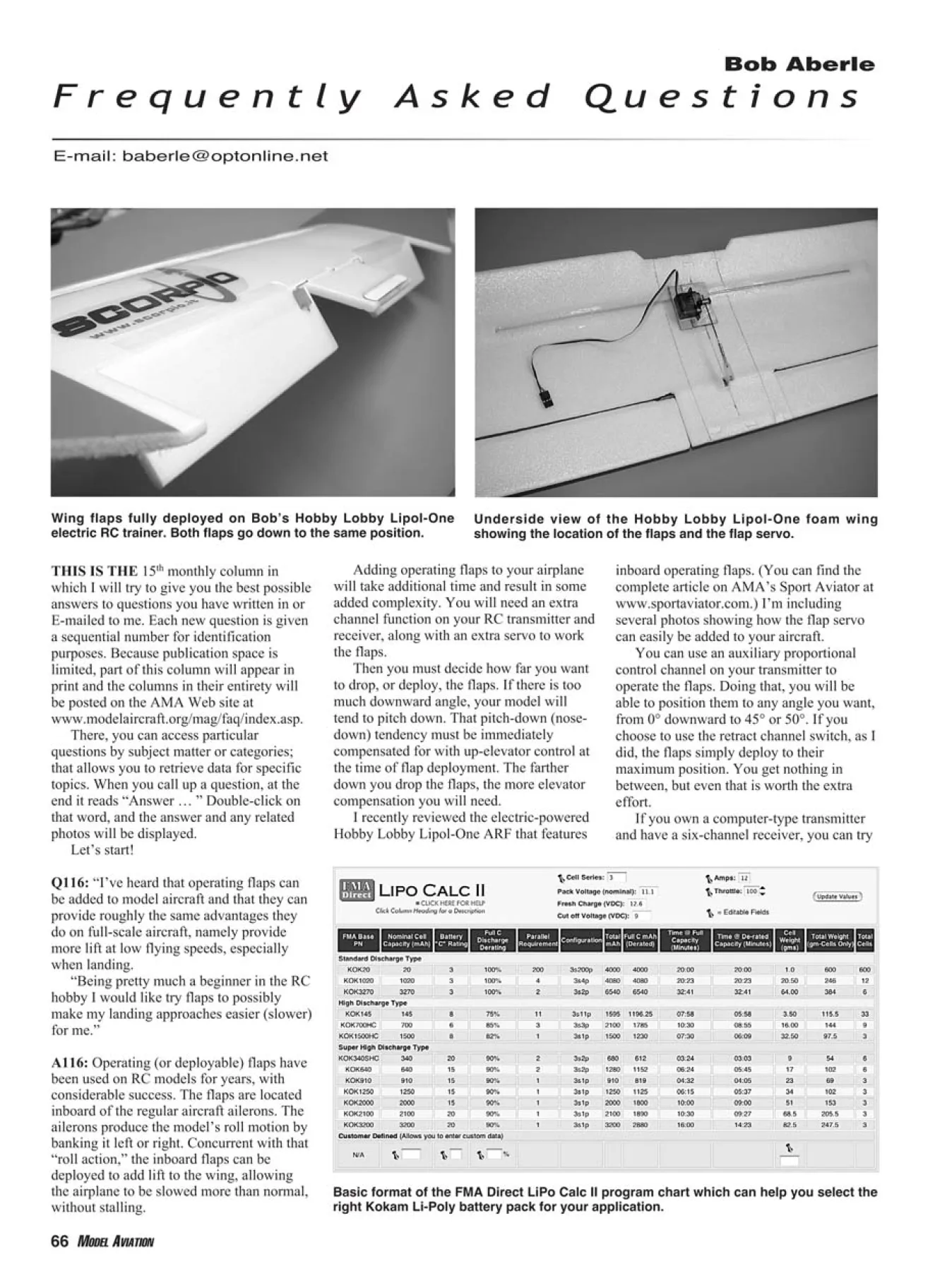
Underside view of the Hobby Lobby Lipol-One foam wing
showing the location of the flaps and the flap servo.
Wing flaps fully deployed on Bob’s Hobby Lobby Lipol-One
electric RC trainer. Both flaps go down to the same position.
without stalling.
Adding operating flaps to your airplane
will take additional time and result in some
added complexity. You will need an extra
channel function on your RC transmitter and
receiver, along with an extra servo to work
the flaps.
Then you must decide how far you want
to drop, or deploy, the flaps. If there is too
much downward angle, your model will
tend to pitch down. That pitch-down (nosedown)
tendency must be immediately
compensated for with up-elevator control at
the time of flap deployment. The farther
down you drop the flaps, the more elevator
compensation you will need.
I recently reviewed the electric-powered
Hobby Lobby Lipol-One ARF that features
inboard operating flaps. (You can find the
complete article on AMA’s Sport Aviator at
www.sportaviator.com.) I’m including
several photos showing how the flap servo
can easily be added to your aircraft.
You can use an auxiliary proportional
control channel on your transmitter to
operate the flaps. Doing that, you will be
able to position them to any angle you want,
from 0° downward to 45° or 50°. If you
choose to use the retract channel switch, as I
did, the flaps simply deploy to their
maximum position. You get nothing in
between, but even that is worth the extra
effort.
If you own a computer-type transmitter
Basic format of the FMA Direct LiPo Calc II program chart which can help you select the
right Kokam Li-Poly battery pack for your application.
68 MODEL AVIATION
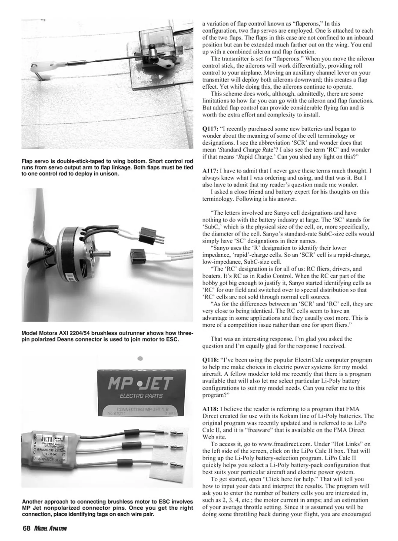
Flap servo is double-stick-taped to wing bottom. Short control rod
runs from servo output arm to flap linkage. Both flaps must be tied
to one control rod to deploy in unison.
Model Motors AXI 2204/54 brushless outrunner shows how threepin
polarized Deans connector is used to join motor to ESC.
Another approach to connecting brushless motor to ESC involves
MP Jet nonpolarized connector pins. Once you get the right
connection, place identifying tags on each wire pair.
and have a six-channel receiver, you can try a variation of flap
control known as “flaperons,” In this configuration, two flap servos
are employed. One is attached to each of the two flaps. The flaps in
this case are not confined to an inboard position but can be extended
much farther out on the wing. You end up with a combined aileron
and flap function.
The transmitter is set for “flaperons.” When you move the aileron
control stick, the ailerons will work differentially, providing roll
control to your airplane. Moving an auxiliary channel lever on your
transmitter will deploy both ailerons downward; this creates a flap
effect. Yet while doing this, the ailerons continue to operate.
This scheme does work, although, admittedly, there are some
limitations to how far you can go with the aileron and flap functions.
But added flap control can provide considerable flying fun and is
worth the extra effort and complexity to install.
Q117: “I recently purchased some new batteries and began to
wonder about the meaning of some of the cell terminology or
designations. I see the abbreviation ‘SCR’ and wonder does that
mean ‘Standard Charge Rate’? I also see the term ‘RC’ and wonder
if that means ‘Rapid Charge.’ Can you shed any light on this?”
A117: I have to admit that I never gave these terms much thought. I
always knew what I was ordering and using, and that was it. But I
also have to admit that my reader’s question made me wonder.
I asked a close friend and battery expert for his thoughts on this
terminology. Following is his answer.
“The letters involved are Sanyo cell designations and have
nothing to do with the battery industry at large. The ‘SC’ stands for
‘SubC,’ which is the physical size of the cell, or, more specifically,
the diameter of the cell. Sanyo’s standard-rate SubC-size cells would
simply have ‘SC’ designations in their names.
“Sanyo uses the ‘R’ designation to identify their lower
impedance, ‘rapid’-charge cells. So an ‘SCR’ cell is a rapid-charge,
low-impedance, SubC-size cell.
“The ‘RC’ designation is for all of us: RC fliers, drivers, and
boaters. It’s RC as in Radio Control. When the RC car part of the
hobby got big enough to justify it, Sanyo started identifying cells as
‘RC’ for our field and switched over to special distribution so that
‘RC’ cells are not sold through normal cell sources.
“As for the differences between an ‘SCR’ and ‘RC’ cell, they are
very close to being identical. The RC cells seem to have an
advantage in some applications and they usually cost more. This is
more of a competition issue rather than one for sport fliers.”
That was an interesting response. I’m glad you asked the
question and I’m equally glad for the response I received.
Q118: “I’ve been using the popular ElectriCalc computer program
to help me make choices in electric power systems for my model
aircraft. A fellow modeler told me recently that there is a program
available that will also let me select particular Li-Poly battery
configurations to suit my model needs. Can you refer me to this
program?”
A118: I believe the reader is referring to a program that FMA
Direct created for use with its Kokam line of Li-Poly batteries. The
original program was recently updated and is referred to as LiPo
Calc II, and it is “freeware” that is available on the FMA Direct
Web site.
To access it, go to www.fmadirect.com. Under “Hot Links” on
the left side of the screen, click on the LiPo Calc II box. That will
bring up the Li-Poly battery-selection program. LiPo Calc II
quickly helps you select a Li-Poly battery-pack configuration that
best suits your particular aircraft and electric power system.
To get started, open “Click here for help.” That will tell you
how to input your data and interpret the results. The program will
ask you to enter the number of battery cells you are interested in,
such as 2, 3, 4, etc.; the motor current in amps; and an estimation
of your average throttle setting. Since it is assumed you will be
doing some throttling back during your
flight, you are encouraged to pick a
number less than 100% or full throttle.
After making the three entries, click
on “Update Values.” Your alternative
battery-pack configurations will appear
in tabular form. It takes awhile to get
used to this program’s format, but the
output information can prove quite
helpful—and the service is free!
Q119: “I just bought my first brushless
electric motor and noticed that unlike all
my previous ferrite motors, this new
motor has three wires coming out of it.
My ferrite motors only required two
wires.
“I also read in the instructions that
come with my brushless motor that if it
runs backward, swap any two of the
three wires to get it to run in the correct
direction. What is that all about? Why
can’t they just supply a wiring diagram
and employ color-coded wires?”
A119: The reader is obviously frustrated
by this seeming lack of instruction for
his new brushless motors. In defense of
the manufacturer(s), the new brushless
motors that operate from what is called a
“sensorless” ESC have become second
nature to most electric enthusiasts. For
that reason, I’m afraid that the
manufacturers are taking their
instruction too casually.
The fact is that these new motors do
have three wires exiting the case. The
companion brushless-motor ESC also has
three input wires. Most manufacturers
suggest using individual, nonpolarized
connector pins (such as MP Jet item
MJ21011 connector pins from Hobby
Lobby) to make the connection of the three
wires between the motor and the ESC.
They suggest that you run up the
motor initially to determine that it is
rotating in the correct direction. With a
forward-facing motor, the rotation should
be counterclockwise and the airflow from
the propwash should blow back toward
the rear, or tail, of the model.
If you find the propeller rotating
opposite to that and the propwash
blowing forward of the aircraft nose,
reverse any two of the three wires and the
rotation will be corrected. After you do
that, you can easily place small tags on
each pair of wires for future
identification.
I like to use multipin polarized
connectors to join my brushless motor
and ESC. Once set up, I can easily move
a particular motor to another model,
which has its own ESC inside the
fuselage. I mount the motor in place, plug
in the connector, and I can go flying. I
even do this at my flying field. It allows
me to share one motor with several
aircraft.
That’s a wrap for “Frequently Asked
Questions” column 15! MA
Edition: Model Aviation - 2005/06
Page Numbers: 66,68,70
Edition: Model Aviation - 2005/06
Page Numbers: 66,68,70
Bob Aberle
F r e q u e n t l y A s k e d Q u e s t i o n s
E-mail: [email protected]
THIS IS THE 15th monthly column in
which I will try to give you the best possible
answers to questions you have written in or
E-mailed to me. Each new question is given
a sequential number for identification
purposes. Because publication space is
limited, part of this column will appear in
print and the columns in their entirety will
be posted on the AMA Web site at
www.modelaircraft.org/mag/faq/index.asp.
There, you can access particular
questions by subject matter or categories;
that allows you to retrieve data for specific
topics. When you call up a question, at the
end it reads “Answer … ” Double-click on
that word, and the answer and any related
photos will be displayed.
Let’s start!
Q116: “I’ve heard that operating flaps can
be added to model aircraft and that they can
provide roughly the same advantages they
do on full-scale aircraft, namely provide
more lift at low flying speeds, especially
when landing.
“Being pretty much a beginner in the RC
hobby I would like try flaps to possibly
make my landing approaches easier (slower)
for me.”
A116: Operating (or deployable) flaps have
been used on RC models for years, with
considerable success. The flaps are located
inboard of the regular aircraft ailerons. The
ailerons produce the model’s roll motion by
banking it left or right. Concurrent with that
“roll action,” the inboard flaps can be
deployed to add lift to the wing, allowing
the airplane to be slowed more than normal,
Underside view of the Hobby Lobby Lipol-One foam wing
showing the location of the flaps and the flap servo.
Wing flaps fully deployed on Bob’s Hobby Lobby Lipol-One
electric RC trainer. Both flaps go down to the same position.
without stalling.
Adding operating flaps to your airplane
will take additional time and result in some
added complexity. You will need an extra
channel function on your RC transmitter and
receiver, along with an extra servo to work
the flaps.
Then you must decide how far you want
to drop, or deploy, the flaps. If there is too
much downward angle, your model will
tend to pitch down. That pitch-down (nosedown)
tendency must be immediately
compensated for with up-elevator control at
the time of flap deployment. The farther
down you drop the flaps, the more elevator
compensation you will need.
I recently reviewed the electric-powered
Hobby Lobby Lipol-One ARF that features
inboard operating flaps. (You can find the
complete article on AMA’s Sport Aviator at
www.sportaviator.com.) I’m including
several photos showing how the flap servo
can easily be added to your aircraft.
You can use an auxiliary proportional
control channel on your transmitter to
operate the flaps. Doing that, you will be
able to position them to any angle you want,
from 0° downward to 45° or 50°. If you
choose to use the retract channel switch, as I
did, the flaps simply deploy to their
maximum position. You get nothing in
between, but even that is worth the extra
effort.
If you own a computer-type transmitter
Basic format of the FMA Direct LiPo Calc II program chart which can help you select the
right Kokam Li-Poly battery pack for your application.
68 MODEL AVIATION
Flap servo is double-stick-taped to wing bottom. Short control rod
runs from servo output arm to flap linkage. Both flaps must be tied
to one control rod to deploy in unison.
Model Motors AXI 2204/54 brushless outrunner shows how threepin
polarized Deans connector is used to join motor to ESC.
Another approach to connecting brushless motor to ESC involves
MP Jet nonpolarized connector pins. Once you get the right
connection, place identifying tags on each wire pair.
and have a six-channel receiver, you can try a variation of flap
control known as “flaperons,” In this configuration, two flap servos
are employed. One is attached to each of the two flaps. The flaps in
this case are not confined to an inboard position but can be extended
much farther out on the wing. You end up with a combined aileron
and flap function.
The transmitter is set for “flaperons.” When you move the aileron
control stick, the ailerons will work differentially, providing roll
control to your airplane. Moving an auxiliary channel lever on your
transmitter will deploy both ailerons downward; this creates a flap
effect. Yet while doing this, the ailerons continue to operate.
This scheme does work, although, admittedly, there are some
limitations to how far you can go with the aileron and flap functions.
But added flap control can provide considerable flying fun and is
worth the extra effort and complexity to install.
Q117: “I recently purchased some new batteries and began to
wonder about the meaning of some of the cell terminology or
designations. I see the abbreviation ‘SCR’ and wonder does that
mean ‘Standard Charge Rate’? I also see the term ‘RC’ and wonder
if that means ‘Rapid Charge.’ Can you shed any light on this?”
A117: I have to admit that I never gave these terms much thought. I
always knew what I was ordering and using, and that was it. But I
also have to admit that my reader’s question made me wonder.
I asked a close friend and battery expert for his thoughts on this
terminology. Following is his answer.
“The letters involved are Sanyo cell designations and have
nothing to do with the battery industry at large. The ‘SC’ stands for
‘SubC,’ which is the physical size of the cell, or, more specifically,
the diameter of the cell. Sanyo’s standard-rate SubC-size cells would
simply have ‘SC’ designations in their names.
“Sanyo uses the ‘R’ designation to identify their lower
impedance, ‘rapid’-charge cells. So an ‘SCR’ cell is a rapid-charge,
low-impedance, SubC-size cell.
“The ‘RC’ designation is for all of us: RC fliers, drivers, and
boaters. It’s RC as in Radio Control. When the RC car part of the
hobby got big enough to justify it, Sanyo started identifying cells as
‘RC’ for our field and switched over to special distribution so that
‘RC’ cells are not sold through normal cell sources.
“As for the differences between an ‘SCR’ and ‘RC’ cell, they are
very close to being identical. The RC cells seem to have an
advantage in some applications and they usually cost more. This is
more of a competition issue rather than one for sport fliers.”
That was an interesting response. I’m glad you asked the
question and I’m equally glad for the response I received.
Q118: “I’ve been using the popular ElectriCalc computer program
to help me make choices in electric power systems for my model
aircraft. A fellow modeler told me recently that there is a program
available that will also let me select particular Li-Poly battery
configurations to suit my model needs. Can you refer me to this
program?”
A118: I believe the reader is referring to a program that FMA
Direct created for use with its Kokam line of Li-Poly batteries. The
original program was recently updated and is referred to as LiPo
Calc II, and it is “freeware” that is available on the FMA Direct
Web site.
To access it, go to www.fmadirect.com. Under “Hot Links” on
the left side of the screen, click on the LiPo Calc II box. That will
bring up the Li-Poly battery-selection program. LiPo Calc II
quickly helps you select a Li-Poly battery-pack configuration that
best suits your particular aircraft and electric power system.
To get started, open “Click here for help.” That will tell you
how to input your data and interpret the results. The program will
ask you to enter the number of battery cells you are interested in,
such as 2, 3, 4, etc.; the motor current in amps; and an estimation
of your average throttle setting. Since it is assumed you will be
doing some throttling back during your
flight, you are encouraged to pick a
number less than 100% or full throttle.
After making the three entries, click
on “Update Values.” Your alternative
battery-pack configurations will appear
in tabular form. It takes awhile to get
used to this program’s format, but the
output information can prove quite
helpful—and the service is free!
Q119: “I just bought my first brushless
electric motor and noticed that unlike all
my previous ferrite motors, this new
motor has three wires coming out of it.
My ferrite motors only required two
wires.
“I also read in the instructions that
come with my brushless motor that if it
runs backward, swap any two of the
three wires to get it to run in the correct
direction. What is that all about? Why
can’t they just supply a wiring diagram
and employ color-coded wires?”
A119: The reader is obviously frustrated
by this seeming lack of instruction for
his new brushless motors. In defense of
the manufacturer(s), the new brushless
motors that operate from what is called a
“sensorless” ESC have become second
nature to most electric enthusiasts. For
that reason, I’m afraid that the
manufacturers are taking their
instruction too casually.
The fact is that these new motors do
have three wires exiting the case. The
companion brushless-motor ESC also has
three input wires. Most manufacturers
suggest using individual, nonpolarized
connector pins (such as MP Jet item
MJ21011 connector pins from Hobby
Lobby) to make the connection of the three
wires between the motor and the ESC.
They suggest that you run up the
motor initially to determine that it is
rotating in the correct direction. With a
forward-facing motor, the rotation should
be counterclockwise and the airflow from
the propwash should blow back toward
the rear, or tail, of the model.
If you find the propeller rotating
opposite to that and the propwash
blowing forward of the aircraft nose,
reverse any two of the three wires and the
rotation will be corrected. After you do
that, you can easily place small tags on
each pair of wires for future
identification.
I like to use multipin polarized
connectors to join my brushless motor
and ESC. Once set up, I can easily move
a particular motor to another model,
which has its own ESC inside the
fuselage. I mount the motor in place, plug
in the connector, and I can go flying. I
even do this at my flying field. It allows
me to share one motor with several
aircraft.
That’s a wrap for “Frequently Asked
Questions” column 15! MA

