
Harry C Shoaf last months installment author discussed tire- making techniques up 2-in diameter wheels Concluding month goes making both wheels tires true big wheels up 7-in diameter -scalers Part 2 CURRENT project 1-scale Curtiss Fledgling full scale tire 30 OD x5 D makes model tire33A OD x D such may classified big tire mold Fig 6 sized 31 OD r sized tight rim fit Since tire over four times amount rubber over biggest yet made allowed two days curing results good although felt 43-gram weight high have light-weight complex anyway gave rise idea making tire hollow felt addi tional work involved would worthwhile because weight savings novelty ldecidedtotry idealusedon a2 x9/32 tire couple ye ars ago experiment worked very well principle thin metal disc used has mandrel around its edge mandrel circular cross section half above half under disc edge centered tire groove form tires hollow center disc fixed position molds alignment pin original experiment 005 brass shim stock disc mandrel made low melting temperature alloy about 2500F formed circular groove soldering iron materials worked small tire felt wouldnt 3 tire used 040 aluminum mandrel disc two piece mandrel wasyou guessed plaster ofparis used template idea employed making molds see Fig 7 produce mandrels disc extended part way mandrel necessitated relieving mandrels inner surface about 020 easily done D square end router bit drill press disc see Fig 8 six tabs about its periphery hole Three holes locate mandrel half wood dowels thus insuring centered tire groove plaster mandrel halves held place heavy thread sewing disc through holes located disc just inner diameter ofthe mandreL See Fig 9 thread later cut loose becomes part rubber tire Realizing thread would reinforce rubber saw opportunity incorporate ply tire structure got piece scrap bridal veil has very porous weave cut piece about two inches ten inches bias cutting bias material can pulled around mandrel will form against mandrel sides wrinkles Use needle thread anchor soit can pulled around periphery held place Once bridal veil ply sewing through Fig 7 Mandrel template used make two-piece mandrels form hole hollow tire 7/i- wheel Action template sweeps mandrel halves evident Material used mandrels plaster paris inner circle holes closes ply disc snugs side mandrel nicely Some talk sewing veils still fabricating tire folks should mentioned about new mandrel generally needed tire After severing threads surface disc plaster will probably need broken up order remove disc can use disc over over plaster mandreL having discs diameter less OD mandrel fairly easy remove Fig 10 shows mandrel mold must noted center part mold halves portion covered disc must relieved accommodate thickness disc case about 020 mold half easy drill press router bit Make dry run assembly mold parts mandrel insure surfaces outboard tire groove will touch Unless danger cracking mold being clamped up o0 oo o0 o0 00000 o0 00 00 Ooo0 Fig 8 mandrel disc has six tabs about its periphery hole Three holes locate mandrel half wood dowels insuring centering tire groove 32 Model Aviation Kodak film container affords impression wheel size inside face far wheel dark disc 1/16 ply brake drum outline Mold tire using same procedure described earlier Again forget spray molds also time mandreL Lay silicone material carefully before fill up grooves time mandrel does some filling guess much lay suggested mandrel inserted first mold filled Twist back forth goes groove Once disc down molds surface judgment can made much material may needed second mold Again little too much better little too little Assemble unit clamp forget two days largest tires rye done far result suggestions ye old editor Bill Winter thought /4 -size scale boys might interested After stewing around awhile resulting mold halves size dinner places 9 across See Fig 11 tire OD 7 cross section diameter 1 hollow has wall thickness 3/16 has nylon net ply inner surface has inner tube sponge rubber slugs eter cut slab stuff left over job local upholsterer done procedure used make large tire just same 3 D mandrel used made two halves plaster fastened edge 1/16 aluminum disc As described before disc centered man drel tire grooves having hole center located alignment pin mandrel fine nylon netbridal veil sewn around material cut bias before about 3 wide 20 long mold half loaded caulk within 3/16 being full because 7/ D mandrel would fill rest groove assembly took nearly whole cartridge make tire Since amount material again ever used factor four five let tire cure three days feel about right paster mandrel destroyed before order removed tire good second tire better shown Fig 12 apparent two big tires quarter size devotees can roll own need interesting side excursion little world tire-making machined pair aluminum molds tire size written about earlier namely 2OD x ired 3 diameter mold maximum could turn unimat lathe bummed some camelback local retread tire place some reason raw retread rubber called camelback no amount questions would produce answer other Thats what call Armed little aluminum mold some camelback headed jeweler friends shop Dave has vulcanizer makes molds connection craft device simply flat plate heating elements Above similar plate screwed down mold hand wheel temperature brought up 3000 F controlled point gadget warming up prepared raw rubber six tires hoping would get least good first specimen clamped vulcanizer 15 minutes 3000F result perfect tire ample flash weighed tire readjusted rest raw stock weight made five perfect vulcanized tires felt good about successful experi ment extra martini before dinneror two As can see producing silicone rubber tire differs making vulcanized rubber tire material method former within modelers reach scope latter may March 1980 33 Fig 6 Mold 3-in tire Note overfill grooves template place Since solid rubber tire weighed 43 grams author evolved pro cedure hollow tires would lighterand novelty Fig 8 Mandrel components assembly two halves disc shown ready assembly Background completed mandrel ply sew Thread cut later becomes part finished tire i-Ig lu Manorel assembly moldnote space will become ttFe practice rubber put mold first mandrel worked position afterward 7-in wl-ieeJ weighs about 340 grams Fig 11 TI- 7- tire meld produces 1- diameter hollow tire Note ample overfill grooves connecting slots ne authors 30 x 5 wheel Fledgling also correct ye editors Aristocrat Two pieces 3/16 wire run side side brass tube bearing filled solder epoxy Gear wires wire wrapped soldered before entering bearing Machine lathes vulcanizers readily available us Making wheels tires isnt very compli cated stay disc wheel covered simulated spoke wheel interested true spoke wheel suggest get Fulton Hungerford has best Although am familiar manufacturing process having observed enjoyed few bull sessions him describing methods would too complicated lengthy article rm going describe possible ways make various wheels would have include simple things like double paper cone thing baby R 0 Gs up intent show what rye used tires Simply put just use central plywood disc dowel hub segments wood glued form rim Fig 13 shows progressive stages simulated covered spoke wheels 2 tire nothing mysterious about kind wheel rm sure hundreds modelers have used same method disc wheel desired instead spokes light balsa piece glued side shaped suit samples shown Fig 13 have 1/16 ply disc eter dowel bearing hole 1/16 diameter drilled through dowel drill press after dowel glued place rim consists segments balsa glued side disc grooved out tire As can see light-weight 1/32 sheet-balsa spoke sections added covered tissue Twelve spokes look about right weight consideration drill holes plywood disc shown sort construction simple strong Variations possible suit whims such wire spokes etc 3 D tire required wheel could take much greater load smaller wheels accomplish designed segmented rim ash wood mounted central disc Fig 14 shows build up sequence design complicated requires additional tools 34 Model Aviation Fig 13 Small wheel build-up sequence style features thin ply center disc balsa rim spokes paper covers Fig 14 Built-up rim components 3- rim Material ash eight sections glued up about circular jig uniformity Fig 15 Him build-up sequence sori5-in Tire iwo pieces eie geu form rim stock Finished rim shown right Note holes used fasten rim lathe face plate Fig 16 3%-in wheel components Ply disc glued rim ready spokes Spokes 1/32 ply about 3/16 wide Fig 17 3%-in wheel cover sections Spokes shown place Wheel ready balsa cover shown right Spokes stabilize hub disc rim assembly Fig 20 Components 7iAin wheel Basic rim shown glued up ready turn shape Finished wheel ready receive rough balsa cover brake drum Balsa covers Aristocrat will protected thin glass painted before tire mounted using Glue Seal Text describes vulcanizing figure numbers prove missing certain overlapping pictures droppedbut deemed wise allow figure sequence text both parts article stand written such lathe hub again hard wood dowel illed take brass tube liner As Fig 15 shows two segmented rim units glued together joints reversed strength rim constructed three four thinner units would tougher need existed rims turned finished discs rough cut strung l glued place should square dowel can make dry cut dowels size discs fit rim placing hub hole drilled piece ood rotating disc blank band saw Clamp plywood place blade will cut greater disc radius want make few cuts inching down final size Glue disc place being careful center plane rotation best can See Fig 16 spokes 1/32 ply about 3/16 wide cut spoke lengths slightly longer hub rim distance eliminated need exact fit placing spoke against hub side See Fig 17 spokes dry sanded flush rim balsa cover stock will fit flat added later spokes structural necessity stabilizes hul disc rim assembly structure now complete wheel returned lathe face plate hub drilled receive 3/16 LD brass tube bearing bearing installed after hub trimmed length flaring tube ends shown Fig 18 balsa wheel covers made up eight pie-shaped segments glued hub spokes rim shaped covers chucking wheel drill press via 3/16 bolt As case smaller wheel covered tire wheel effect wanted its pretty easy stick bunch stainless wire spokes instance would prudent dope silk cover instead paper Assuming wheel now complete paint ready roll mount tire - N 1Y&K2/Nx2$r Fig 18 Wheel bearing 30 x 5 wheel simple journal type brass-wall tube Flared ends tube hold bearing place SPONGE jSILICONE RUBBER J - &BALSA \sXCOVERS PLY TIRERIM DETAIL Fig 19 Tire rim detail scale 74- wheel duplicate -scale rather standard wheel circa 1930a 30 x 5 bonding tire rim using silicone glue seal materiaL Let set 24 hours before rough usage wheel big quarter-size tire basically same design 3 tire exactly twice size disc raft plywood led lightening holes spokes 1/16 ply extended 1 dowel hub double-segmented ash wood rim wheel rim also lathe-turned first disc installed afterward spokes basic pieces shown Fig 20 As smaller 3 wheel discs side have eight pie-shaped balsa pieces grain running radial direction discs glued rim spokes rough state shaped drill press hub lined 7/16 0 D brass tube 1/64 walL bearing structure fairly simple rugged practi cat may however complicate hearts content wire fiberglass etc Fig 19 glves idea rim-tire configuration Fig 21 illustrates completed wheel Brake Drum place weights wheel tire sizes discussed charted below consider numbers average subject modification up down suit particular application 2 OD Wheel 1 Tire solid55 gins 2 WheeL37 gins 3 Total assembled wt92 gms 3 OD Wheel 1 Tire solid428 gins 2 Wheel184 gins 3 Total assembled wt612 gms 334 OD Wheel 1 Tire hollow274 gms 2 Sponge inner tube23 gms 3 Wheel184 gins 4 Total assembled wt481 gms 7A OD Wheel 1Tire180 gins 2Sponge inner tube8 gms 3Wheel153 gms 4Total assembled wt341 gins As matter interest would like know about tire weights show few typical ones following table Fig 22 shows tires exception 7 tire silicone rubber material weighs about 6 ounce per in3 specific gravity roughly calculated volume tires above table arrived 6 ounce per in3 number average due nominal tolerance cross section size example though tire called y somewhat shy because groove mold may have wee bit shallow Also may difference material batch another example 2 x 9/32 tire will float water whereas others will sink other explanation tire might contain some internal air pockets bubbles author does claim wheel structure discussed various sizes opti mum choice materials design however represent combination materials available power tools garage urge prevent boredom setting ran few calculations weight aluminum ma chined wheeL dont think can compete wood author hopes subject material article has eliminated least made easier trouble area modelers particu lariy scale boys March 1980 35 lifted pictures Part provide impression typical range tire sizes including 74 inches diameter Right scale 7%-in wheel tire classic quarter-scaler 30 5 wheel ended up ye eds bia Aristocratoh joyl TIRE SIZEWI GMS WT OZS 1 x 12042 2 x515182 2 x 9/3260212 2 x 5/1693328 3 x d4311520 3 x e2971047 7 x1 tube18806631 *2x55194 * Vulcanized Rubber Tire
Edition: Model Aviation - 1980/03
Page Numbers: 32, 33, 34, 35

Edition: Model Aviation - 1980/03
Page Numbers: 32, 33, 34, 35
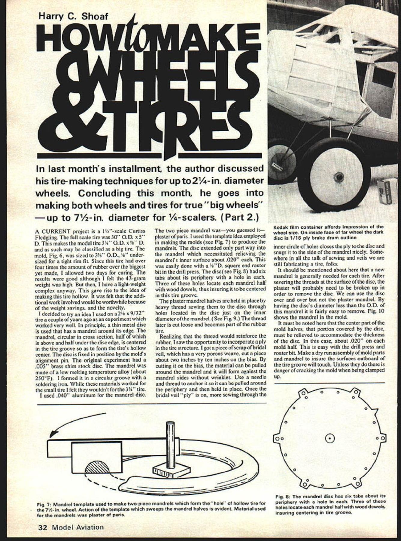
Harry C Shoaf last months installment author discussed tire- making techniques up 2-in diameter wheels Concluding month goes making both wheels tires true big wheels up 7-in diameter -scalers Part 2 CURRENT project 1-scale Curtiss Fledgling full scale tire 30 OD x5 D makes model tire33A OD x D such may classified big tire mold Fig 6 sized 31 OD r sized tight rim fit Since tire over four times amount rubber over biggest yet made allowed two days curing results good although felt 43-gram weight high have light-weight complex anyway gave rise idea making tire hollow felt addi tional work involved would worthwhile because weight savings novelty ldecidedtotry idealusedon a2 x9/32 tire couple ye ars ago experiment worked very well principle thin metal disc used has mandrel around its edge mandrel circular cross section half above half under disc edge centered tire groove form tires hollow center disc fixed position molds alignment pin original experiment 005 brass shim stock disc mandrel made low melting temperature alloy about 2500F formed circular groove soldering iron materials worked small tire felt wouldnt 3 tire used 040 aluminum mandrel disc two piece mandrel wasyou guessed plaster ofparis used template idea employed making molds see Fig 7 produce mandrels disc extended part way mandrel necessitated relieving mandrels inner surface about 020 easily done D square end router bit drill press disc see Fig 8 six tabs about its periphery hole Three holes locate mandrel half wood dowels thus insuring centered tire groove plaster mandrel halves held place heavy thread sewing disc through holes located disc just inner diameter ofthe mandreL See Fig 9 thread later cut loose becomes part rubber tire Realizing thread would reinforce rubber saw opportunity incorporate ply tire structure got piece scrap bridal veil has very porous weave cut piece about two inches ten inches bias cutting bias material can pulled around mandrel will form against mandrel sides wrinkles Use needle thread anchor soit can pulled around periphery held place Once bridal veil ply sewing through Fig 7 Mandrel template used make two-piece mandrels form hole hollow tire 7/i- wheel Action template sweeps mandrel halves evident Material used mandrels plaster paris inner circle holes closes ply disc snugs side mandrel nicely Some talk sewing veils still fabricating tire folks should mentioned about new mandrel generally needed tire After severing threads surface disc plaster will probably need broken up order remove disc can use disc over over plaster mandreL having discs diameter less OD mandrel fairly easy remove Fig 10 shows mandrel mold must noted center part mold halves portion covered disc must relieved accommodate thickness disc case about 020 mold half easy drill press router bit Make dry run assembly mold parts mandrel insure surfaces outboard tire groove will touch Unless danger cracking mold being clamped up o0 oo o0 o0 00000 o0 00 00 Ooo0 Fig 8 mandrel disc has six tabs about its periphery hole Three holes locate mandrel half wood dowels insuring centering tire groove 32 Model Aviation Kodak film container affords impression wheel size inside face far wheel dark disc 1/16 ply brake drum outline Mold tire using same procedure described earlier Again forget spray molds also time mandreL Lay silicone material carefully before fill up grooves time mandrel does some filling guess much lay suggested mandrel inserted first mold filled Twist back forth goes groove Once disc down molds surface judgment can made much material may needed second mold Again little too much better little too little Assemble unit clamp forget two days largest tires rye done far result suggestions ye old editor Bill Winter thought /4 -size scale boys might interested After stewing around awhile resulting mold halves size dinner places 9 across See Fig 11 tire OD 7 cross section diameter 1 hollow has wall thickness 3/16 has nylon net ply inner surface has inner tube sponge rubber slugs eter cut slab stuff left over job local upholsterer done procedure used make large tire just same 3 D mandrel used made two halves plaster fastened edge 1/16 aluminum disc As described before disc centered man drel tire grooves having hole center located alignment pin mandrel fine nylon netbridal veil sewn around material cut bias before about 3 wide 20 long mold half loaded caulk within 3/16 being full because 7/ D mandrel would fill rest groove assembly took nearly whole cartridge make tire Since amount material again ever used factor four five let tire cure three days feel about right paster mandrel destroyed before order removed tire good second tire better shown Fig 12 apparent two big tires quarter size devotees can roll own need interesting side excursion little world tire-making machined pair aluminum molds tire size written about earlier namely 2OD x ired 3 diameter mold maximum could turn unimat lathe bummed some camelback local retread tire place some reason raw retread rubber called camelback no amount questions would produce answer other Thats what call Armed little aluminum mold some camelback headed jeweler friends shop Dave has vulcanizer makes molds connection craft device simply flat plate heating elements Above similar plate screwed down mold hand wheel temperature brought up 3000 F controlled point gadget warming up prepared raw rubber six tires hoping would get least good first specimen clamped vulcanizer 15 minutes 3000F result perfect tire ample flash weighed tire readjusted rest raw stock weight made five perfect vulcanized tires felt good about successful experi ment extra martini before dinneror two As can see producing silicone rubber tire differs making vulcanized rubber tire material method former within modelers reach scope latter may March 1980 33 Fig 6 Mold 3-in tire Note overfill grooves template place Since solid rubber tire weighed 43 grams author evolved pro cedure hollow tires would lighterand novelty Fig 8 Mandrel components assembly two halves disc shown ready assembly Background completed mandrel ply sew Thread cut later becomes part finished tire i-Ig lu Manorel assembly moldnote space will become ttFe practice rubber put mold first mandrel worked position afterward 7-in wl-ieeJ weighs about 340 grams Fig 11 TI- 7- tire meld produces 1- diameter hollow tire Note ample overfill grooves connecting slots ne authors 30 x 5 wheel Fledgling also correct ye editors Aristocrat Two pieces 3/16 wire run side side brass tube bearing filled solder epoxy Gear wires wire wrapped soldered before entering bearing Machine lathes vulcanizers readily available us Making wheels tires isnt very compli cated stay disc wheel covered simulated spoke wheel interested true spoke wheel suggest get Fulton Hungerford has best Although am familiar manufacturing process having observed enjoyed few bull sessions him describing methods would too complicated lengthy article rm going describe possible ways make various wheels would have include simple things like double paper cone thing baby R 0 Gs up intent show what rye used tires Simply put just use central plywood disc dowel hub segments wood glued form rim Fig 13 shows progressive stages simulated covered spoke wheels 2 tire nothing mysterious about kind wheel rm sure hundreds modelers have used same method disc wheel desired instead spokes light balsa piece glued side shaped suit samples shown Fig 13 have 1/16 ply disc eter dowel bearing hole 1/16 diameter drilled through dowel drill press after dowel glued place rim consists segments balsa glued side disc grooved out tire As can see light-weight 1/32 sheet-balsa spoke sections added covered tissue Twelve spokes look about right weight consideration drill holes plywood disc shown sort construction simple strong Variations possible suit whims such wire spokes etc 3 D tire required wheel could take much greater load smaller wheels accomplish designed segmented rim ash wood mounted central disc Fig 14 shows build up sequence design complicated requires additional tools 34 Model Aviation Fig 13 Small wheel build-up sequence style features thin ply center disc balsa rim spokes paper covers Fig 14 Built-up rim components 3- rim Material ash eight sections glued up about circular jig uniformity Fig 15 Him build-up sequence sori5-in Tire iwo pieces eie geu form rim stock Finished rim shown right Note holes used fasten rim lathe face plate Fig 16 3%-in wheel components Ply disc glued rim ready spokes Spokes 1/32 ply about 3/16 wide Fig 17 3%-in wheel cover sections Spokes shown place Wheel ready balsa cover shown right Spokes stabilize hub disc rim assembly Fig 20 Components 7iAin wheel Basic rim shown glued up ready turn shape Finished wheel ready receive rough balsa cover brake drum Balsa covers Aristocrat will protected thin glass painted before tire mounted using Glue Seal Text describes vulcanizing figure numbers prove missing certain overlapping pictures droppedbut deemed wise allow figure sequence text both parts article stand written such lathe hub again hard wood dowel illed take brass tube liner As Fig 15 shows two segmented rim units glued together joints reversed strength rim constructed three four thinner units would tougher need existed rims turned finished discs rough cut strung l glued place should square dowel can make dry cut dowels size discs fit rim placing hub hole drilled piece ood rotating disc blank band saw Clamp plywood place blade will cut greater disc radius want make few cuts inching down final size Glue disc place being careful center plane rotation best can See Fig 16 spokes 1/32 ply about 3/16 wide cut spoke lengths slightly longer hub rim distance eliminated need exact fit placing spoke against hub side See Fig 17 spokes dry sanded flush rim balsa cover stock will fit flat added later spokes structural necessity stabilizes hul disc rim assembly structure now complete wheel returned lathe face plate hub drilled receive 3/16 LD brass tube bearing bearing installed after hub trimmed length flaring tube ends shown Fig 18 balsa wheel covers made up eight pie-shaped segments glued hub spokes rim shaped covers chucking wheel drill press via 3/16 bolt As case smaller wheel covered tire wheel effect wanted its pretty easy stick bunch stainless wire spokes instance would prudent dope silk cover instead paper Assuming wheel now complete paint ready roll mount tire - N 1Y&K2/Nx2$r Fig 18 Wheel bearing 30 x 5 wheel simple journal type brass-wall tube Flared ends tube hold bearing place SPONGE jSILICONE RUBBER J - &BALSA \sXCOVERS PLY TIRERIM DETAIL Fig 19 Tire rim detail scale 74- wheel duplicate -scale rather standard wheel circa 1930a 30 x 5 bonding tire rim using silicone glue seal materiaL Let set 24 hours before rough usage wheel big quarter-size tire basically same design 3 tire exactly twice size disc raft plywood led lightening holes spokes 1/16 ply extended 1 dowel hub double-segmented ash wood rim wheel rim also lathe-turned first disc installed afterward spokes basic pieces shown Fig 20 As smaller 3 wheel discs side have eight pie-shaped balsa pieces grain running radial direction discs glued rim spokes rough state shaped drill press hub lined 7/16 0 D brass tube 1/64 walL bearing structure fairly simple rugged practi cat may however complicate hearts content wire fiberglass etc Fig 19 glves idea rim-tire configuration Fig 21 illustrates completed wheel Brake Drum place weights wheel tire sizes discussed charted below consider numbers average subject modification up down suit particular application 2 OD Wheel 1 Tire solid55 gins 2 WheeL37 gins 3 Total assembled wt92 gms 3 OD Wheel 1 Tire solid428 gins 2 Wheel184 gins 3 Total assembled wt612 gms 334 OD Wheel 1 Tire hollow274 gms 2 Sponge inner tube23 gms 3 Wheel184 gins 4 Total assembled wt481 gms 7A OD Wheel 1Tire180 gins 2Sponge inner tube8 gms 3Wheel153 gms 4Total assembled wt341 gins As matter interest would like know about tire weights show few typical ones following table Fig 22 shows tires exception 7 tire silicone rubber material weighs about 6 ounce per in3 specific gravity roughly calculated volume tires above table arrived 6 ounce per in3 number average due nominal tolerance cross section size example though tire called y somewhat shy because groove mold may have wee bit shallow Also may difference material batch another example 2 x 9/32 tire will float water whereas others will sink other explanation tire might contain some internal air pockets bubbles author does claim wheel structure discussed various sizes opti mum choice materials design however represent combination materials available power tools garage urge prevent boredom setting ran few calculations weight aluminum ma chined wheeL dont think can compete wood author hopes subject material article has eliminated least made easier trouble area modelers particu lariy scale boys March 1980 35 lifted pictures Part provide impression typical range tire sizes including 74 inches diameter Right scale 7%-in wheel tire classic quarter-scaler 30 5 wheel ended up ye eds bia Aristocratoh joyl TIRE SIZEWI GMS WT OZS 1 x 12042 2 x515182 2 x 9/3260212 2 x 5/1693328 3 x d4311520 3 x e2971047 7 x1 tube18806631 *2x55194 * Vulcanized Rubber Tire

Edition: Model Aviation - 1980/03
Page Numbers: 32, 33, 34, 35
Harry C Shoaf last months installment author discussed tire- making techniques up 2-in diameter wheels Concluding month goes making both wheels tires true big wheels up 7-in diameter -scalers Part 2 CURRENT project 1-scale Curtiss Fledgling full scale tire 30 OD x5 D makes model tire33A OD x D such may classified big tire mold Fig 6 sized 31 OD r sized tight rim fit Since tire over four times amount rubber over biggest yet made allowed two days curing results good although felt 43-gram weight high have light-weight complex anyway gave rise idea making tire hollow felt addi tional work involved would worthwhile because weight savings novelty ldecidedtotry idealusedon a2 x9/32 tire couple ye ars ago experiment worked very well principle thin metal disc used has mandrel around its edge mandrel circular cross section half above half under disc edge centered tire groove form tires hollow center disc fixed position molds alignment pin original experiment 005 brass shim stock disc mandrel made low melting temperature alloy about 2500F formed circular groove soldering iron materials worked small tire felt wouldnt 3 tire used 040 aluminum mandrel disc two piece mandrel wasyou guessed plaster ofparis used template idea employed making molds see Fig 7 produce mandrels disc extended part way mandrel necessitated relieving mandrels inner surface about 020 easily done D square end router bit drill press disc see Fig 8 six tabs about its periphery hole Three holes locate mandrel half wood dowels thus insuring centered tire groove plaster mandrel halves held place heavy thread sewing disc through holes located disc just inner diameter ofthe mandreL See Fig 9 thread later cut loose becomes part rubber tire Realizing thread would reinforce rubber saw opportunity incorporate ply tire structure got piece scrap bridal veil has very porous weave cut piece about two inches ten inches bias cutting bias material can pulled around mandrel will form against mandrel sides wrinkles Use needle thread anchor soit can pulled around periphery held place Once bridal veil ply sewing through Fig 7 Mandrel template used make two-piece mandrels form hole hollow tire 7/i- wheel Action template sweeps mandrel halves evident Material used mandrels plaster paris inner circle holes closes ply disc snugs side mandrel nicely Some talk sewing veils still fabricating tire folks should mentioned about new mandrel generally needed tire After severing threads surface disc plaster will probably need broken up order remove disc can use disc over over plaster mandreL having discs diameter less OD mandrel fairly easy remove Fig 10 shows mandrel mold must noted center part mold halves portion covered disc must relieved accommodate thickness disc case about 020 mold half easy drill press router bit Make dry run assembly mold parts mandrel insure surfaces outboard tire groove will touch Unless danger cracking mold being clamped up o0 oo o0 o0 00000 o0 00 00 Ooo0 Fig 8 mandrel disc has six tabs about its periphery hole Three holes locate mandrel half wood dowels insuring centering tire groove 32 Model Aviation Kodak film container affords impression wheel size inside face far wheel dark disc 1/16 ply brake drum outline Mold tire using same procedure described earlier Again forget spray molds also time mandreL Lay silicone material carefully before fill up grooves time mandrel does some filling guess much lay suggested mandrel inserted first mold filled Twist back forth goes groove Once disc down molds surface judgment can made much material may needed second mold Again little too much better little too little Assemble unit clamp forget two days largest tires rye done far result suggestions ye old editor Bill Winter thought /4 -size scale boys might interested After stewing around awhile resulting mold halves size dinner places 9 across See Fig 11 tire OD 7 cross section diameter 1 hollow has wall thickness 3/16 has nylon net ply inner surface has inner tube sponge rubber slugs eter cut slab stuff left over job local upholsterer done procedure used make large tire just same 3 D mandrel used made two halves plaster fastened edge 1/16 aluminum disc As described before disc centered man drel tire grooves having hole center located alignment pin mandrel fine nylon netbridal veil sewn around material cut bias before about 3 wide 20 long mold half loaded caulk within 3/16 being full because 7/ D mandrel would fill rest groove assembly took nearly whole cartridge make tire Since amount material again ever used factor four five let tire cure three days feel about right paster mandrel destroyed before order removed tire good second tire better shown Fig 12 apparent two big tires quarter size devotees can roll own need interesting side excursion little world tire-making machined pair aluminum molds tire size written about earlier namely 2OD x ired 3 diameter mold maximum could turn unimat lathe bummed some camelback local retread tire place some reason raw retread rubber called camelback no amount questions would produce answer other Thats what call Armed little aluminum mold some camelback headed jeweler friends shop Dave has vulcanizer makes molds connection craft device simply flat plate heating elements Above similar plate screwed down mold hand wheel temperature brought up 3000 F controlled point gadget warming up prepared raw rubber six tires hoping would get least good first specimen clamped vulcanizer 15 minutes 3000F result perfect tire ample flash weighed tire readjusted rest raw stock weight made five perfect vulcanized tires felt good about successful experi ment extra martini before dinneror two As can see producing silicone rubber tire differs making vulcanized rubber tire material method former within modelers reach scope latter may March 1980 33 Fig 6 Mold 3-in tire Note overfill grooves template place Since solid rubber tire weighed 43 grams author evolved pro cedure hollow tires would lighterand novelty Fig 8 Mandrel components assembly two halves disc shown ready assembly Background completed mandrel ply sew Thread cut later becomes part finished tire i-Ig lu Manorel assembly moldnote space will become ttFe practice rubber put mold first mandrel worked position afterward 7-in wl-ieeJ weighs about 340 grams Fig 11 TI- 7- tire meld produces 1- diameter hollow tire Note ample overfill grooves connecting slots ne authors 30 x 5 wheel Fledgling also correct ye editors Aristocrat Two pieces 3/16 wire run side side brass tube bearing filled solder epoxy Gear wires wire wrapped soldered before entering bearing Machine lathes vulcanizers readily available us Making wheels tires isnt very compli cated stay disc wheel covered simulated spoke wheel interested true spoke wheel suggest get Fulton Hungerford has best Although am familiar manufacturing process having observed enjoyed few bull sessions him describing methods would too complicated lengthy article rm going describe possible ways make various wheels would have include simple things like double paper cone thing baby R 0 Gs up intent show what rye used tires Simply put just use central plywood disc dowel hub segments wood glued form rim Fig 13 shows progressive stages simulated covered spoke wheels 2 tire nothing mysterious about kind wheel rm sure hundreds modelers have used same method disc wheel desired instead spokes light balsa piece glued side shaped suit samples shown Fig 13 have 1/16 ply disc eter dowel bearing hole 1/16 diameter drilled through dowel drill press after dowel glued place rim consists segments balsa glued side disc grooved out tire As can see light-weight 1/32 sheet-balsa spoke sections added covered tissue Twelve spokes look about right weight consideration drill holes plywood disc shown sort construction simple strong Variations possible suit whims such wire spokes etc 3 D tire required wheel could take much greater load smaller wheels accomplish designed segmented rim ash wood mounted central disc Fig 14 shows build up sequence design complicated requires additional tools 34 Model Aviation Fig 13 Small wheel build-up sequence style features thin ply center disc balsa rim spokes paper covers Fig 14 Built-up rim components 3- rim Material ash eight sections glued up about circular jig uniformity Fig 15 Him build-up sequence sori5-in Tire iwo pieces eie geu form rim stock Finished rim shown right Note holes used fasten rim lathe face plate Fig 16 3%-in wheel components Ply disc glued rim ready spokes Spokes 1/32 ply about 3/16 wide Fig 17 3%-in wheel cover sections Spokes shown place Wheel ready balsa cover shown right Spokes stabilize hub disc rim assembly Fig 20 Components 7iAin wheel Basic rim shown glued up ready turn shape Finished wheel ready receive rough balsa cover brake drum Balsa covers Aristocrat will protected thin glass painted before tire mounted using Glue Seal Text describes vulcanizing figure numbers prove missing certain overlapping pictures droppedbut deemed wise allow figure sequence text both parts article stand written such lathe hub again hard wood dowel illed take brass tube liner As Fig 15 shows two segmented rim units glued together joints reversed strength rim constructed three four thinner units would tougher need existed rims turned finished discs rough cut strung l glued place should square dowel can make dry cut dowels size discs fit rim placing hub hole drilled piece ood rotating disc blank band saw Clamp plywood place blade will cut greater disc radius want make few cuts inching down final size Glue disc place being careful center plane rotation best can See Fig 16 spokes 1/32 ply about 3/16 wide cut spoke lengths slightly longer hub rim distance eliminated need exact fit placing spoke against hub side See Fig 17 spokes dry sanded flush rim balsa cover stock will fit flat added later spokes structural necessity stabilizes hul disc rim assembly structure now complete wheel returned lathe face plate hub drilled receive 3/16 LD brass tube bearing bearing installed after hub trimmed length flaring tube ends shown Fig 18 balsa wheel covers made up eight pie-shaped segments glued hub spokes rim shaped covers chucking wheel drill press via 3/16 bolt As case smaller wheel covered tire wheel effect wanted its pretty easy stick bunch stainless wire spokes instance would prudent dope silk cover instead paper Assuming wheel now complete paint ready roll mount tire - N 1Y&K2/Nx2$r Fig 18 Wheel bearing 30 x 5 wheel simple journal type brass-wall tube Flared ends tube hold bearing place SPONGE jSILICONE RUBBER J - &BALSA \sXCOVERS PLY TIRERIM DETAIL Fig 19 Tire rim detail scale 74- wheel duplicate -scale rather standard wheel circa 1930a 30 x 5 bonding tire rim using silicone glue seal materiaL Let set 24 hours before rough usage wheel big quarter-size tire basically same design 3 tire exactly twice size disc raft plywood led lightening holes spokes 1/16 ply extended 1 dowel hub double-segmented ash wood rim wheel rim also lathe-turned first disc installed afterward spokes basic pieces shown Fig 20 As smaller 3 wheel discs side have eight pie-shaped balsa pieces grain running radial direction discs glued rim spokes rough state shaped drill press hub lined 7/16 0 D brass tube 1/64 walL bearing structure fairly simple rugged practi cat may however complicate hearts content wire fiberglass etc Fig 19 glves idea rim-tire configuration Fig 21 illustrates completed wheel Brake Drum place weights wheel tire sizes discussed charted below consider numbers average subject modification up down suit particular application 2 OD Wheel 1 Tire solid55 gins 2 WheeL37 gins 3 Total assembled wt92 gms 3 OD Wheel 1 Tire solid428 gins 2 Wheel184 gins 3 Total assembled wt612 gms 334 OD Wheel 1 Tire hollow274 gms 2 Sponge inner tube23 gms 3 Wheel184 gins 4 Total assembled wt481 gms 7A OD Wheel 1Tire180 gins 2Sponge inner tube8 gms 3Wheel153 gms 4Total assembled wt341 gins As matter interest would like know about tire weights show few typical ones following table Fig 22 shows tires exception 7 tire silicone rubber material weighs about 6 ounce per in3 specific gravity roughly calculated volume tires above table arrived 6 ounce per in3 number average due nominal tolerance cross section size example though tire called y somewhat shy because groove mold may have wee bit shallow Also may difference material batch another example 2 x 9/32 tire will float water whereas others will sink other explanation tire might contain some internal air pockets bubbles author does claim wheel structure discussed various sizes opti mum choice materials design however represent combination materials available power tools garage urge prevent boredom setting ran few calculations weight aluminum ma chined wheeL dont think can compete wood author hopes subject material article has eliminated least made easier trouble area modelers particu lariy scale boys March 1980 35 lifted pictures Part provide impression typical range tire sizes including 74 inches diameter Right scale 7%-in wheel tire classic quarter-scaler 30 5 wheel ended up ye eds bia Aristocratoh joyl TIRE SIZEWI GMS WT OZS 1 x 12042 2 x515182 2 x 9/3260212 2 x 5/1693328 3 x d4311520 3 x e2971047 7 x1 tube18806631 *2x55194 * Vulcanized Rubber Tire

