
July 2006 17
THE INDY 400 represents an evolution of a 20- to 25-size
prototype I originally designed several years ago. Using many of
the design articles and principles I had seen in Radio Control
Modeler magazine throughout the years, I came up with an easybuilding
design I felt would fly quite well with a .20-.25 power
plant.
My goal in taking this step, in creating the final Indy 400, was
primarily to improve the overall aesthetics, weight, and
aerodynamics of the aircraft. The final version of the model is a
much sleeker, more swoopy and racy version of my original
design. It’s cool-lookin’!
The new version has benefited from my lessening the overall
weight, and its sleekness has increased the aircraft’s top speed.
Because of its reasonable size you will always have room in your
car to take the Indy 400 to the flying field. It is such a good allaround,
fun-to-fly model that it might become one of your
favorites to grab each time you head out.
Several local pilots are currently flying this design or the
earlier version. They encouraged me to do this construction article
because they enjoy the airplane so much. The Indy 400 has
become one of their favorite airplanes.
Why the “Indy 400” name? Many residents of Central Indiana,
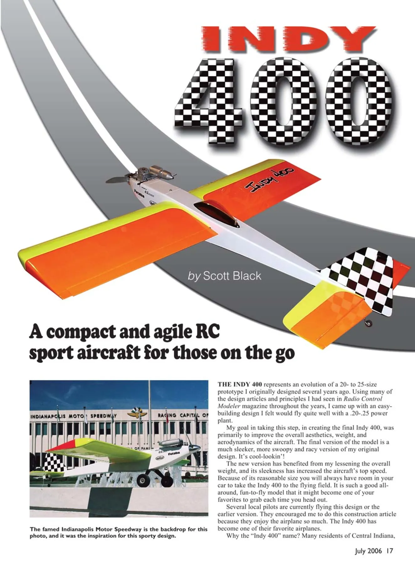
The famed Indianapolis Motor Speedway is the backdrop for this
photo, and it was the inspiration for this sporty design.
by Scott Black
A compact and agile RC
sport aircraft for those on the go
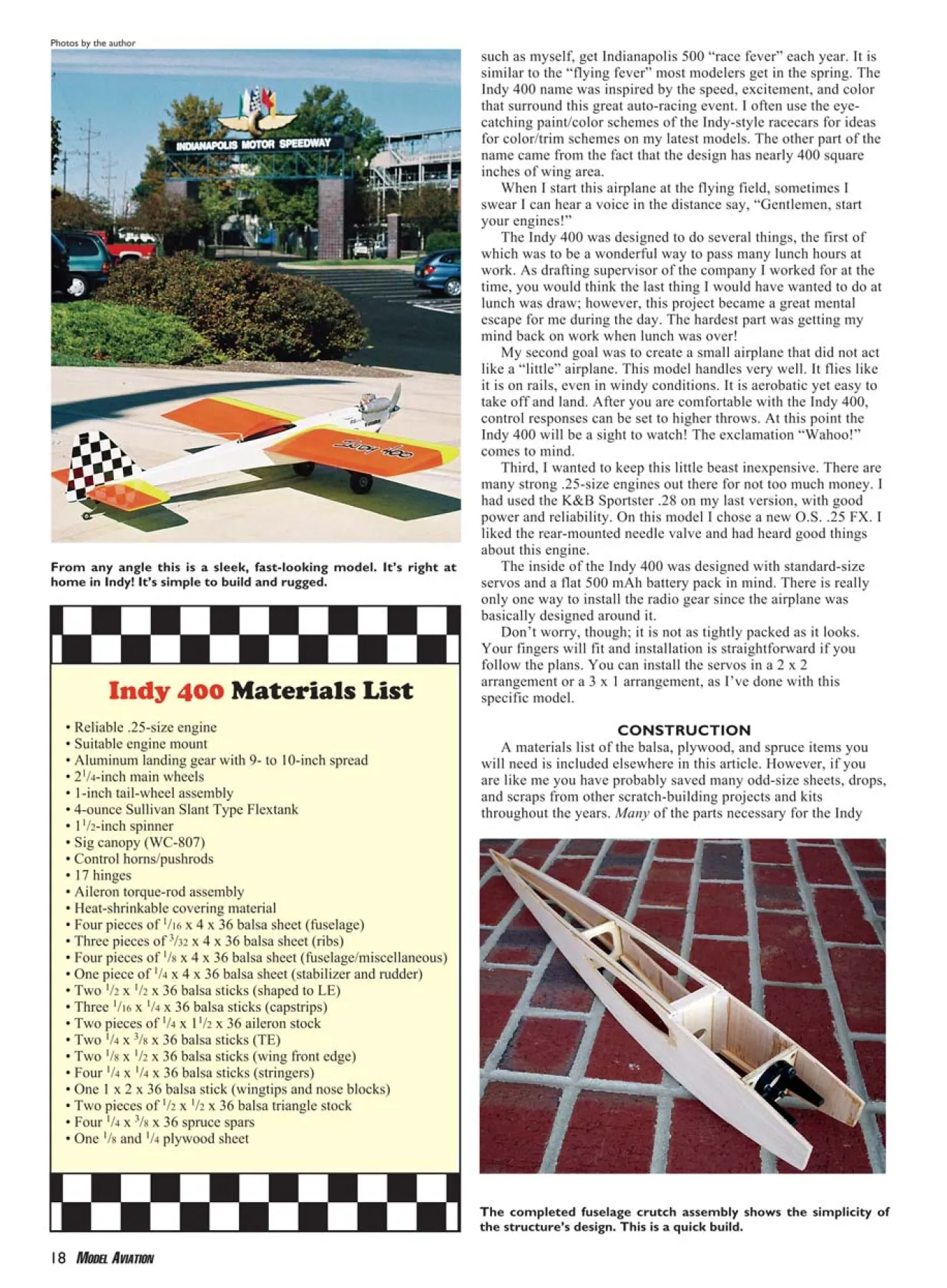
From any angle this is a sleek, fast-looking model. It’s right at
home in Indy! It’s simple to build and rugged.
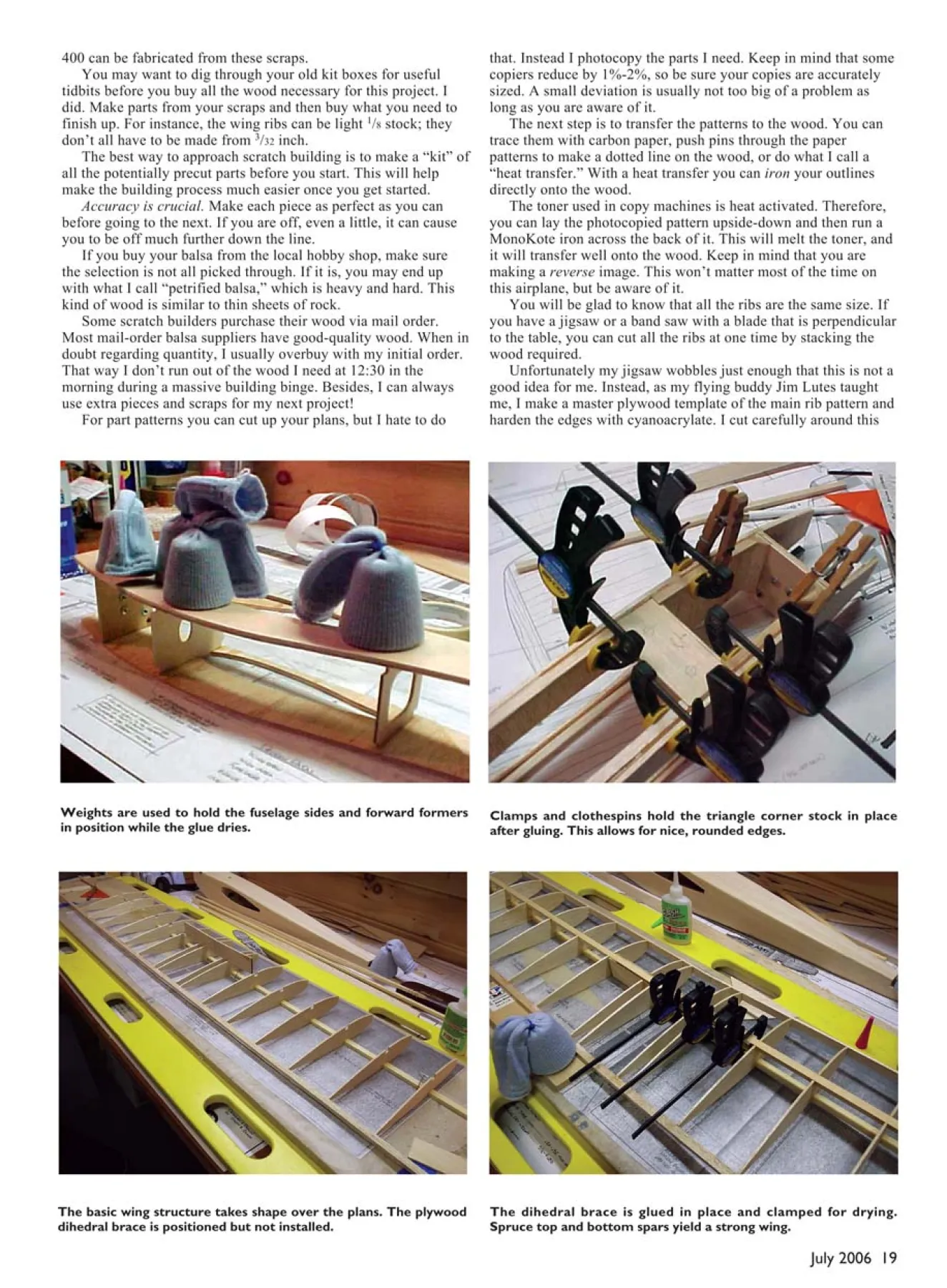
The completed fuselage crutch assembly shows the simplicity of
the structure’s design. This is a quick build.
such as myself, get Indianapolis 500 “race fever” each year. It is
similar to the “flying fever” most modelers get in the spring. The
Indy 400 name was inspired by the speed, excitement, and color
that surround this great auto-racing event. I often use the eyecatching
paint/color schemes of the Indy-style racecars for ideas
for color/trim schemes on my latest models. The other part of the
name came from the fact that the design has nearly 400 square
inches of wing area.
When I start this airplane at the flying field, sometimes I
swear I can hear a voice in the distance say, “Gentlemen, start
your engines!”
The Indy 400 was designed to do several things, the first of
which was to be a wonderful way to pass many lunch hours at
work. As drafting supervisor of the company I worked for at the
time, you would think the last thing I would have wanted to do at
lunch was draw; however, this project became a great mental
escape for me during the day. The hardest part was getting my
mind back on work when lunch was over!
My second goal was to create a small airplane that did not act
like a “little” airplane. This model handles very well. It flies like
it is on rails, even in windy conditions. It is aerobatic yet easy to
take off and land. After you are comfortable with the Indy 400,
control responses can be set to higher throws. At this point the
Indy 400 will be a sight to watch! The exclamation “Wahoo!”
comes to mind.
Third, I wanted to keep this little beast inexpensive. There are
many strong .25-size engines out there for not too much money. I
had used the K&B Sportster .28 on my last version, with good
power and reliability. On this model I chose a new O.S. .25 FX. I
liked the rear-mounted needle valve and had heard good things
about this engine.
The inside of the Indy 400 was designed with standard-size
servos and a flat 500 mAh battery pack in mind. There is really
only one way to install the radio gear since the airplane was
basically designed around it.
Don’t worry, though; it is not as tightly packed as it looks.
Your fingers will fit and installation is straightforward if you
follow the plans. You can install the servos in a 2 x 2
arrangement or a 3 x 1 arrangement, as I’ve done with this
specific model.
CONSTRUCTION
A materials list of the balsa, plywood, and spruce items you
will need is included elsewhere in this article. However, if you
are like me you have probably saved many odd-size sheets, drops,
and scraps from other scratch-building projects and kits
throughout the years. Many of the parts necessary for the Indy
Photos by the author
Indy 400 Materials List
• Reliable .25-size engine
• Suitable engine mount
• Aluminum landing gear with 9- to 10-inch spread
• 21/4-inch main wheels
• 1-inch tail-wheel assembly
• 4-ounce Sullivan Slant Type Flextank
• 11/2-inch spinner
• Sig canopy (WC-807)
• Control horns/pushrods
• 17 hinges
• Aileron torque-rod assembly
• Heat-shrinkable covering material
• Four pieces of 1/16 x 4 x 36 balsa sheet (fuselage)
• Three pieces of 3/32 x 4 x 36 balsa sheet (ribs)
• Four pieces of 1/8 x 4 x 36 balsa sheet (fuselage/miscellaneous)
• One piece of 1/4 x 4 x 36 balsa sheet (stabilizer and rudder)
• Two 1/2 x 1/2 x 36 balsa sticks (shaped to LE)
• Three 1/16 x 1/4 x 36 balsa sticks (capstrips)
• Two pieces of 1/4 x 11/2 x 36 aileron stock
• Two 1/4 x 3/8 x 36 balsa sticks (TE)
• Two 1/8 x 1/2 x 36 balsa sticks (wing front edge)
• Four 1/4 x 1/4 x 36 balsa sticks (stringers)
• One 1 x 2 x 36 balsa stick (wingtips and nose blocks)
• Two pieces of 1/2 x 1/2 x 36 balsa triangle stock
• Four 1/4 x 3/8 x 36 spruce spars
• One 1/8 and 1/4 plywood sheet
18 MODEL AVIATION
July 2006 19
The dihedral brace is glued in place and clamped for drying.
Spruce top and bottom spars yield a strong wing.
Weights are used to hold the fuselage sides and forward formers
in position while the glue dries.
Clamps and clothespins hold the triangle corner stock in place
after gluing. This allows for nice, rounded edges.
The basic wing structure takes shape over the plans. The plywood
dihedral brace is positioned but not installed.
400 can be fabricated from these scraps.
You may want to dig through your old kit boxes for useful
tidbits before you buy all the wood necessary for this project. I
did. Make parts from your scraps and then buy what you need to
finish up. For instance, the wing ribs can be light 1/8 stock; they
don’t all have to be made from 3/32 inch.
The best way to approach scratch building is to make a “kit” of
all the potentially precut parts before you start. This will help
make the building process much easier once you get started.
Accuracy is crucial. Make each piece as perfect as you can
before going to the next. If you are off, even a little, it can cause
you to be off much further down the line.
If you buy your balsa from the local hobby shop, make sure
the selection is not all picked through. If it is, you may end up
with what I call “petrified balsa,” which is heavy and hard. This
kind of wood is similar to thin sheets of rock.
Some scratch builders purchase their wood via mail order.
Most mail-order balsa suppliers have good-quality wood. When in
doubt regarding quantity, I usually overbuy with my initial order.
That way I don’t run out of the wood I need at 12:30 in the
morning during a massive building binge. Besides, I can always
use extra pieces and scraps for my next project!
For part patterns you can cut up your plans, but I hate to do
that. Instead I photocopy the parts I need. Keep in mind that some
copiers reduce by 1%-2%, so be sure your copies are accurately
sized. A small deviation is usually not too big of a problem as
long as you are aware of it.
The next step is to transfer the patterns to the wood. You can
trace them with carbon paper, push pins through the paper
patterns to make a dotted line on the wood, or do what I call a
“heat transfer.” With a heat transfer you can iron your outlines
directly onto the wood.
The toner used in copy machines is heat activated. Therefore,
you can lay the photocopied pattern upside-down and then run a
MonoKote iron across the back of it. This will melt the toner, and
it will transfer well onto the wood. Keep in mind that you are
making a reverse image. This won’t matter most of the time on
this airplane, but be aware of it.
You will be glad to know that all the ribs are the same size. If
you have a jigsaw or a band saw with a blade that is perpendicular
to the table, you can cut all the ribs at one time by stacking the
wood required.
Unfortunately my jigsaw wobbles just enough that this is not a
good idea for me. Instead, as my flying buddy Jim Lutes taught
me, I make a master plywood template of the main rib pattern and
harden the edges with cyanoacrylate. I cut carefully around this
Nothing is lovelier than a nicely built wood model, all sanded and
ready for finish.
The components are finished and ready for assembly. Notice that
the wing center-section is devoid of sheeting.
pattern with my X-Acto knife to make each rib.
Then I pin all the ribs together, in an even stack, and lightly
sand them to get them all as perfect and equal to each other as
possible. Don’t get too carried away with this sanding or you will
end up with a nice set of ribs that may fit some other model but
not the Indy 400!
Make sure all the spar notches line up perfectly. Also, make
sure your building surface is flat and not warped. The Indy 400
wing is extremely strong, even without covering. Therefore, it
would be difficult to remove a warp in the wing later by reversetwisting
it and reshrinking the covering to hold it in place.
Does that sound like something you’ve had to do in the past?
It does to me!
I have one last comment about building from scratch. If you
are interested in building this model but are reluctant because
you will have to make it from scratch, don’t be. In the scheme of
things, having to cut a few parts by hand adds little time to
building a model airplane.
Give this design a try; you will be pleased by how quickly it
goes together. And you will have the pleasure and pride of being
able to say “I built it from scratch.”
Wing: Place waxed paper over the wing plans. The bottom 1/4 x
3/8 spruce spar is pinned down to the plans. The rear strip is
oriented horizontally like the main 1/4 x 3/8 spruce spar.
All ribs except the two center ribs should be carefully aligned
with the plans and glued in at this point. Make sure that each is
90° perpendicular to the building table.
After the ribs are in place, add the rear 1/4 x 3/8 balsa strip.
You will have to support it off of the table. I used scraps of 3/8-
inch-thick material to do this. You can also add the 1/8 x 1/2 balsa
front secondary LE. The real LE is attached after the wing is
installed and glued in the fuselage. See the plans; it is a two-step
process.
The center ribs (two on each panel) will have to be cut down
slightly and attached after the dihedral braces are installed and
the wing panels are joined. Shear webs are not required on this
wing because of the “beef” in the spruce spars. If you wanted,
you could switch to balsa for the main spars and use shear webs.
Either method would be plenty strong for this design.
When both panels are complete, they can be joined using the
dihedral braces. These are going to be withstanding most of the
loading forces to which the wing is subjected. Therefore, use
good-grade plywood for these pieces. Light plywood might be
sufficient, but why take a chance?
Use 15- or 30-minute epoxy to join the plywood dihedral
braces to the spruce main spars. Take great care to make sure the
wing panels are aligned with each other and the amount of
dihedral shown on the plans is adhered to.
Type: RC sport
Wingspan: 42 inches
Engine: .20-.32
Flying weight: 3.5-4.0 pounds
Construction: Balsa and plywood
Covering/finish: Heat-shrink film of choice
The main purpose for installing dihedral on this wing is
aesthetics. To me, flat wings look like they are drooping. It is an
optical illusion, but a slight amount of dihedral cures that
perceived visual problem.
Once the wing panels are joined, add the remaining (four)
center ribs. They will have to be cut to fit the dihedral braces.
Gently true the wing with a long, flat sanding block in
preparation for sheeting the wing with 1/16 balsa.
Taper the front LE and the rear spar to receive the wing
sheeting. A little hand plane or a long sanding block works great
for this. When you begin sheeting the wing, start with the top
side first. Pin the panel being sheeted to the building board to
make sure the wing is flat and true. If it is not, you could build
twist into the wing while sheeting it.
I usually true the edge of my 1/16 balsa sheeting with a metal
straightedge. Then I coat the tops of the ribs with yellow
carpenter’s glue.
The front edge of the sheeting is attached to the 1/8 x 1/2 front
false LE strip with cyanoacrylate or carpenter’s glue. The
20 MODEL AVIATION
sheeting is then bent into place across the
ribs and pinned down. Glass Plus or
Windex sprayed onto the top of the
sheeting will allow it to bend easily
without cracking. I attach the rear of the
sheet to the ribs with thin cyanoacrylate.
Capstrips are attached using the same
technique when all sheeting is complete.
When the top of the wing is completed,
remove it from the building board and
sheet the bottom in the same manner as the
top. If there is any way you can pin down
the wing again (let one end hang off the
building board), this will help ensure that
there are no warps. The capstrips are
finally added along with the limited
center-section sheeting.
The center-section sheeting does not
cover the wing inside the fuselage. This
area is left open for radio installation. The
wing’s strength comes from the dual
dihedral braces and spruce spars. If you
have read ahead in these directions, you
will see that the spars in the wing will also
act as a surface for mounting servos.
Wingtips are your call. I like the looks
of the ones shown on the plans, and they
are easy to make. The original prototype
had flat tips (boring).
One of the guys at my field used curved
antivortex wingtips, as on the Sig Wonder
and the Craft-Air Viking. They looked
great, and he said they were not too much
more work. Do try to find some fairly light
wood for the wingtips or hollow them out
before attaching them. There is no sense in
adding too much extra weight for no gain in
performance or strength.
The ailerons are similar to those in
many kits you have probably made.
However, the torque rods are installed off
center! This is done because of the
aileron-servo location and arrangement
shown on the plans. As with the LE, the
aileron torque rods are not to be installed
until the wing has been permanently
mounted in the fuselage.
I have been asked why I did not make
the wing removable. I chose to
permanently mount it because it didn’t
need to be removable. This model fits
easily in trucks and small cars quite nicely.
If you think a permanently mounted
wing will add to the damage of a crashed
airplane, I disagree. If you crash a model
with a bolted-on wing, the damage can
still be extensive.
I crashed my first Indy 400 prototype
when I exceeded the “Legendary Speed of
Balsa” one fine summer afternoon,
because of battery failure. (Pilot error?
Impossible!) The model hit the ground
nose first. Repairs were no harder than if
the wing had been bolted down.
Set the wing aside in a location where
you and your family can admire it. It’s
time to get on with the rest of the craft.
Stabilizer and Fin: The Indy 400’s tail
feathers are straightforward. I made mine
from 1/4-inch-thick material but chose a
fairly light balsa for this purpose. The tail
feathers could be built up and sheeted or
just built up, but the plank pieces seemed
to work fine. There is plenty of room for
Robart-type hinges or cyanoacrylate
hinges. If you have a hinge preference, go
with it.
The hardest part about this portion of
assembly is the little fairing pieces that
form the fillet between the fin, stabilizer,
and fuselage body. I made a small Tshaped
part, in place of the stabilizer and
fin, from scrap 1/4 stock. I tack-glued the T
shape to the fuselage tail section in the
precise location. Then I tack-glued two
blank fillet pieces to the T shape.
Using the fuselage outline as a guide, I
carved and finish-sanded the fillet pieces.
Afterward I carefully separated the fillet
and T-shaped part, leaving two perfectly
shaped little fairings that were ready to be
glued in place once the stabilizer and fin
were permanently attached.
The tail-wheel assembly I used was the
Du-Bro unit for 40-size models. It fit the
bottom of the fuselage perfectly and was
easy to assemble and install. Where the
tail-wheel wire goes into the rudder, make
sure to drill it and then cyanoacrylate the
drill hole with the thin variety. That will
toughen this area. The control horn
sandwiches the wire between the two
control-horn assembly screws.
Fuselage: Try to find two pieces of
lightweight 1/8 balsa with a similar grain.
The goal is that they flex in a similarmanner when you bend them together to
form the rear of the fuselage. That will
help you keep this model straight!
You should build the fuselage on its
side, ensuring that each former is installed
square and perpendicular. Notice that the
vertical 1/16 sheeting stops at the back of
the engine mounting firewall.
Build over the plans to make sure
everything is straight! I also suggest
laying out the engine mount and drilling
the holes and installing the blind nuts. It’s
much easier now than later.
I made a template from the plans to cut
out the fuselage side. I carefully traced the
lines and scored the balsa below. Then I
came back and cut deeper, all the way
through the 1/8 balsa side. Using the first
side as a template I carefully cut out the
second. I lightly sanded the two while
pinned together to ensure that they were
exactly the same. I waited until the 1/16
balsa doubler was added to cut through for
the wing cutout so that it would be a
cleaner cut of both.
Install the landing-gear block and be
sure to add the triangle stock as shown.
Strength is necessary here. You will drill
and tap the mounting holes for the landing
gear after the fuselage is completed.
The fuselage stringers are a vital part
of this design. Yes, it’s an old-fashioned
construction technique, but it adds a great
deal of strength for a minimum weight
penalty. In addition, the stringers allow
you to round and radius the fuselage
during final sanding to make the Indy 400
even swoopier!
After you install the stringers, it’s time
to pull the sides together at the rear and join
them. You will need to slice an angle cut off
each lower stringer (see plans) so they meet
properly. For now just clamp or pin the ends
together.
Lay the fuselage on its side and measure
up from the table to find the centerline
measurement. Do the same after flipping the
fuselage over on the other side. If the
measurement is the same, it is probably
pretty straight. Don’t forget to eyeball it as
well, just to be sure.
Add the three spruce crossbraces shown
on the drawing for attaching the upper fuel
hatch and the lower radio hatch. You can
use plywood instead of spruce if you would
rather—just something that will hold screw
threads well. I cyanoacrylate-glued the
threaded holes after they were made, to
make the mount more durable for many
years of flying.
I constructed a framework for the lower
radio hatch from 1/8 balsa. Notice how it is
slightly curved; this is accomplished with
the special frame. Once the framework is
built, you will be able to glue an oversized
piece of 1/8-inch hatch material to it and it
will follow the curve of the fuselage just
right. Install the sheeting cross-grained.
Adding soft balsa blocks to the enginemount
area is a subjective process. What
and where depends on the engine you
select and the amount of rounding you
plan to do during final sanding.
I chose an O.S. .25 FX for the Indy
400, which meant that I had to
accommodate the rear-mounted needle
valve. Take some time in this area. A tidy
engine installation looks great. A sloppy
one does not and can spoil any airplane’s
appearance.
The top sheeting on the fuselage is
fairly straightforward. Pick a nice, light
piece of wood for this step. After you have
attached it you can trim it down and then
sand it even with the fuselage sides.
Notice the triangle stock at the front of the
top sheeting. This gives the sheeting a
stable place to be attached.
Add the plywood tail-wheel mount and
the plywood stabilizer-mount pieces. The
stabilizer mount should be installed level
with the fuselage top. Laying a ruler on
each area and then sighting from the rear
is helpful to determine when the two
surfaces are parallel.
The bottom sheeting is applied crossgrain.
This gives additional torsion
strength to the fuselage. The front area is
shown as light plywood. This area was
done with light plywood on the prototypes
and cross-grain balsa on other airplanes.
Both seemed fine. The Indy 400 in the
pictures was done with cross-grain balsa
pieces left overNow is a good time to try sliding the
wing into the fuselage. If it is tight or
binds you will need to enlarge the opening
carefully until it is just large enough for
the wing to pass through. Once in place
and centered, you can view it from the
back to see if it lines up with the fuselage
and tail feathers.
Pin the stabilizer in place and see how
everything looks. The straighter you build
this aircraft, the better it will fly. Take
extra care in sighting, measuring, and
aligning. I used a big aluminum
carpenter’s framing square to lay on top of
the fuselage to ensure that the wing was
exactly 90° to the fuselage. A little wood
typically needs to be removed from one
side or another of the fuselage wing cutout
to get the wing to lay correctly in relation
to the other parts of the model.
Radio Installation: It looks like a tight fit
in the radio compartment. It is, but there is
plenty of room if you arrange the servos as
shown on the plans and in the photos.
Keep in mind that you can use regular-size
radio gear. Lay out the components as
shown and you will be pleased with the
installation.
Notice how the rudder servo is
mounted higher than the elevator servo.
This was accomplished by adding another
piece of spruce servo rail on top of the
first one. It gives you the clearance you
need.
Again, notice the offset of the aileron
torque rods. This will show you exactly
which servo goes in this location. I used a
standard flat-pack battery and placed it
under the fuel tank wrapped in a plastic
bag. You did remember to cut the little
pass-through hole in the front former,
right? This is where the battery lead passes
through.
Final Details: The canopy shown looks
great, but there’s nothing set in stone
about this size or shape. I like the one I got
from Sig, but you could choose another or
none at all.
The metal landing gear mounts in a
straightforward manner. You can use a
premade unit such as I did or save some
weight and construct a set from carbon
fiber or fiberglass.
I highly recommend a tail wheel. You
could try only a skid if you fly strictly
from grass, but it would limit your groundcontrol
abilities. If you are flying from
pavement, a tail wheel is a must.
Covering: I used UltraCote on the model
presented here, but any covering will
work. The structure underneath does not
rely on the covering for strength, so have
fun. You probably have enough left over
from previous projects to cover the Indy
400.
Have fun with color too! I used neon
on the wings. I can get an extra flight or
two in at dusk with these colors. You
can’t beat that! In my experience
UltraCote-brand neon colors fade the
least, but they all fade a wee bit in time.
The checkerboard tail is indeed a
“signature look” for this model. You
don’t have to do the checkerboard pattern,
but I swear it will make the model fly a
bit faster!
I covered the entire rudder and fin
with white and then carefully cut out
black squares of trim-sheet material. For
the layout I ruled a 1 x 1-inch grid on the
fin and rudder with a fine-tip grease
pencil. The grid came off easily with
window cleaner when complete. Since it
is an Indy racing theme, a few neat racing
stickers look right if you are so inclined,
but make sure they are fuelproof!
I enlarged the “Indy 400” logo from
the plans to 101/2 inches long. Then I
taped it to a black MonoKote trim sheet
and carefully cut out the letters.
I used masking tape to lift all those
letters at once and applied them to a white
MonoKote trim sheet. I cut around the
letters, allowing roughly 1/8 inch of white
to show as a border. After that was
completed I lifted the logo again using a
long strip of masking tape and was able to
apply it to the wing. This method works
great and looks great.
Flying: This is the part you have been
waiting for!
Balance the aircraft. Mine
Edition: Model Aviation - 2006/07
Page Numbers: 17,18,19,20,21,22,23,24
Edition: Model Aviation - 2006/07
Page Numbers: 17,18,19,20,21,22,23,24
July 2006 17
THE INDY 400 represents an evolution of a 20- to 25-size
prototype I originally designed several years ago. Using many of
the design articles and principles I had seen in Radio Control
Modeler magazine throughout the years, I came up with an easybuilding
design I felt would fly quite well with a .20-.25 power
plant.
My goal in taking this step, in creating the final Indy 400, was
primarily to improve the overall aesthetics, weight, and
aerodynamics of the aircraft. The final version of the model is a
much sleeker, more swoopy and racy version of my original
design. It’s cool-lookin’!
The new version has benefited from my lessening the overall
weight, and its sleekness has increased the aircraft’s top speed.
Because of its reasonable size you will always have room in your
car to take the Indy 400 to the flying field. It is such a good allaround,
fun-to-fly model that it might become one of your
favorites to grab each time you head out.
Several local pilots are currently flying this design or the
earlier version. They encouraged me to do this construction article
because they enjoy the airplane so much. The Indy 400 has
become one of their favorite airplanes.
Why the “Indy 400” name? Many residents of Central Indiana,
The famed Indianapolis Motor Speedway is the backdrop for this
photo, and it was the inspiration for this sporty design.
by Scott Black
A compact and agile RC
sport aircraft for those on the go
From any angle this is a sleek, fast-looking model. It’s right at
home in Indy! It’s simple to build and rugged.
The completed fuselage crutch assembly shows the simplicity of
the structure’s design. This is a quick build.
such as myself, get Indianapolis 500 “race fever” each year. It is
similar to the “flying fever” most modelers get in the spring. The
Indy 400 name was inspired by the speed, excitement, and color
that surround this great auto-racing event. I often use the eyecatching
paint/color schemes of the Indy-style racecars for ideas
for color/trim schemes on my latest models. The other part of the
name came from the fact that the design has nearly 400 square
inches of wing area.
When I start this airplane at the flying field, sometimes I
swear I can hear a voice in the distance say, “Gentlemen, start
your engines!”
The Indy 400 was designed to do several things, the first of
which was to be a wonderful way to pass many lunch hours at
work. As drafting supervisor of the company I worked for at the
time, you would think the last thing I would have wanted to do at
lunch was draw; however, this project became a great mental
escape for me during the day. The hardest part was getting my
mind back on work when lunch was over!
My second goal was to create a small airplane that did not act
like a “little” airplane. This model handles very well. It flies like
it is on rails, even in windy conditions. It is aerobatic yet easy to
take off and land. After you are comfortable with the Indy 400,
control responses can be set to higher throws. At this point the
Indy 400 will be a sight to watch! The exclamation “Wahoo!”
comes to mind.
Third, I wanted to keep this little beast inexpensive. There are
many strong .25-size engines out there for not too much money. I
had used the K&B Sportster .28 on my last version, with good
power and reliability. On this model I chose a new O.S. .25 FX. I
liked the rear-mounted needle valve and had heard good things
about this engine.
The inside of the Indy 400 was designed with standard-size
servos and a flat 500 mAh battery pack in mind. There is really
only one way to install the radio gear since the airplane was
basically designed around it.
Don’t worry, though; it is not as tightly packed as it looks.
Your fingers will fit and installation is straightforward if you
follow the plans. You can install the servos in a 2 x 2
arrangement or a 3 x 1 arrangement, as I’ve done with this
specific model.
CONSTRUCTION
A materials list of the balsa, plywood, and spruce items you
will need is included elsewhere in this article. However, if you
are like me you have probably saved many odd-size sheets, drops,
and scraps from other scratch-building projects and kits
throughout the years. Many of the parts necessary for the Indy
Photos by the author
Indy 400 Materials List
• Reliable .25-size engine
• Suitable engine mount
• Aluminum landing gear with 9- to 10-inch spread
• 21/4-inch main wheels
• 1-inch tail-wheel assembly
• 4-ounce Sullivan Slant Type Flextank
• 11/2-inch spinner
• Sig canopy (WC-807)
• Control horns/pushrods
• 17 hinges
• Aileron torque-rod assembly
• Heat-shrinkable covering material
• Four pieces of 1/16 x 4 x 36 balsa sheet (fuselage)
• Three pieces of 3/32 x 4 x 36 balsa sheet (ribs)
• Four pieces of 1/8 x 4 x 36 balsa sheet (fuselage/miscellaneous)
• One piece of 1/4 x 4 x 36 balsa sheet (stabilizer and rudder)
• Two 1/2 x 1/2 x 36 balsa sticks (shaped to LE)
• Three 1/16 x 1/4 x 36 balsa sticks (capstrips)
• Two pieces of 1/4 x 11/2 x 36 aileron stock
• Two 1/4 x 3/8 x 36 balsa sticks (TE)
• Two 1/8 x 1/2 x 36 balsa sticks (wing front edge)
• Four 1/4 x 1/4 x 36 balsa sticks (stringers)
• One 1 x 2 x 36 balsa stick (wingtips and nose blocks)
• Two pieces of 1/2 x 1/2 x 36 balsa triangle stock
• Four 1/4 x 3/8 x 36 spruce spars
• One 1/8 and 1/4 plywood sheet
18 MODEL AVIATION
July 2006 19
The dihedral brace is glued in place and clamped for drying.
Spruce top and bottom spars yield a strong wing.
Weights are used to hold the fuselage sides and forward formers
in position while the glue dries.
Clamps and clothespins hold the triangle corner stock in place
after gluing. This allows for nice, rounded edges.
The basic wing structure takes shape over the plans. The plywood
dihedral brace is positioned but not installed.
400 can be fabricated from these scraps.
You may want to dig through your old kit boxes for useful
tidbits before you buy all the wood necessary for this project. I
did. Make parts from your scraps and then buy what you need to
finish up. For instance, the wing ribs can be light 1/8 stock; they
don’t all have to be made from 3/32 inch.
The best way to approach scratch building is to make a “kit” of
all the potentially precut parts before you start. This will help
make the building process much easier once you get started.
Accuracy is crucial. Make each piece as perfect as you can
before going to the next. If you are off, even a little, it can cause
you to be off much further down the line.
If you buy your balsa from the local hobby shop, make sure
the selection is not all picked through. If it is, you may end up
with what I call “petrified balsa,” which is heavy and hard. This
kind of wood is similar to thin sheets of rock.
Some scratch builders purchase their wood via mail order.
Most mail-order balsa suppliers have good-quality wood. When in
doubt regarding quantity, I usually overbuy with my initial order.
That way I don’t run out of the wood I need at 12:30 in the
morning during a massive building binge. Besides, I can always
use extra pieces and scraps for my next project!
For part patterns you can cut up your plans, but I hate to do
that. Instead I photocopy the parts I need. Keep in mind that some
copiers reduce by 1%-2%, so be sure your copies are accurately
sized. A small deviation is usually not too big of a problem as
long as you are aware of it.
The next step is to transfer the patterns to the wood. You can
trace them with carbon paper, push pins through the paper
patterns to make a dotted line on the wood, or do what I call a
“heat transfer.” With a heat transfer you can iron your outlines
directly onto the wood.
The toner used in copy machines is heat activated. Therefore,
you can lay the photocopied pattern upside-down and then run a
MonoKote iron across the back of it. This will melt the toner, and
it will transfer well onto the wood. Keep in mind that you are
making a reverse image. This won’t matter most of the time on
this airplane, but be aware of it.
You will be glad to know that all the ribs are the same size. If
you have a jigsaw or a band saw with a blade that is perpendicular
to the table, you can cut all the ribs at one time by stacking the
wood required.
Unfortunately my jigsaw wobbles just enough that this is not a
good idea for me. Instead, as my flying buddy Jim Lutes taught
me, I make a master plywood template of the main rib pattern and
harden the edges with cyanoacrylate. I cut carefully around this
Nothing is lovelier than a nicely built wood model, all sanded and
ready for finish.
The components are finished and ready for assembly. Notice that
the wing center-section is devoid of sheeting.
pattern with my X-Acto knife to make each rib.
Then I pin all the ribs together, in an even stack, and lightly
sand them to get them all as perfect and equal to each other as
possible. Don’t get too carried away with this sanding or you will
end up with a nice set of ribs that may fit some other model but
not the Indy 400!
Make sure all the spar notches line up perfectly. Also, make
sure your building surface is flat and not warped. The Indy 400
wing is extremely strong, even without covering. Therefore, it
would be difficult to remove a warp in the wing later by reversetwisting
it and reshrinking the covering to hold it in place.
Does that sound like something you’ve had to do in the past?
It does to me!
I have one last comment about building from scratch. If you
are interested in building this model but are reluctant because
you will have to make it from scratch, don’t be. In the scheme of
things, having to cut a few parts by hand adds little time to
building a model airplane.
Give this design a try; you will be pleased by how quickly it
goes together. And you will have the pleasure and pride of being
able to say “I built it from scratch.”
Wing: Place waxed paper over the wing plans. The bottom 1/4 x
3/8 spruce spar is pinned down to the plans. The rear strip is
oriented horizontally like the main 1/4 x 3/8 spruce spar.
All ribs except the two center ribs should be carefully aligned
with the plans and glued in at this point. Make sure that each is
90° perpendicular to the building table.
After the ribs are in place, add the rear 1/4 x 3/8 balsa strip.
You will have to support it off of the table. I used scraps of 3/8-
inch-thick material to do this. You can also add the 1/8 x 1/2 balsa
front secondary LE. The real LE is attached after the wing is
installed and glued in the fuselage. See the plans; it is a two-step
process.
The center ribs (two on each panel) will have to be cut down
slightly and attached after the dihedral braces are installed and
the wing panels are joined. Shear webs are not required on this
wing because of the “beef” in the spruce spars. If you wanted,
you could switch to balsa for the main spars and use shear webs.
Either method would be plenty strong for this design.
When both panels are complete, they can be joined using the
dihedral braces. These are going to be withstanding most of the
loading forces to which the wing is subjected. Therefore, use
good-grade plywood for these pieces. Light plywood might be
sufficient, but why take a chance?
Use 15- or 30-minute epoxy to join the plywood dihedral
braces to the spruce main spars. Take great care to make sure the
wing panels are aligned with each other and the amount of
dihedral shown on the plans is adhered to.
Type: RC sport
Wingspan: 42 inches
Engine: .20-.32
Flying weight: 3.5-4.0 pounds
Construction: Balsa and plywood
Covering/finish: Heat-shrink film of choice
The main purpose for installing dihedral on this wing is
aesthetics. To me, flat wings look like they are drooping. It is an
optical illusion, but a slight amount of dihedral cures that
perceived visual problem.
Once the wing panels are joined, add the remaining (four)
center ribs. They will have to be cut to fit the dihedral braces.
Gently true the wing with a long, flat sanding block in
preparation for sheeting the wing with 1/16 balsa.
Taper the front LE and the rear spar to receive the wing
sheeting. A little hand plane or a long sanding block works great
for this. When you begin sheeting the wing, start with the top
side first. Pin the panel being sheeted to the building board to
make sure the wing is flat and true. If it is not, you could build
twist into the wing while sheeting it.
I usually true the edge of my 1/16 balsa sheeting with a metal
straightedge. Then I coat the tops of the ribs with yellow
carpenter’s glue.
The front edge of the sheeting is attached to the 1/8 x 1/2 front
false LE strip with cyanoacrylate or carpenter’s glue. The
20 MODEL AVIATION
sheeting is then bent into place across the
ribs and pinned down. Glass Plus or
Windex sprayed onto the top of the
sheeting will allow it to bend easily
without cracking. I attach the rear of the
sheet to the ribs with thin cyanoacrylate.
Capstrips are attached using the same
technique when all sheeting is complete.
When the top of the wing is completed,
remove it from the building board and
sheet the bottom in the same manner as the
top. If there is any way you can pin down
the wing again (let one end hang off the
building board), this will help ensure that
there are no warps. The capstrips are
finally added along with the limited
center-section sheeting.
The center-section sheeting does not
cover the wing inside the fuselage. This
area is left open for radio installation. The
wing’s strength comes from the dual
dihedral braces and spruce spars. If you
have read ahead in these directions, you
will see that the spars in the wing will also
act as a surface for mounting servos.
Wingtips are your call. I like the looks
of the ones shown on the plans, and they
are easy to make. The original prototype
had flat tips (boring).
One of the guys at my field used curved
antivortex wingtips, as on the Sig Wonder
and the Craft-Air Viking. They looked
great, and he said they were not too much
more work. Do try to find some fairly light
wood for the wingtips or hollow them out
before attaching them. There is no sense in
adding too much extra weight for no gain in
performance or strength.
The ailerons are similar to those in
many kits you have probably made.
However, the torque rods are installed off
center! This is done because of the
aileron-servo location and arrangement
shown on the plans. As with the LE, the
aileron torque rods are not to be installed
until the wing has been permanently
mounted in the fuselage.
I have been asked why I did not make
the wing removable. I chose to
permanently mount it because it didn’t
need to be removable. This model fits
easily in trucks and small cars quite nicely.
If you think a permanently mounted
wing will add to the damage of a crashed
airplane, I disagree. If you crash a model
with a bolted-on wing, the damage can
still be extensive.
I crashed my first Indy 400 prototype
when I exceeded the “Legendary Speed of
Balsa” one fine summer afternoon,
because of battery failure. (Pilot error?
Impossible!) The model hit the ground
nose first. Repairs were no harder than if
the wing had been bolted down.
Set the wing aside in a location where
you and your family can admire it. It’s
time to get on with the rest of the craft.
Stabilizer and Fin: The Indy 400’s tail
feathers are straightforward. I made mine
from 1/4-inch-thick material but chose a
fairly light balsa for this purpose. The tail
feathers could be built up and sheeted or
just built up, but the plank pieces seemed
to work fine. There is plenty of room for
Robart-type hinges or cyanoacrylate
hinges. If you have a hinge preference, go
with it.
The hardest part about this portion of
assembly is the little fairing pieces that
form the fillet between the fin, stabilizer,
and fuselage body. I made a small Tshaped
part, in place of the stabilizer and
fin, from scrap 1/4 stock. I tack-glued the T
shape to the fuselage tail section in the
precise location. Then I tack-glued two
blank fillet pieces to the T shape.
Using the fuselage outline as a guide, I
carved and finish-sanded the fillet pieces.
Afterward I carefully separated the fillet
and T-shaped part, leaving two perfectly
shaped little fairings that were ready to be
glued in place once the stabilizer and fin
were permanently attached.
The tail-wheel assembly I used was the
Du-Bro unit for 40-size models. It fit the
bottom of the fuselage perfectly and was
easy to assemble and install. Where the
tail-wheel wire goes into the rudder, make
sure to drill it and then cyanoacrylate the
drill hole with the thin variety. That will
toughen this area. The control horn
sandwiches the wire between the two
control-horn assembly screws.
Fuselage: Try to find two pieces of
lightweight 1/8 balsa with a similar grain.
The goal is that they flex in a similarmanner when you bend them together to
form the rear of the fuselage. That will
help you keep this model straight!
You should build the fuselage on its
side, ensuring that each former is installed
square and perpendicular. Notice that the
vertical 1/16 sheeting stops at the back of
the engine mounting firewall.
Build over the plans to make sure
everything is straight! I also suggest
laying out the engine mount and drilling
the holes and installing the blind nuts. It’s
much easier now than later.
I made a template from the plans to cut
out the fuselage side. I carefully traced the
lines and scored the balsa below. Then I
came back and cut deeper, all the way
through the 1/8 balsa side. Using the first
side as a template I carefully cut out the
second. I lightly sanded the two while
pinned together to ensure that they were
exactly the same. I waited until the 1/16
balsa doubler was added to cut through for
the wing cutout so that it would be a
cleaner cut of both.
Install the landing-gear block and be
sure to add the triangle stock as shown.
Strength is necessary here. You will drill
and tap the mounting holes for the landing
gear after the fuselage is completed.
The fuselage stringers are a vital part
of this design. Yes, it’s an old-fashioned
construction technique, but it adds a great
deal of strength for a minimum weight
penalty. In addition, the stringers allow
you to round and radius the fuselage
during final sanding to make the Indy 400
even swoopier!
After you install the stringers, it’s time
to pull the sides together at the rear and join
them. You will need to slice an angle cut off
each lower stringer (see plans) so they meet
properly. For now just clamp or pin the ends
together.
Lay the fuselage on its side and measure
up from the table to find the centerline
measurement. Do the same after flipping the
fuselage over on the other side. If the
measurement is the same, it is probably
pretty straight. Don’t forget to eyeball it as
well, just to be sure.
Add the three spruce crossbraces shown
on the drawing for attaching the upper fuel
hatch and the lower radio hatch. You can
use plywood instead of spruce if you would
rather—just something that will hold screw
threads well. I cyanoacrylate-glued the
threaded holes after they were made, to
make the mount more durable for many
years of flying.
I constructed a framework for the lower
radio hatch from 1/8 balsa. Notice how it is
slightly curved; this is accomplished with
the special frame. Once the framework is
built, you will be able to glue an oversized
piece of 1/8-inch hatch material to it and it
will follow the curve of the fuselage just
right. Install the sheeting cross-grained.
Adding soft balsa blocks to the enginemount
area is a subjective process. What
and where depends on the engine you
select and the amount of rounding you
plan to do during final sanding.
I chose an O.S. .25 FX for the Indy
400, which meant that I had to
accommodate the rear-mounted needle
valve. Take some time in this area. A tidy
engine installation looks great. A sloppy
one does not and can spoil any airplane’s
appearance.
The top sheeting on the fuselage is
fairly straightforward. Pick a nice, light
piece of wood for this step. After you have
attached it you can trim it down and then
sand it even with the fuselage sides.
Notice the triangle stock at the front of the
top sheeting. This gives the sheeting a
stable place to be attached.
Add the plywood tail-wheel mount and
the plywood stabilizer-mount pieces. The
stabilizer mount should be installed level
with the fuselage top. Laying a ruler on
each area and then sighting from the rear
is helpful to determine when the two
surfaces are parallel.
The bottom sheeting is applied crossgrain.
This gives additional torsion
strength to the fuselage. The front area is
shown as light plywood. This area was
done with light plywood on the prototypes
and cross-grain balsa on other airplanes.
Both seemed fine. The Indy 400 in the
pictures was done with cross-grain balsa
pieces left overNow is a good time to try sliding the
wing into the fuselage. If it is tight or
binds you will need to enlarge the opening
carefully until it is just large enough for
the wing to pass through. Once in place
and centered, you can view it from the
back to see if it lines up with the fuselage
and tail feathers.
Pin the stabilizer in place and see how
everything looks. The straighter you build
this aircraft, the better it will fly. Take
extra care in sighting, measuring, and
aligning. I used a big aluminum
carpenter’s framing square to lay on top of
the fuselage to ensure that the wing was
exactly 90° to the fuselage. A little wood
typically needs to be removed from one
side or another of the fuselage wing cutout
to get the wing to lay correctly in relation
to the other parts of the model.
Radio Installation: It looks like a tight fit
in the radio compartment. It is, but there is
plenty of room if you arrange the servos as
shown on the plans and in the photos.
Keep in mind that you can use regular-size
radio gear. Lay out the components as
shown and you will be pleased with the
installation.
Notice how the rudder servo is
mounted higher than the elevator servo.
This was accomplished by adding another
piece of spruce servo rail on top of the
first one. It gives you the clearance you
need.
Again, notice the offset of the aileron
torque rods. This will show you exactly
which servo goes in this location. I used a
standard flat-pack battery and placed it
under the fuel tank wrapped in a plastic
bag. You did remember to cut the little
pass-through hole in the front former,
right? This is where the battery lead passes
through.
Final Details: The canopy shown looks
great, but there’s nothing set in stone
about this size or shape. I like the one I got
from Sig, but you could choose another or
none at all.
The metal landing gear mounts in a
straightforward manner. You can use a
premade unit such as I did or save some
weight and construct a set from carbon
fiber or fiberglass.
I highly recommend a tail wheel. You
could try only a skid if you fly strictly
from grass, but it would limit your groundcontrol
abilities. If you are flying from
pavement, a tail wheel is a must.
Covering: I used UltraCote on the model
presented here, but any covering will
work. The structure underneath does not
rely on the covering for strength, so have
fun. You probably have enough left over
from previous projects to cover the Indy
400.
Have fun with color too! I used neon
on the wings. I can get an extra flight or
two in at dusk with these colors. You
can’t beat that! In my experience
UltraCote-brand neon colors fade the
least, but they all fade a wee bit in time.
The checkerboard tail is indeed a
“signature look” for this model. You
don’t have to do the checkerboard pattern,
but I swear it will make the model fly a
bit faster!
I covered the entire rudder and fin
with white and then carefully cut out
black squares of trim-sheet material. For
the layout I ruled a 1 x 1-inch grid on the
fin and rudder with a fine-tip grease
pencil. The grid came off easily with
window cleaner when complete. Since it
is an Indy racing theme, a few neat racing
stickers look right if you are so inclined,
but make sure they are fuelproof!
I enlarged the “Indy 400” logo from
the plans to 101/2 inches long. Then I
taped it to a black MonoKote trim sheet
and carefully cut out the letters.
I used masking tape to lift all those
letters at once and applied them to a white
MonoKote trim sheet. I cut around the
letters, allowing roughly 1/8 inch of white
to show as a border. After that was
completed I lifted the logo again using a
long strip of masking tape and was able to
apply it to the wing. This method works
great and looks great.
Flying: This is the part you have been
waiting for!
Balance the aircraft. Mine
Edition: Model Aviation - 2006/07
Page Numbers: 17,18,19,20,21,22,23,24
July 2006 17
THE INDY 400 represents an evolution of a 20- to 25-size
prototype I originally designed several years ago. Using many of
the design articles and principles I had seen in Radio Control
Modeler magazine throughout the years, I came up with an easybuilding
design I felt would fly quite well with a .20-.25 power
plant.
My goal in taking this step, in creating the final Indy 400, was
primarily to improve the overall aesthetics, weight, and
aerodynamics of the aircraft. The final version of the model is a
much sleeker, more swoopy and racy version of my original
design. It’s cool-lookin’!
The new version has benefited from my lessening the overall
weight, and its sleekness has increased the aircraft’s top speed.
Because of its reasonable size you will always have room in your
car to take the Indy 400 to the flying field. It is such a good allaround,
fun-to-fly model that it might become one of your
favorites to grab each time you head out.
Several local pilots are currently flying this design or the
earlier version. They encouraged me to do this construction article
because they enjoy the airplane so much. The Indy 400 has
become one of their favorite airplanes.
Why the “Indy 400” name? Many residents of Central Indiana,
The famed Indianapolis Motor Speedway is the backdrop for this
photo, and it was the inspiration for this sporty design.
by Scott Black
A compact and agile RC
sport aircraft for those on the go
From any angle this is a sleek, fast-looking model. It’s right at
home in Indy! It’s simple to build and rugged.
The completed fuselage crutch assembly shows the simplicity of
the structure’s design. This is a quick build.
such as myself, get Indianapolis 500 “race fever” each year. It is
similar to the “flying fever” most modelers get in the spring. The
Indy 400 name was inspired by the speed, excitement, and color
that surround this great auto-racing event. I often use the eyecatching
paint/color schemes of the Indy-style racecars for ideas
for color/trim schemes on my latest models. The other part of the
name came from the fact that the design has nearly 400 square
inches of wing area.
When I start this airplane at the flying field, sometimes I
swear I can hear a voice in the distance say, “Gentlemen, start
your engines!”
The Indy 400 was designed to do several things, the first of
which was to be a wonderful way to pass many lunch hours at
work. As drafting supervisor of the company I worked for at the
time, you would think the last thing I would have wanted to do at
lunch was draw; however, this project became a great mental
escape for me during the day. The hardest part was getting my
mind back on work when lunch was over!
My second goal was to create a small airplane that did not act
like a “little” airplane. This model handles very well. It flies like
it is on rails, even in windy conditions. It is aerobatic yet easy to
take off and land. After you are comfortable with the Indy 400,
control responses can be set to higher throws. At this point the
Indy 400 will be a sight to watch! The exclamation “Wahoo!”
comes to mind.
Third, I wanted to keep this little beast inexpensive. There are
many strong .25-size engines out there for not too much money. I
had used the K&B Sportster .28 on my last version, with good
power and reliability. On this model I chose a new O.S. .25 FX. I
liked the rear-mounted needle valve and had heard good things
about this engine.
The inside of the Indy 400 was designed with standard-size
servos and a flat 500 mAh battery pack in mind. There is really
only one way to install the radio gear since the airplane was
basically designed around it.
Don’t worry, though; it is not as tightly packed as it looks.
Your fingers will fit and installation is straightforward if you
follow the plans. You can install the servos in a 2 x 2
arrangement or a 3 x 1 arrangement, as I’ve done with this
specific model.
CONSTRUCTION
A materials list of the balsa, plywood, and spruce items you
will need is included elsewhere in this article. However, if you
are like me you have probably saved many odd-size sheets, drops,
and scraps from other scratch-building projects and kits
throughout the years. Many of the parts necessary for the Indy
Photos by the author
Indy 400 Materials List
• Reliable .25-size engine
• Suitable engine mount
• Aluminum landing gear with 9- to 10-inch spread
• 21/4-inch main wheels
• 1-inch tail-wheel assembly
• 4-ounce Sullivan Slant Type Flextank
• 11/2-inch spinner
• Sig canopy (WC-807)
• Control horns/pushrods
• 17 hinges
• Aileron torque-rod assembly
• Heat-shrinkable covering material
• Four pieces of 1/16 x 4 x 36 balsa sheet (fuselage)
• Three pieces of 3/32 x 4 x 36 balsa sheet (ribs)
• Four pieces of 1/8 x 4 x 36 balsa sheet (fuselage/miscellaneous)
• One piece of 1/4 x 4 x 36 balsa sheet (stabilizer and rudder)
• Two 1/2 x 1/2 x 36 balsa sticks (shaped to LE)
• Three 1/16 x 1/4 x 36 balsa sticks (capstrips)
• Two pieces of 1/4 x 11/2 x 36 aileron stock
• Two 1/4 x 3/8 x 36 balsa sticks (TE)
• Two 1/8 x 1/2 x 36 balsa sticks (wing front edge)
• Four 1/4 x 1/4 x 36 balsa sticks (stringers)
• One 1 x 2 x 36 balsa stick (wingtips and nose blocks)
• Two pieces of 1/2 x 1/2 x 36 balsa triangle stock
• Four 1/4 x 3/8 x 36 spruce spars
• One 1/8 and 1/4 plywood sheet
18 MODEL AVIATION
July 2006 19
The dihedral brace is glued in place and clamped for drying.
Spruce top and bottom spars yield a strong wing.
Weights are used to hold the fuselage sides and forward formers
in position while the glue dries.
Clamps and clothespins hold the triangle corner stock in place
after gluing. This allows for nice, rounded edges.
The basic wing structure takes shape over the plans. The plywood
dihedral brace is positioned but not installed.
400 can be fabricated from these scraps.
You may want to dig through your old kit boxes for useful
tidbits before you buy all the wood necessary for this project. I
did. Make parts from your scraps and then buy what you need to
finish up. For instance, the wing ribs can be light 1/8 stock; they
don’t all have to be made from 3/32 inch.
The best way to approach scratch building is to make a “kit” of
all the potentially precut parts before you start. This will help
make the building process much easier once you get started.
Accuracy is crucial. Make each piece as perfect as you can
before going to the next. If you are off, even a little, it can cause
you to be off much further down the line.
If you buy your balsa from the local hobby shop, make sure
the selection is not all picked through. If it is, you may end up
with what I call “petrified balsa,” which is heavy and hard. This
kind of wood is similar to thin sheets of rock.
Some scratch builders purchase their wood via mail order.
Most mail-order balsa suppliers have good-quality wood. When in
doubt regarding quantity, I usually overbuy with my initial order.
That way I don’t run out of the wood I need at 12:30 in the
morning during a massive building binge. Besides, I can always
use extra pieces and scraps for my next project!
For part patterns you can cut up your plans, but I hate to do
that. Instead I photocopy the parts I need. Keep in mind that some
copiers reduce by 1%-2%, so be sure your copies are accurately
sized. A small deviation is usually not too big of a problem as
long as you are aware of it.
The next step is to transfer the patterns to the wood. You can
trace them with carbon paper, push pins through the paper
patterns to make a dotted line on the wood, or do what I call a
“heat transfer.” With a heat transfer you can iron your outlines
directly onto the wood.
The toner used in copy machines is heat activated. Therefore,
you can lay the photocopied pattern upside-down and then run a
MonoKote iron across the back of it. This will melt the toner, and
it will transfer well onto the wood. Keep in mind that you are
making a reverse image. This won’t matter most of the time on
this airplane, but be aware of it.
You will be glad to know that all the ribs are the same size. If
you have a jigsaw or a band saw with a blade that is perpendicular
to the table, you can cut all the ribs at one time by stacking the
wood required.
Unfortunately my jigsaw wobbles just enough that this is not a
good idea for me. Instead, as my flying buddy Jim Lutes taught
me, I make a master plywood template of the main rib pattern and
harden the edges with cyanoacrylate. I cut carefully around this
Nothing is lovelier than a nicely built wood model, all sanded and
ready for finish.
The components are finished and ready for assembly. Notice that
the wing center-section is devoid of sheeting.
pattern with my X-Acto knife to make each rib.
Then I pin all the ribs together, in an even stack, and lightly
sand them to get them all as perfect and equal to each other as
possible. Don’t get too carried away with this sanding or you will
end up with a nice set of ribs that may fit some other model but
not the Indy 400!
Make sure all the spar notches line up perfectly. Also, make
sure your building surface is flat and not warped. The Indy 400
wing is extremely strong, even without covering. Therefore, it
would be difficult to remove a warp in the wing later by reversetwisting
it and reshrinking the covering to hold it in place.
Does that sound like something you’ve had to do in the past?
It does to me!
I have one last comment about building from scratch. If you
are interested in building this model but are reluctant because
you will have to make it from scratch, don’t be. In the scheme of
things, having to cut a few parts by hand adds little time to
building a model airplane.
Give this design a try; you will be pleased by how quickly it
goes together. And you will have the pleasure and pride of being
able to say “I built it from scratch.”
Wing: Place waxed paper over the wing plans. The bottom 1/4 x
3/8 spruce spar is pinned down to the plans. The rear strip is
oriented horizontally like the main 1/4 x 3/8 spruce spar.
All ribs except the two center ribs should be carefully aligned
with the plans and glued in at this point. Make sure that each is
90° perpendicular to the building table.
After the ribs are in place, add the rear 1/4 x 3/8 balsa strip.
You will have to support it off of the table. I used scraps of 3/8-
inch-thick material to do this. You can also add the 1/8 x 1/2 balsa
front secondary LE. The real LE is attached after the wing is
installed and glued in the fuselage. See the plans; it is a two-step
process.
The center ribs (two on each panel) will have to be cut down
slightly and attached after the dihedral braces are installed and
the wing panels are joined. Shear webs are not required on this
wing because of the “beef” in the spruce spars. If you wanted,
you could switch to balsa for the main spars and use shear webs.
Either method would be plenty strong for this design.
When both panels are complete, they can be joined using the
dihedral braces. These are going to be withstanding most of the
loading forces to which the wing is subjected. Therefore, use
good-grade plywood for these pieces. Light plywood might be
sufficient, but why take a chance?
Use 15- or 30-minute epoxy to join the plywood dihedral
braces to the spruce main spars. Take great care to make sure the
wing panels are aligned with each other and the amount of
dihedral shown on the plans is adhered to.
Type: RC sport
Wingspan: 42 inches
Engine: .20-.32
Flying weight: 3.5-4.0 pounds
Construction: Balsa and plywood
Covering/finish: Heat-shrink film of choice
The main purpose for installing dihedral on this wing is
aesthetics. To me, flat wings look like they are drooping. It is an
optical illusion, but a slight amount of dihedral cures that
perceived visual problem.
Once the wing panels are joined, add the remaining (four)
center ribs. They will have to be cut to fit the dihedral braces.
Gently true the wing with a long, flat sanding block in
preparation for sheeting the wing with 1/16 balsa.
Taper the front LE and the rear spar to receive the wing
sheeting. A little hand plane or a long sanding block works great
for this. When you begin sheeting the wing, start with the top
side first. Pin the panel being sheeted to the building board to
make sure the wing is flat and true. If it is not, you could build
twist into the wing while sheeting it.
I usually true the edge of my 1/16 balsa sheeting with a metal
straightedge. Then I coat the tops of the ribs with yellow
carpenter’s glue.
The front edge of the sheeting is attached to the 1/8 x 1/2 front
false LE strip with cyanoacrylate or carpenter’s glue. The
20 MODEL AVIATION
sheeting is then bent into place across the
ribs and pinned down. Glass Plus or
Windex sprayed onto the top of the
sheeting will allow it to bend easily
without cracking. I attach the rear of the
sheet to the ribs with thin cyanoacrylate.
Capstrips are attached using the same
technique when all sheeting is complete.
When the top of the wing is completed,
remove it from the building board and
sheet the bottom in the same manner as the
top. If there is any way you can pin down
the wing again (let one end hang off the
building board), this will help ensure that
there are no warps. The capstrips are
finally added along with the limited
center-section sheeting.
The center-section sheeting does not
cover the wing inside the fuselage. This
area is left open for radio installation. The
wing’s strength comes from the dual
dihedral braces and spruce spars. If you
have read ahead in these directions, you
will see that the spars in the wing will also
act as a surface for mounting servos.
Wingtips are your call. I like the looks
of the ones shown on the plans, and they
are easy to make. The original prototype
had flat tips (boring).
One of the guys at my field used curved
antivortex wingtips, as on the Sig Wonder
and the Craft-Air Viking. They looked
great, and he said they were not too much
more work. Do try to find some fairly light
wood for the wingtips or hollow them out
before attaching them. There is no sense in
adding too much extra weight for no gain in
performance or strength.
The ailerons are similar to those in
many kits you have probably made.
However, the torque rods are installed off
center! This is done because of the
aileron-servo location and arrangement
shown on the plans. As with the LE, the
aileron torque rods are not to be installed
until the wing has been permanently
mounted in the fuselage.
I have been asked why I did not make
the wing removable. I chose to
permanently mount it because it didn’t
need to be removable. This model fits
easily in trucks and small cars quite nicely.
If you think a permanently mounted
wing will add to the damage of a crashed
airplane, I disagree. If you crash a model
with a bolted-on wing, the damage can
still be extensive.
I crashed my first Indy 400 prototype
when I exceeded the “Legendary Speed of
Balsa” one fine summer afternoon,
because of battery failure. (Pilot error?
Impossible!) The model hit the ground
nose first. Repairs were no harder than if
the wing had been bolted down.
Set the wing aside in a location where
you and your family can admire it. It’s
time to get on with the rest of the craft.
Stabilizer and Fin: The Indy 400’s tail
feathers are straightforward. I made mine
from 1/4-inch-thick material but chose a
fairly light balsa for this purpose. The tail
feathers could be built up and sheeted or
just built up, but the plank pieces seemed
to work fine. There is plenty of room for
Robart-type hinges or cyanoacrylate
hinges. If you have a hinge preference, go
with it.
The hardest part about this portion of
assembly is the little fairing pieces that
form the fillet between the fin, stabilizer,
and fuselage body. I made a small Tshaped
part, in place of the stabilizer and
fin, from scrap 1/4 stock. I tack-glued the T
shape to the fuselage tail section in the
precise location. Then I tack-glued two
blank fillet pieces to the T shape.
Using the fuselage outline as a guide, I
carved and finish-sanded the fillet pieces.
Afterward I carefully separated the fillet
and T-shaped part, leaving two perfectly
shaped little fairings that were ready to be
glued in place once the stabilizer and fin
were permanently attached.
The tail-wheel assembly I used was the
Du-Bro unit for 40-size models. It fit the
bottom of the fuselage perfectly and was
easy to assemble and install. Where the
tail-wheel wire goes into the rudder, make
sure to drill it and then cyanoacrylate the
drill hole with the thin variety. That will
toughen this area. The control horn
sandwiches the wire between the two
control-horn assembly screws.
Fuselage: Try to find two pieces of
lightweight 1/8 balsa with a similar grain.
The goal is that they flex in a similarmanner when you bend them together to
form the rear of the fuselage. That will
help you keep this model straight!
You should build the fuselage on its
side, ensuring that each former is installed
square and perpendicular. Notice that the
vertical 1/16 sheeting stops at the back of
the engine mounting firewall.
Build over the plans to make sure
everything is straight! I also suggest
laying out the engine mount and drilling
the holes and installing the blind nuts. It’s
much easier now than later.
I made a template from the plans to cut
out the fuselage side. I carefully traced the
lines and scored the balsa below. Then I
came back and cut deeper, all the way
through the 1/8 balsa side. Using the first
side as a template I carefully cut out the
second. I lightly sanded the two while
pinned together to ensure that they were
exactly the same. I waited until the 1/16
balsa doubler was added to cut through for
the wing cutout so that it would be a
cleaner cut of both.
Install the landing-gear block and be
sure to add the triangle stock as shown.
Strength is necessary here. You will drill
and tap the mounting holes for the landing
gear after the fuselage is completed.
The fuselage stringers are a vital part
of this design. Yes, it’s an old-fashioned
construction technique, but it adds a great
deal of strength for a minimum weight
penalty. In addition, the stringers allow
you to round and radius the fuselage
during final sanding to make the Indy 400
even swoopier!
After you install the stringers, it’s time
to pull the sides together at the rear and join
them. You will need to slice an angle cut off
each lower stringer (see plans) so they meet
properly. For now just clamp or pin the ends
together.
Lay the fuselage on its side and measure
up from the table to find the centerline
measurement. Do the same after flipping the
fuselage over on the other side. If the
measurement is the same, it is probably
pretty straight. Don’t forget to eyeball it as
well, just to be sure.
Add the three spruce crossbraces shown
on the drawing for attaching the upper fuel
hatch and the lower radio hatch. You can
use plywood instead of spruce if you would
rather—just something that will hold screw
threads well. I cyanoacrylate-glued the
threaded holes after they were made, to
make the mount more durable for many
years of flying.
I constructed a framework for the lower
radio hatch from 1/8 balsa. Notice how it is
slightly curved; this is accomplished with
the special frame. Once the framework is
built, you will be able to glue an oversized
piece of 1/8-inch hatch material to it and it
will follow the curve of the fuselage just
right. Install the sheeting cross-grained.
Adding soft balsa blocks to the enginemount
area is a subjective process. What
and where depends on the engine you
select and the amount of rounding you
plan to do during final sanding.
I chose an O.S. .25 FX for the Indy
400, which meant that I had to
accommodate the rear-mounted needle
valve. Take some time in this area. A tidy
engine installation looks great. A sloppy
one does not and can spoil any airplane’s
appearance.
The top sheeting on the fuselage is
fairly straightforward. Pick a nice, light
piece of wood for this step. After you have
attached it you can trim it down and then
sand it even with the fuselage sides.
Notice the triangle stock at the front of the
top sheeting. This gives the sheeting a
stable place to be attached.
Add the plywood tail-wheel mount and
the plywood stabilizer-mount pieces. The
stabilizer mount should be installed level
with the fuselage top. Laying a ruler on
each area and then sighting from the rear
is helpful to determine when the two
surfaces are parallel.
The bottom sheeting is applied crossgrain.
This gives additional torsion
strength to the fuselage. The front area is
shown as light plywood. This area was
done with light plywood on the prototypes
and cross-grain balsa on other airplanes.
Both seemed fine. The Indy 400 in the
pictures was done with cross-grain balsa
pieces left overNow is a good time to try sliding the
wing into the fuselage. If it is tight or
binds you will need to enlarge the opening
carefully until it is just large enough for
the wing to pass through. Once in place
and centered, you can view it from the
back to see if it lines up with the fuselage
and tail feathers.
Pin the stabilizer in place and see how
everything looks. The straighter you build
this aircraft, the better it will fly. Take
extra care in sighting, measuring, and
aligning. I used a big aluminum
carpenter’s framing square to lay on top of
the fuselage to ensure that the wing was
exactly 90° to the fuselage. A little wood
typically needs to be removed from one
side or another of the fuselage wing cutout
to get the wing to lay correctly in relation
to the other parts of the model.
Radio Installation: It looks like a tight fit
in the radio compartment. It is, but there is
plenty of room if you arrange the servos as
shown on the plans and in the photos.
Keep in mind that you can use regular-size
radio gear. Lay out the components as
shown and you will be pleased with the
installation.
Notice how the rudder servo is
mounted higher than the elevator servo.
This was accomplished by adding another
piece of spruce servo rail on top of the
first one. It gives you the clearance you
need.
Again, notice the offset of the aileron
torque rods. This will show you exactly
which servo goes in this location. I used a
standard flat-pack battery and placed it
under the fuel tank wrapped in a plastic
bag. You did remember to cut the little
pass-through hole in the front former,
right? This is where the battery lead passes
through.
Final Details: The canopy shown looks
great, but there’s nothing set in stone
about this size or shape. I like the one I got
from Sig, but you could choose another or
none at all.
The metal landing gear mounts in a
straightforward manner. You can use a
premade unit such as I did or save some
weight and construct a set from carbon
fiber or fiberglass.
I highly recommend a tail wheel. You
could try only a skid if you fly strictly
from grass, but it would limit your groundcontrol
abilities. If you are flying from
pavement, a tail wheel is a must.
Covering: I used UltraCote on the model
presented here, but any covering will
work. The structure underneath does not
rely on the covering for strength, so have
fun. You probably have enough left over
from previous projects to cover the Indy
400.
Have fun with color too! I used neon
on the wings. I can get an extra flight or
two in at dusk with these colors. You
can’t beat that! In my experience
UltraCote-brand neon colors fade the
least, but they all fade a wee bit in time.
The checkerboard tail is indeed a
“signature look” for this model. You
don’t have to do the checkerboard pattern,
but I swear it will make the model fly a
bit faster!
I covered the entire rudder and fin
with white and then carefully cut out
black squares of trim-sheet material. For
the layout I ruled a 1 x 1-inch grid on the
fin and rudder with a fine-tip grease
pencil. The grid came off easily with
window cleaner when complete. Since it
is an Indy racing theme, a few neat racing
stickers look right if you are so inclined,
but make sure they are fuelproof!
I enlarged the “Indy 400” logo from
the plans to 101/2 inches long. Then I
taped it to a black MonoKote trim sheet
and carefully cut out the letters.
I used masking tape to lift all those
letters at once and applied them to a white
MonoKote trim sheet. I cut around the
letters, allowing roughly 1/8 inch of white
to show as a border. After that was
completed I lifted the logo again using a
long strip of masking tape and was able to
apply it to the wing. This method works
great and looks great.
Flying: This is the part you have been
waiting for!
Balance the aircraft. Mine
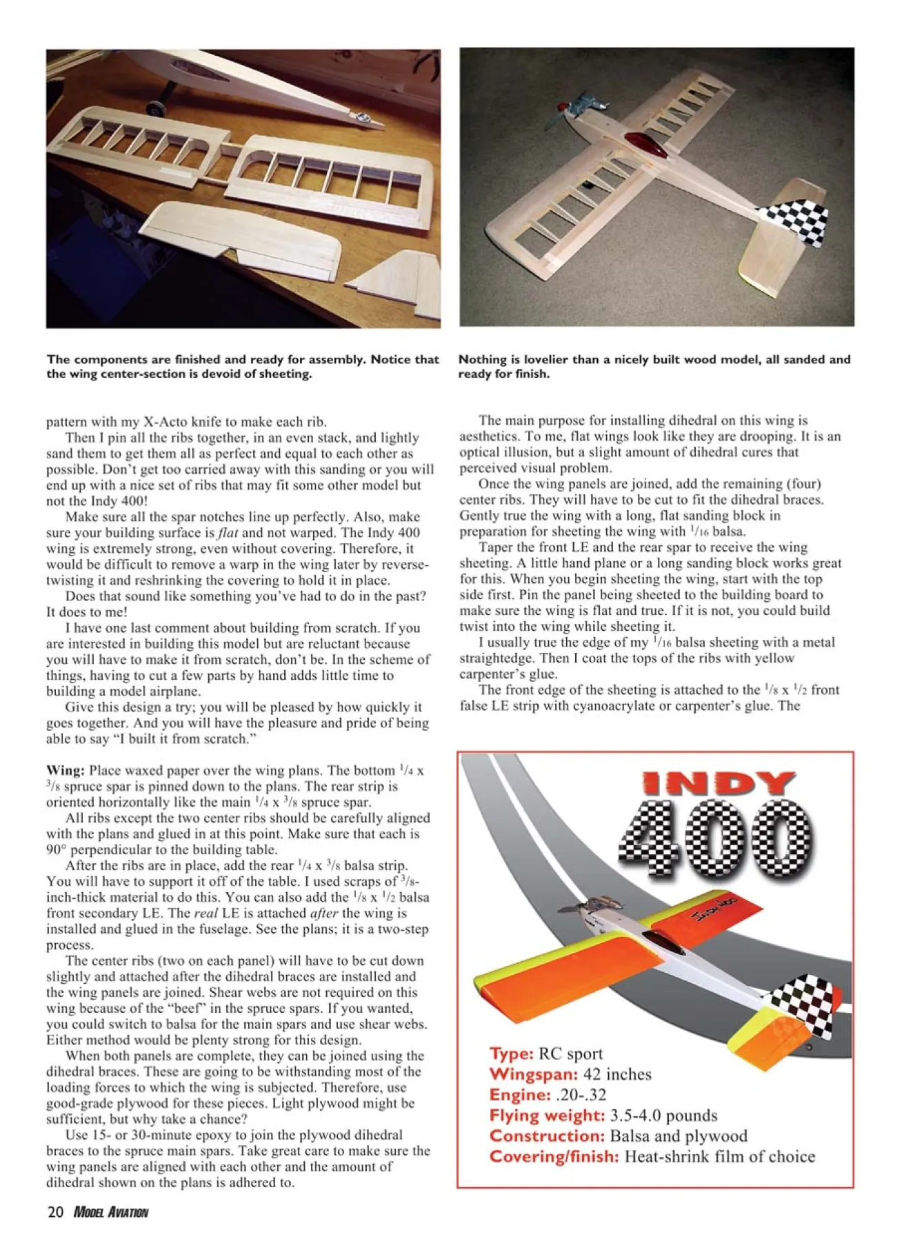
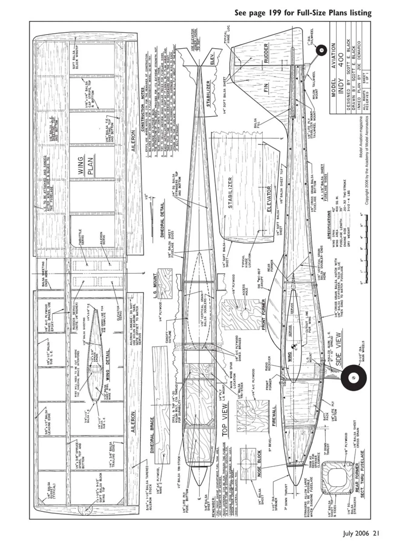

