
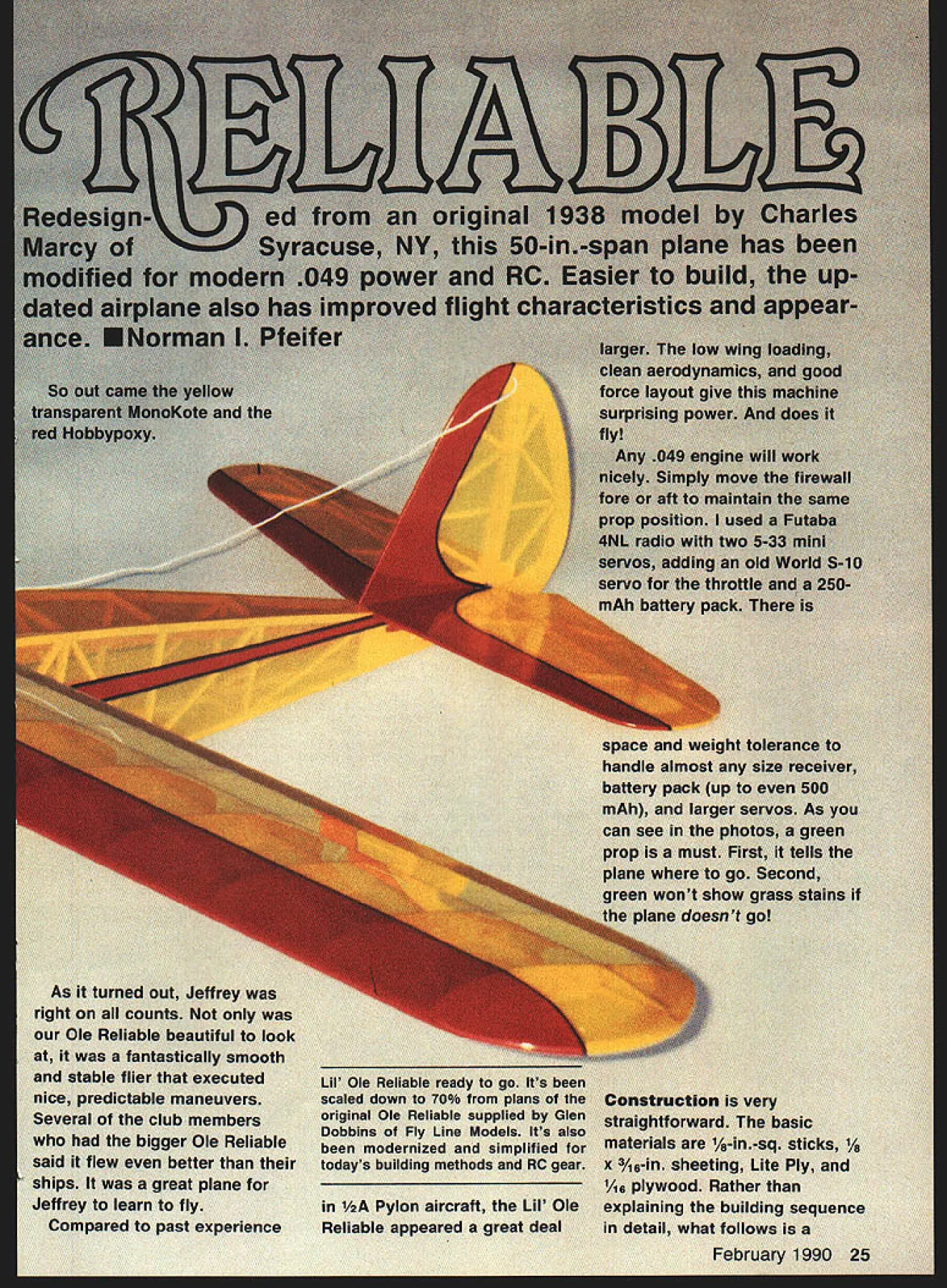
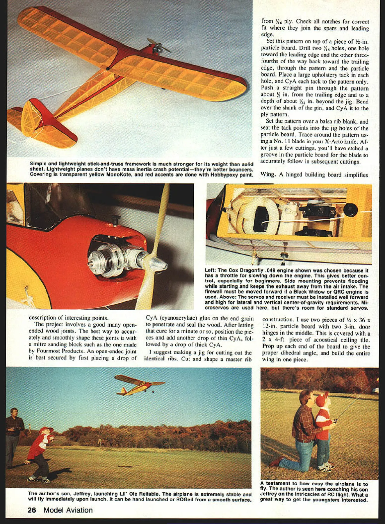
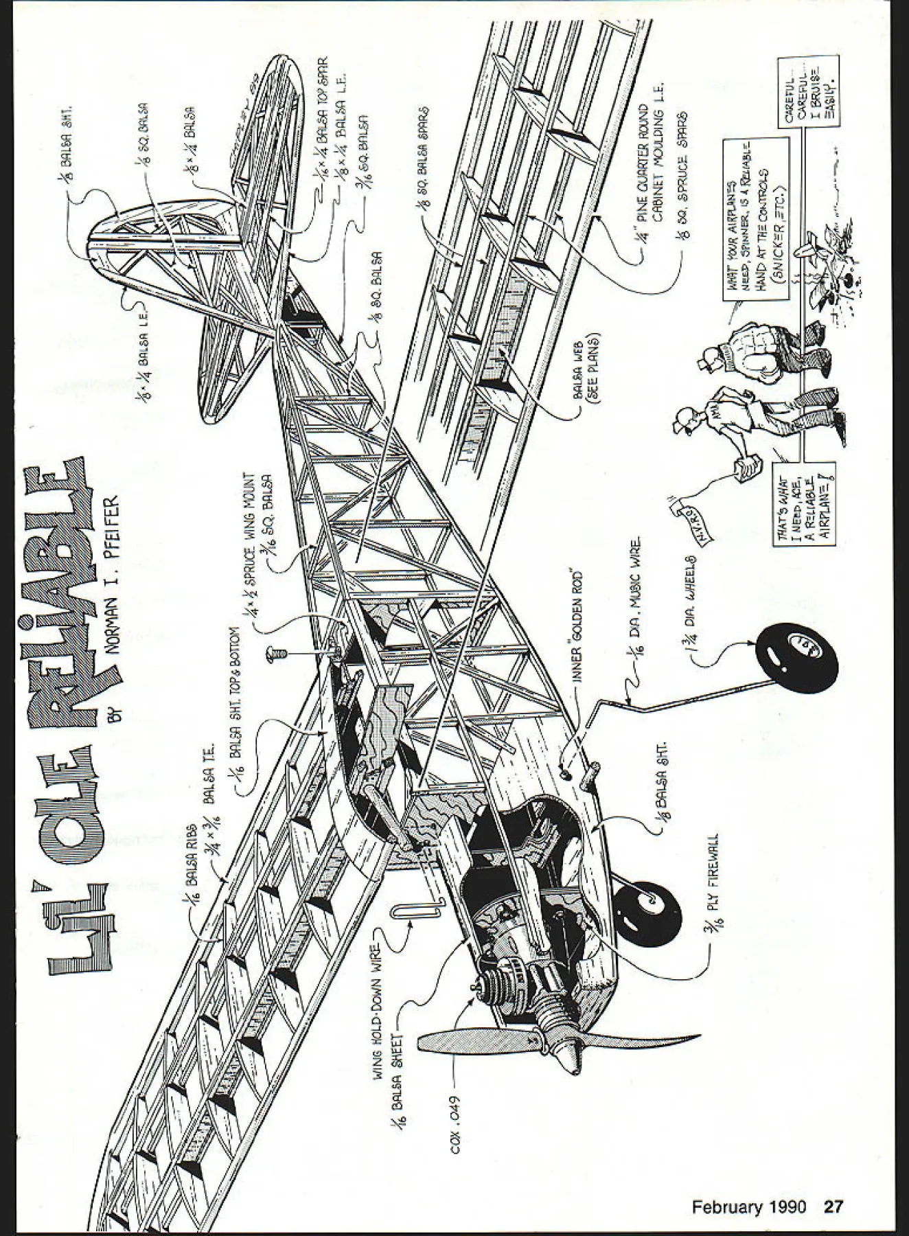
also Ifl Ifle no fun fI Its tip outlin4 e scaling lans Fly L uced thi stabilizer section othis plane given nond airfoil better dung windy con - later full-size del also incorporated As turned out Jeffrey right counts Ole Reliable beautiful look fantastically smooth stable flier executed nice predictable maneuvers Several club members bigger Ole Reliable said flew better ships great plane Jeffrey learn fly Compared past experience Lii Ole Reliable ready go Its scaled down 70% plans original Ole Reliable supplied Glen Dobbins Fly Line Models Its also modernized simplified todays building methods RC gear Pylon aircraft LII Ole Reliable appeared great deal handle tolera size ow gi nt got ConstructIon very straightforward basic materials A-in-sq sticks 1/s x 3A6-in sheeting Lite Ply 1As plywood Rather explaining building sequence detail what follows February 1990 25 Simple lightweight stick-and-truss framework much stronger its weight solid sheet Lightweight planes dont have mass inertia crash potentialtheyre better bouncers Covering transparent yellow MonoKote red accents done Hobbypoxy paint / ply Check notches correct fit join spars leading edge Set pattern top piece -in particle board Drill two /16 holes hole toward leading edge other threefourths way back toward trailing edge through pattern particle board Place large upholstery tack hole CyA tack pattern Push straight pin through pattern about / trailing edge depth about A2 beyond jig Bend over shank pin CyA ply pattern Set pattern over balsa rib blank seat tack points jig holes particle board Trace around pattern us ing No 11 blade X-Acto knife Af ter just few cuttings youll have etched groove particle board blade accurately follow subsequent cuttings Wing hinged building board simplifies description interesting points project involves good openended wood joints best way accur ately smoothly shape joints mitre sanding block such made Fourmost Products An open-ended joint best secured first placing drop CyA cyanoacrylate glue end grain penetrate seal wood After letting cure minute position pie ces add another drop thin CyA fol lowed drop thick CyA suggest making jig cutting out identical ribs Cut shape master rib construction use two pieces /2 x 36 x 12-in particle board two 3-in door hinges middle covered 2 x 4-ft piece acoustical ceiling tile Prop up end board give proper dihedral angle build entire wing piece authors son Jeffrey launching Lii Ole Reliable airplane extremely stable will fly immediately upon launch can hand launched ROGed smooth surface 26 Model Aviation uu uirpiarie I5 TO flyouiIor seen coaching son Jeffrey intricacies RC flight What great way get youngsters interested Left Cox Dragonfly 049 engine shown chosen because has throttle slowing down engine gives better con trol especially beginners Side mounting prevents flooding starting keeps exhaust away air intake firewall must moved forward Black Widow QRC engine used Above servos receiver must installed well forward high lateral vertical center-of-gravity requirements Mi croservos used theres room standard servos m I9FEIFER No - 5RL RIBG 9/4X BRL8P TE C k BRL& LE$ I 8 Q BL5R 4 BLfl WING hOLD-DOWN 4 BRL 8MEET WI J I3flL$fl GHT TOPS BOTTOM x3PRUCE WING MOUNT IC%63QBRL K /1 INNER GOLDEN ROD k2 16 DIR MUIC WIIE DIR WMEEL& WArs hhqA BL L&R 9PRRG 7 1/ ----- I WEB C9EE PLPNC9 4 PINE OUPRTER ROJND CRBINET MOULDING L E NEW FNJER 5 4 fLfALi NAN Ar T79 CoJTROL 6NICKERTC EFUL. ZAEFUL 4GI 151 - GRL IT 1 COX 049 TOPPRR LE - RL 81-iT PLI flREWRLL Cut out wing parts ribs tips dihe dral brace gussets webbing sheets trailing edge notches easily made two hacksaw blades clamped together Adjust pin tips trailing edge cen ter flat rear planking bottom spars over plans position CyA ribs /16 ply dihedral brace place Fit vertical-grained spar webs making sure theyre accurately positioned no gaps CyA place Note diminishing web thickness toward tip Anytime solid structure ends abruptly stress will concentrated point can result fracture progressively dispersing stress problem prevented Trim webbing height CyA top spars place like use -in quarter-round cabinet molding local lumberyard leading edge molding very strong too heavy dent proof leading edge radius already formed slight trimming lower con tour required after CyAed place Remove wing building board Add bottom front sheeting /6 dowel support block center Y16 gussets Drill A-in hole through dowel sup port block just under behind leading edge angling up through webbing just above A-in spruce bottom spar wing hold-down dowel Fit -in dowel dont glue point will epoxied later after trial fitting fuselage sanding wing its much easier sand shape wing dowel sticking out Fit CyA top center planking Block sand wing shape tips Following sanding contour line shown plans tips half-rounded ward front spar match leading edge Behind front spar progressively DIHEDRAL 2-I/A UNDER EACH WIND TIP 1/8 SO BALSA II REAR SPARS U TOP B BOTTOM 2K I/IA BALSA WEB SPAR1EII I/IA 1/4I/BBALSA SHEETVA I/ BALSA T P III 7/S BILl R /1 j7-~ Si I/B I/4 BALSA-T~I I/BBALSA SHEETI/B SO JDINERBALSA I/B LITE PIY S/IA PLY I/IA BALSA SHEET 3/IA BALSA F-I_____ I/IA PLYI/BBALSA SIDES 3/IA 3/B L A PAIRINGI/B LITE PLY WINS HOLD SOWN WIRE-BINS IN PLACE I/B BALSAINNER SOLDEN SHEET SIDESRODB F-2I/IA PLY BOTTOM I/IA DIG MSSIC WIRE LANDING GEAR contour thickness trailing edge Stabilizer fin/rudder Cut out A-in sheet tips rudder trailing edge center pieces Adjust fit pin over plans along /8 x -in lead ing edge trailing edge hinge line spars Add A-in-sq balsa ribs Both fin/rudder stabilizer/eleva tors built flat sure leave A-in fin slot center stabilizer Block sand top bottom stabilizer now since will difficult later challenging part building stabilizer creating diamond-shaped lifting airfoil end A-in-sq rib under cut /16 spar passes over allows spar trimmed tucked inside edge A-in sheet tip forming airfoil tapers flat tip easy cover Add /16 x %-in balsa center section carrying front spar leading edge back edge spar binge line Sand two areas evenly create diamond section 28 Model Aviation simple straight lines model have proved very airworthy Note plug-in landing gear held place shock-absorbing rubberbands part bounce factor / Close-up view simple effective throttle control system Cox Dragonfly en gine solder-stiffened cable end Z-bend makes simple effective connector Full-Size Plans Available. See Page 188 BALSAI/IN PLY HOLDN G PLAN TOP VIEWTIP CONTOUR DOE STOCKDOWN REINFORCEMENTWISANDING LINE 3/16 BALSA/"VI6 BALSAii/6 BALSA GUSSETS"~SHEET-TOP I SHEET RBS -Y_ B BOTTOM I/B BALSA WEI/IN PLYII3/ N BALSA VERT GRAINDIHEDRALIIIISKEET WINS BRACETP /3/IN BALSA 41 ThI I2 DOWEL HOLD BALSA 3D BALSASUPPORTI I-/R BALSA WEBTIP FORMER GBDOWN/3/3D BA GAVERT GRANII EBBETWEEN SPARS7 ----I--STAB NOTE AFTER SPAR ID IN PLACE ADD1/4 PINE OGARTER ROUND I/IN 3/B BALSA FROM SPAR TO HINGE LINECABINET MOULDING LEADINGTIP SECT FRONT SPAR TIP SECT REAR SPAR AND TO LE TO FORM CENTER RIB USE1/4 DIGEDGE MONOKOTE TYPE HINGESDOWELVB BALSA ET I/B BALSA ER RIB SHEET TIPSOlD CLEARI/IN PLYWOOD BUTYRATE MAKE SHEET /MAIN RIB 7MAKE IS / I/B l/4 [v32][b-2-10-1-10]]ITIP RIB BALSAWINDSHIELD I/IN PLYDIHEDRAL BRACE BOTTOM RIB PATTERNS ALL RIBS I/IN BALSA SHEET 3/IN SO BALSA LONSERONS FUSELAGE TOP VIEW IIII II Ii III II I/N BALSA SHEET II 3/IN SO BALSARJSDER NOTE SLUT FIN 1/4 I/U SPRUCECROSS MEMBERS/R I/A BALSADOWN INTO STABILIZER ILLI POSITION IS3AN BALSAWINS MOUNTRUDDER POSTNAS INDICATED BY ARROWS ASONFLY ADJUST GUSSETS ACNWIDOW OR I/B BALSA I/B 1/4 BALSA GUSSETS I/IN BALSAI/B BALSA3/IN SO BALSALEADING EDGEFl \-I/R SO BALSA GUSSETNA 3/INI3/IN SO BALSASTAB MOUNT LSASHEETINGBALSALONDERDOST BALSARIRS AND BRACING WINS HOLD DOWN BOLTI/B BALSA SHEET / -CIN id I 4 [v32][b156414970600]] TYPICAL HINGE LOCATION F--SI / XrZT""T "7 II4I/A BALSA SHEET-NOTE DRAIN TV 41 -II---jI/H BALSA SHEETSTARILIZER /I ALGAF-I p5F-S3/IN SOLR 55 BALSA UPRIGHTS L/R 53BALSAAND DIAGONALS ATTACH LA TOBALSA 1/4 DIG DOWEL3/IN SO BALSA TE ORIGINAL 1938 DESIGN WITH RUBBER BANDSLONSERONS- BOTTOMBY CHARLES MARCY OF SYRACUSEMODEL AVIATION T 3/INNEW YORK LIL OLE RELIABLE ANSOENGINE049 TOE IN WHEELS 3FUSELAGE SIDE VIEWCHORDN-S/BWEIGHT IN-IROS AREA311 DO INSCALE FACT TOYDESIGNED BY NORMAN PFEIPER GLSNA BALSA SHEET SIDES0r234N NTRACING BY JOE DEMARCO ALL RIGHTS RESERVED Block sand stabilizer elevator fin/rudder sanding top stabilizer protect top spar being sanded covering piece mask ing tape spar should have flat top sec tion covering will attached top spar leading edge hinge line Stretched between three points will form desired diamond airfoil section Round off leading tip edges stabilizer fin soft neutral control desired round trailing edges rud der elevators also definite responsive control desired keep trailing edges square sharp Fuselage Cut out A-in sheet balsa nose section A-in Lite Ply balsa formers i/IN ply firewall Position engine firewall aligning thrust line shown plans Mark drill mounting holes install 3-48 blind mounting nuts youre planning use throttle drill throttle cable hole point originally used much lower thrust line shown raised engine February 1990 29 tail surfaces fuselage covered hinged painted before final assembly sure strip Covering material tail-joining surfaces before gluing tail place realized downthrust required Cox 049 would buried nose making access needle valve fuel filler tubing very difficult make things difficult can avoided little pre-planning9 engine mounted firewall set assembly over plans move engine fore aft determine po sition want good prop starter spring clearance Mark position plans drawing new line parallel firewall position shown Cox 049 engines have different lengths position has determined partic ular youre installing Pin A-in sheet nose section over plans position pin Y-sq balsa outline stabilizer mount fuselage uprights Fit CyA double-CyA end grain A-in-sq balsa pieces gus sets control rod exit filler pieces assembled flat building board es will protrude shorter ones thats OK assembly dry remove right side plans Block sand smooth side pieces dont protrude Repin fuselage building board smooth side up pinning side just enough hold place Cover smooth side wax paper fit CyA left side over pieces pro truding match right side assembly dry remove block sand smooth outer left side Place right side over plans mark firewall position previously de termined line drew plans Transfer mark left side Position F-2 F-3 side Using square ensure theyre perfectly verti cal double-CyA pieces place Re member since plywood edges end-grained require initial applica tion thin CyA before final attachment fuselage Position CyA second side top F-2 F-3 Use square ensure accurate alignment tail nose side pieces jig works nicely bending align ing remainder fuselage hand alignment easy too marked cen terlines formers firewall sight down interior fuselage check meet exactly Pull tail gether sight down centerlines add Y6-sq crossmembers time checking centerlines watching twist go along Pull nose together epoxy firewall place Block sand fuselage top bottom Mark /6-in bottom nose reduction undercut / plywood bottom Add engine compartment floor half-bottom nose fairing block Glue bottom /i6 plywood Install servos pushrods point can still reach easily servo mounting used / x /z x 67A6-in Lite Ply side rails CyAed inside A-in sq pieces F-2 F-3 /4 x %-in spruce cross rails Install servos battery receiver high far forward possible fuselage Mounting low will lower vertical center-of-gravity producing pen dulum effect harms airplanes rolling characteristics lowered center-ofgravity also hits center lateral area reduces spiral spin stability Electric guys install batteries bottom Wing mounting should done point Notch F-2 dowel clearance Bend front wire hold-down hori zontal vertical ends per plans scrap end Kwik Link makes good hold-down wire Mark horizontal bend location wire wing place position wire over wing dowel onto F-2 Mark horizontal bend location onto former drill two % holes bend hor izontal portion wire Reposition wire check see holes must altered correct fit Bend vertical end slip wire through holes Double-check fit good capture dowel Drill /16 holes side wire lace soft wire pliers mash vertical ends wire back side F-2 Add 2in spruce trailing edge hold-down block /16 ply reinforcement top wing trailing edge Drill tap wing once its accu rate alignment youre satisfied wing alignment wire hold-down Continued page 32 30 Model Aviation Close-up wing tip structure must carefully contoured sanded blend smoothly half-rounded leading edge neatly faired blend trailing edge Left author son prepping Lil Ole Reliable another flight Jeffrey using Astro Flight mini electric starter no longer manufactured start enginea real finger saver young old alike Right Young Jeffrey learning art RC aircraft maintenance 4 0 i @0 0 SAVE YOUR PLANE SNUFVlBE Isolation Mounting Kits FOR ALL METAL oe GLASS FILLED ENGINE MOUNTS SNUF-VIBE MOUNTING detigned isolate engIne viboatlon end reduce noise Unlike other IsolatIon devIces SNUF-VIBE engine bolts completely encased neoprene rubber mount firewall double IsolatIon dampenIng 0SNUFF-VIBF &lufta Out aIr frame vIbratIon Snuffs Out vIbratIonal noise Extenos fatigue lIfe senaltive R/O equipment controls Installs minutes PreventaengIneahalceatlowRPM Does change firewall apsolng Mows lighter weight constructIon Sn uff-Vibe TWO CYCLE DRILLED AND TAPPED Jt-EV4COV 0NYAAXO5450t Jr-F4068sVI FOX 40 08 JT#40-XV FOX 40 RIO JT-F4OXV F0X45R40oriorsv Jr400Ev IRVINS 30awe 1791008 IRvINE 384- Re JY-Neist IRVINE 51 RIO JT42X5V KS C R/D R/ow 17054550 KS C Re ffNSOsSVI ics 5poW Jr-02e150 K&551 RIO 17-WOWMAX SF08 PP JT4108XVMAX08 PUt JT-M358V1440 3040 PP 17401050MAX 40 PUt JT-MUXVMAX 40SF-4SSF JtM508VMAXOOFUt JTM515VWAd P5951 5F 170110650 MAX 61-106 PUt JT0815V CT TOt-U-fl J74T4050 5T4840-44 47SToiXVI E7sIoo 47arsisv arcouoe,soo JT5T18V CT ~00 1rvsAnsv Y545 JTY5985V VCu41 55 1008 1098 15 1408 1008 1098 1400 I&98 IBJa 15U 1408 1418 1808 1595 mon 1796 Is-as 2795 1498 005 1098 1096 2795 lags 474150 J7-458V 172080 JT-445V 474a50 17550 Jrnv 1712050 JT4350 474054 170050 175550 1710850 ne-N ii\ OlOmENE 1-bin b 98. E SIZES Esch kit contalnes fourJT5325V 6-32 bolts 795 complete SNUFF-VIBE setsJTS32SV 8-32 bolts 895 easy instructIonsJT1O32SV 10-32 bolts 995 Isolated Engine Mounts JA SNUF-V1BE equipped- resdyio install Diiled end tapped fit engines Cast aluminum engine mounts Prenaion machined bright polislisti nnl a08AbJ 94 hobby shot DRDER DIRECT inmdg Eopwnt Chest MD. Vs. MC o CDD 98094 440 633010 UPS 830010 CDO end 0% 5495 Mo 010 sslOsnl. SEND OSO DR STAMP FDRAOOrTIONAI NP M4DJTEC CATALOG 1~ 171545v YsIXO ras1 0045 CI-lIN UNDRILLED MOUNTS Long Basins 47-ISSYAvsq1sZsdbp1188 JT405VAq SF454491098 171850Ame 50454491096 1rissnvAn19058lUdI92108 position apply coat thin CyA pene trate followed thick CyA fillet wire place Finish top nose wing fairing block Add F-2A /I6 balsa planking Add triangle stock pieces modified %-in triangle stock top %-in block Finally sand shape fuselage Landing Gear plug-in landing gear simplifies covering dont like cover around bumps rubberbands good shock-absorbers Jeffrey fly over grass rubberbands plane would flip over landing time Instead flips over 981% time Dont use two small light rubberbands side Bend gear wire shown plans adjusting axle length wheel thick ness Drill two holes fuselage sides /8-in-dia toward top flush back F-2 A-in hole low flush front F-2 Place piece yellow No 10 inner Golden Rod through fuselage CyA place sides back F-2 Choose piece longer what need prevent CyA getting inside Also place piece wire inside Golden Rod CyA keep nice straight Trim Golden Rod flush fuselage sides A-in dowel CyAed place after covering Covering final assembly Final sand subassemblies until quite smooth model covered yellow trans parent MonoKote seams really disappear impressed MonoKote hinge used eleva tors rudder trailing edge hinge line stabilizer left square leading edge elevator beveled back bottom about 45 degrees facilitate movement Place piece masking tape top hinge line temporary hinge hold position elevator folded back covering bottom Cover bot tom first elevator folded back over hinge line onto stabilizer fin rudder covered hinged same way Remove temporary masking tape top hinge cover top section elevator deflected down position creates good hinge also sealing hinge gap covering lower portion tail post about 3A6-in forward overhang left free After tail post glued overhang ironed onto fuselage give nice joint Check wing tail surfaces warps straighten out find wing straight block up trailing edge V8 tip rib hold wing flat up last main rib heat top cov ering produce / washout tips washout tips will Continued page 111 32 Model Aviation POUR CYCLE DRILLED AND TAPPED ENYA35404C1505 ENYA4n-534Clhth ENYAOG-tS-tO-1204CitOh ENYA 6 1204C2705 RIOTOI1818 8PV74et&os hIAXF508lasS tWCF5*40 1505 M8XF5465v1p.1008 MAXF58141 Sop1808 0108 PSOO-7s-90011098 MAX 130108 5op2795 SMIOFA3O1008 50110 PA40451098 ONTOFAXOlogs 54470 PA ES1055 50570 PA 1202795 2795 Ms 164 SCHOOL STREET DALY CITY CA 94014 415 756-3400 see photos runways sur rounded lawns time Solicitation external support Emory other members resulted exceptional contributions other local businesses Bleachers came local parks depart ment Sunscreens bleachers provided another donor Steel columns beams plus roofing made avail able surplus inventory Monsanto open-sided building constructed Curbs paving donated another contractor time read driveways will completely paved scheduled completion time opening clay rain precluded asphalt surface beautiful runway paid Monsanto CRCFM Club good thing about heavy rains grass looked like carpet AMA President Don Lowe attended grand opening Special guests September 17th cluded Don Lowe Lee Webster Dis strict V VP Monsanto represented Bill Perdue plant manager Richard Joslin environmental officer Monsanto office St Louis MO Charles Burroughs state environmental agency present along several city county officials Donors labor services recog nized nice ceremony Emory Cole pre sented certificates plaques trophies commemorate day offer thanks great individuals companies contributed much make model airpark possible Ive visited model flying sites across nation must say best top five certainly top 10 appreciation would like mention names generous businesses helped make Emory Cole Field real ity Damron & Sons Construction Mid Tenn Steel Billy Fitzgerald Plumbing Turner & Osborne Goodwin & Sons Con tractors South & South Maury County Parks Kerr Bros APAC Paving Hunt morials Sloan Ford Columbia Soroptimist Club Columbia Construction Floyd & Floyd Contractors B&F Paving Occiden tal Chemical course Monsanto members Columbia RC Flying Modelers Club ranging age 14 69 years truly grateful wonder ful help contributions have re ceived Led President Emory Cole Vice President Doug Young Secretary Larry Ross Treasurer Roland Descans club has truly great place fly un limited future case sky really limit Note The author director AMA Public Relations Department Lii Ole Reliable/Pfeifer Continued page 32 last part wing stall signifi cantly improves lateral stability red Hobbypoxy applied before sembling stabilizer/elevators-fin/rudderfuselage complex Wipe area painted Hobbypoxy thinner Use cloth paper towel leaves fuzzies Mark outline painted soft pencil Plastic electrical tape works well mask ing off Cut curved lines shape before sticking counteract surface electrostatic properties MonoKote tape has tendency repel paint surface wipe area painted spar ingly white vinegar Spray Hob bypoxy thinly until color evenly dis tributed completely opaque Re move electrical tape soon paint dry touch prevent thick separa tion line Let cure about week before fly ing otherwise abusing paint Sight rear make sure stabilizer horizontal alignment wing Measure tips hinge line ward wing trailing edge making sure hinge line parallel wing everything checks out epoxy CyA stabilizer place Glue fin stabilizer slot tail post rear fuselage Again sight rear ensure tail post correct vertical alignment fin aligned centerline fu selage can look front also wish aid windshield formation hold adapted clear plastic place fingers using heat gun gently heat corner bends fingers wont let get too hot heat will set bend allowing plastic retain its shape Finish installing receiver engine landing gear Check center-ofgravity shown plan add about two ounces lead nose above battery pack Whew Writing labor-intensive building model Lil Ole Reliable neat plane Id again Hmmm maybe Electric version next Flying greatest thrill construc tion project launching new model Nothing can match excitement maiden flight first few magic sec onds unknowns hard work come play flew Lil Ole Reliable first time clubs spring picnic Believe having onlookers really inten sifies first-flight jitters Will wont keeps turning over head least green propand re ally shouldnt have worried much radio worked engine actually started didnt trip hand launched Continued page 142 THE LEADER IN COM PETITION NEW DIA 12 13 14 15 16 NEW PRO SERIES 3 p \ / Ii NEW HIGH TECH AIRFOIL SECTION 10T020% INCREASE IN THRUST MFG OF SELECT HARD MAPLE WOOD WILL NOT FATIGUE LIKE SYNTHETICS FUEL PROOF HIGH LUSTER FINISH DIAPITCH PRICE 534 634 72633h456 8334568 8/45667 94566/77A 104566/,7 106W8W 106EW 114677/7A78 115W 116EW 11/z67 124W 125W 1256 1356 1456 1556 164N 16678 RC PYLON RACING SERIES 500 DIA PITCHPRICE 75N 5/N 6I 6776 SERIES 400C 66677h7 977h7/ W WIDE BLADE EW EXTRA WIDE J MARRAW PROPELLERS CL THP DESIGN TAILORED HELICAL PITCH DEVELOPEDTO GIVE MAXIMUM THRUST AT 4 CYCLE ENGINE RPM ALL THE LATEST TECHNIQUES USED ON OUR PRO SERIES 3 SEE BELOW PITCH THP PRICE 66 /77 8 677A 8 677 8 67 678 February 1990 111 SAFE FLYING IS NO ACCIDENT Fun Len Funds ESCAPE SPECIFICATION. Wing Span62Y2 inches Wing Area770 square inches Engine Size 10 cc 90 120 faur stroke Designed AMA FAI Turn-around pattern Foam wing stab 3-32 Balsa sheet covering Tricycle conven tional gear fixed retracts Rear side exhaust fiber glass canopy Veiy positive man'verable XLT SPECIFIC Wing Span65 inches Length65 inches Wing Area845 square inches Recommended Engine Size 10 cc 90 120 four stroke XLT designed tuned pipe re tract landing gears Capable AMA Turn-around pattern Rear side ex haust SPECIFICATIONS Wing Span63Y4 inches Wing Area700 square inches Engine Size50-60 Glow 90 four stroke Forfun sport pattern turn-around can done Utter Chaos completely built up Balsa construction Canopy engine mount included years proven eying reliablity BRIDI AIRCRAFT DESIGNS INC 23625 Pineforest Lane Harbor City California 90710 213 549-8264 213 326-5013 SEE YOUR FAVORITE HOBBY SHOP OR RETAIL OUTLETW Dealer Inquries Invited AOSORO Sf1000 00 ISF0A1 001 00000 DOFFOODfTIAL 15010 00000 0000 00000 00000 000000 00000000 00t40000000 0SflY 0J05TA0t0 00000000-0000 001000 0S0 ON000LLATIOO OAT 01 100010100 00 00 0110008 0000011 01IOT0 INSTAOUTIOO P0CO000 flhnO 0n0ded LII Ole Reliable/Pfeifer Continued page 111 Lii Ole Reliable hadnt flown six feet 137 seconds knew worth effort Jeffreys sixyear-old instincts right target model flies dad want fly Jeffrey like No buts Prop Noise Continued page 35 craft noise prop noise 2 main com ponent prop noise caused torque loading blades 3 propellers available generally very inefficient inefficiency leads high torque loads relative thrust produced path model aircraft noise reduc tion therefore clear although perhaps easy Making propellers efficient would reduce noise levels compro mising aircraft performance Next months conclusion will present several useful guide lines modelers follow choosing pro pellers own aircraft Addendum Corrections Part 2 table inadvertently omitted some revisions editorial staff error resulting meanings different intended authors ask read ers review following items con junction Model Propeller Noise article January 1990 issue order obtain proper meanings case italics added emphasis Pg 39 first col first para first sen tence Should read opeller noise sources hibit characteristic pattern noise radiates away propeller Pg39 second col second para first sentence Should read echoic re fers condition sound nor re flected use sound-absorbent material simulate free-field acoustic environ ment aircraft flight COMPACT ELECTRIC RC HERE 0edSI0 or50 Wolt tigh 1ff oeoey Motor Sorogsol Propoo4tells Powers 310 24oo Models Si lSSlwPostegeeeHendllng Pg 40 first col first full para omitted Table listing propellers used testing follows Table 1Propellers Included Data Base Manufacturer Size ManufacturerSize Zinger8 x 6Rev-Up11 x 6 EW Zinger9 x6Rev-Up lix 7 Rev-Up9 x 6 Zinger 12 x 6 Master10 x 6Tornado 9 x 6 Three-blade propeller Pg 40 first col first full para second sentence Propellers chosen ing typical use today abil iry 05 Max 046 SF engine turn Pg 40 third col second full para De lete Propeller noise always occurs blade passing frequency does reach crescendo Pg 40 third col last para third fourth sentences An efficient propeller will produce thrust same en gine output same flight conditions An inefficient propeller causes engine work turn prop producing little thrust Pg 41 first col first para ad vance ratio denoted symbol J pro portional ratio Pg 148 second col first para last sen tence ops efficient high speeds will provide reduced noise lev els compared less efficient props same performance levels Pg 148 second col first full para last sentence n reasonably suspect measured noise source fact torque noise regret omission errors Carl R Wheeley Editor Publisher responding advertisers mention read about Model Aviation 142 Model Aviation

Edition: Model Aviation - 1990/02
Page Numbers: 24, 25, 26, 27, 28, 29, 30, 32, 111, 142
Edition: Model Aviation - 1990/02
Page Numbers: 24, 25, 26, 27, 28, 29, 30, 32, 111, 142
also Ifl Ifle no fun fI Its tip outlin4 e scaling lans Fly L uced thi stabilizer section othis plane given nond airfoil better dung windy con - later full-size del also incorporated As turned out Jeffrey right counts Ole Reliable beautiful look fantastically smooth stable flier executed nice predictable maneuvers Several club members bigger Ole Reliable said flew better ships great plane Jeffrey learn fly Compared past experience Lii Ole Reliable ready go Its scaled down 70% plans original Ole Reliable supplied Glen Dobbins Fly Line Models Its also modernized simplified todays building methods RC gear Pylon aircraft LII Ole Reliable appeared great deal handle tolera size ow gi nt got ConstructIon very straightforward basic materials A-in-sq sticks 1/s x 3A6-in sheeting Lite Ply 1As plywood Rather explaining building sequence detail what follows February 1990 25 Simple lightweight stick-and-truss framework much stronger its weight solid sheet Lightweight planes dont have mass inertia crash potentialtheyre better bouncers Covering transparent yellow MonoKote red accents done Hobbypoxy paint / ply Check notches correct fit join spars leading edge Set pattern top piece -in particle board Drill two /16 holes hole toward leading edge other threefourths way back toward trailing edge through pattern particle board Place large upholstery tack hole CyA tack pattern Push straight pin through pattern about / trailing edge depth about A2 beyond jig Bend over shank pin CyA ply pattern Set pattern over balsa rib blank seat tack points jig holes particle board Trace around pattern us ing No 11 blade X-Acto knife Af ter just few cuttings youll have etched groove particle board blade accurately follow subsequent cuttings Wing hinged building board simplifies description interesting points project involves good openended wood joints best way accur ately smoothly shape joints mitre sanding block such made Fourmost Products An open-ended joint best secured first placing drop CyA cyanoacrylate glue end grain penetrate seal wood After letting cure minute position pie ces add another drop thin CyA fol lowed drop thick CyA suggest making jig cutting out identical ribs Cut shape master rib construction use two pieces /2 x 36 x 12-in particle board two 3-in door hinges middle covered 2 x 4-ft piece acoustical ceiling tile Prop up end board give proper dihedral angle build entire wing piece authors son Jeffrey launching Lii Ole Reliable airplane extremely stable will fly immediately upon launch can hand launched ROGed smooth surface 26 Model Aviation uu uirpiarie I5 TO flyouiIor seen coaching son Jeffrey intricacies RC flight What great way get youngsters interested Left Cox Dragonfly 049 engine shown chosen because has throttle slowing down engine gives better con trol especially beginners Side mounting prevents flooding starting keeps exhaust away air intake firewall must moved forward Black Widow QRC engine used Above servos receiver must installed well forward high lateral vertical center-of-gravity requirements Mi croservos used theres room standard servos m I9FEIFER No - 5RL RIBG 9/4X BRL8P TE C k BRL& LE$ I 8 Q BL5R 4 BLfl WING hOLD-DOWN 4 BRL 8MEET WI J I3flL$fl GHT TOPS BOTTOM x3PRUCE WING MOUNT IC%63QBRL K /1 INNER GOLDEN ROD k2 16 DIR MUIC WIIE DIR WMEEL& WArs hhqA BL L&R 9PRRG 7 1/ ----- I WEB C9EE PLPNC9 4 PINE OUPRTER ROJND CRBINET MOULDING L E NEW FNJER 5 4 fLfALi NAN Ar T79 CoJTROL 6NICKERTC EFUL. ZAEFUL 4GI 151 - GRL IT 1 COX 049 TOPPRR LE - RL 81-iT PLI flREWRLL Cut out wing parts ribs tips dihe dral brace gussets webbing sheets trailing edge notches easily made two hacksaw blades clamped together Adjust pin tips trailing edge cen ter flat rear planking bottom spars over plans position CyA ribs /16 ply dihedral brace place Fit vertical-grained spar webs making sure theyre accurately positioned no gaps CyA place Note diminishing web thickness toward tip Anytime solid structure ends abruptly stress will concentrated point can result fracture progressively dispersing stress problem prevented Trim webbing height CyA top spars place like use -in quarter-round cabinet molding local lumberyard leading edge molding very strong too heavy dent proof leading edge radius already formed slight trimming lower con tour required after CyAed place Remove wing building board Add bottom front sheeting /6 dowel support block center Y16 gussets Drill A-in hole through dowel sup port block just under behind leading edge angling up through webbing just above A-in spruce bottom spar wing hold-down dowel Fit -in dowel dont glue point will epoxied later after trial fitting fuselage sanding wing its much easier sand shape wing dowel sticking out Fit CyA top center planking Block sand wing shape tips Following sanding contour line shown plans tips half-rounded ward front spar match leading edge Behind front spar progressively DIHEDRAL 2-I/A UNDER EACH WIND TIP 1/8 SO BALSA II REAR SPARS U TOP B BOTTOM 2K I/IA BALSA WEB SPAR1EII I/IA 1/4I/BBALSA SHEETVA I/ BALSA T P III 7/S BILl R /1 j7-~ Si I/B I/4 BALSA-T~I I/BBALSA SHEETI/B SO JDINERBALSA I/B LITE PIY S/IA PLY I/IA BALSA SHEET 3/IA BALSA F-I_____ I/IA PLYI/BBALSA SIDES 3/IA 3/B L A PAIRINGI/B LITE PLY WINS HOLD SOWN WIRE-BINS IN PLACE I/B BALSAINNER SOLDEN SHEET SIDESRODB F-2I/IA PLY BOTTOM I/IA DIG MSSIC WIRE LANDING GEAR contour thickness trailing edge Stabilizer fin/rudder Cut out A-in sheet tips rudder trailing edge center pieces Adjust fit pin over plans along /8 x -in lead ing edge trailing edge hinge line spars Add A-in-sq balsa ribs Both fin/rudder stabilizer/eleva tors built flat sure leave A-in fin slot center stabilizer Block sand top bottom stabilizer now since will difficult later challenging part building stabilizer creating diamond-shaped lifting airfoil end A-in-sq rib under cut /16 spar passes over allows spar trimmed tucked inside edge A-in sheet tip forming airfoil tapers flat tip easy cover Add /16 x %-in balsa center section carrying front spar leading edge back edge spar binge line Sand two areas evenly create diamond section 28 Model Aviation simple straight lines model have proved very airworthy Note plug-in landing gear held place shock-absorbing rubberbands part bounce factor / Close-up view simple effective throttle control system Cox Dragonfly en gine solder-stiffened cable end Z-bend makes simple effective connector Full-Size Plans Available. See Page 188 BALSAI/IN PLY HOLDN G PLAN TOP VIEWTIP CONTOUR DOE STOCKDOWN REINFORCEMENTWISANDING LINE 3/16 BALSA/"VI6 BALSAii/6 BALSA GUSSETS"~SHEET-TOP I SHEET RBS -Y_ B BOTTOM I/B BALSA WEI/IN PLYII3/ N BALSA VERT GRAINDIHEDRALIIIISKEET WINS BRACETP /3/IN BALSA 41 ThI I2 DOWEL HOLD BALSA 3D BALSASUPPORTI I-/R BALSA WEBTIP FORMER GBDOWN/3/3D BA GAVERT GRANII EBBETWEEN SPARS7 ----I--STAB NOTE AFTER SPAR ID IN PLACE ADD1/4 PINE OGARTER ROUND I/IN 3/B BALSA FROM SPAR TO HINGE LINECABINET MOULDING LEADINGTIP SECT FRONT SPAR TIP SECT REAR SPAR AND TO LE TO FORM CENTER RIB USE1/4 DIGEDGE MONOKOTE TYPE HINGESDOWELVB BALSA ET I/B BALSA ER RIB SHEET TIPSOlD CLEARI/IN PLYWOOD BUTYRATE MAKE SHEET /MAIN RIB 7MAKE IS / I/B l/4 [v32][b-2-10-1-10]]ITIP RIB BALSAWINDSHIELD I/IN PLYDIHEDRAL BRACE BOTTOM RIB PATTERNS ALL RIBS I/IN BALSA SHEET 3/IN SO BALSA LONSERONS FUSELAGE TOP VIEW IIII II Ii III II I/N BALSA SHEET II 3/IN SO BALSARJSDER NOTE SLUT FIN 1/4 I/U SPRUCECROSS MEMBERS/R I/A BALSADOWN INTO STABILIZER ILLI POSITION IS3AN BALSAWINS MOUNTRUDDER POSTNAS INDICATED BY ARROWS ASONFLY ADJUST GUSSETS ACNWIDOW OR I/B BALSA I/B 1/4 BALSA GUSSETS I/IN BALSAI/B BALSA3/IN SO BALSALEADING EDGEFl \-I/R SO BALSA GUSSETNA 3/INI3/IN SO BALSASTAB MOUNT LSASHEETINGBALSALONDERDOST BALSARIRS AND BRACING WINS HOLD DOWN BOLTI/B BALSA SHEET / -CIN id I 4 [v32][b156414970600]] TYPICAL HINGE LOCATION F--SI / XrZT""T "7 II4I/A BALSA SHEET-NOTE DRAIN TV 41 -II---jI/H BALSA SHEETSTARILIZER /I ALGAF-I p5F-S3/IN SOLR 55 BALSA UPRIGHTS L/R 53BALSAAND DIAGONALS ATTACH LA TOBALSA 1/4 DIG DOWEL3/IN SO BALSA TE ORIGINAL 1938 DESIGN WITH RUBBER BANDSLONSERONS- BOTTOMBY CHARLES MARCY OF SYRACUSEMODEL AVIATION T 3/INNEW YORK LIL OLE RELIABLE ANSOENGINE049 TOE IN WHEELS 3FUSELAGE SIDE VIEWCHORDN-S/BWEIGHT IN-IROS AREA311 DO INSCALE FACT TOYDESIGNED BY NORMAN PFEIPER GLSNA BALSA SHEET SIDES0r234N NTRACING BY JOE DEMARCO ALL RIGHTS RESERVED Block sand stabilizer elevator fin/rudder sanding top stabilizer protect top spar being sanded covering piece mask ing tape spar should have flat top sec tion covering will attached top spar leading edge hinge line Stretched between three points will form desired diamond airfoil section Round off leading tip edges stabilizer fin soft neutral control desired round trailing edges rud der elevators also definite responsive control desired keep trailing edges square sharp Fuselage Cut out A-in sheet balsa nose section A-in Lite Ply balsa formers i/IN ply firewall Position engine firewall aligning thrust line shown plans Mark drill mounting holes install 3-48 blind mounting nuts youre planning use throttle drill throttle cable hole point originally used much lower thrust line shown raised engine February 1990 29 tail surfaces fuselage covered hinged painted before final assembly sure strip Covering material tail-joining surfaces before gluing tail place realized downthrust required Cox 049 would buried nose making access needle valve fuel filler tubing very difficult make things difficult can avoided little pre-planning9 engine mounted firewall set assembly over plans move engine fore aft determine po sition want good prop starter spring clearance Mark position plans drawing new line parallel firewall position shown Cox 049 engines have different lengths position has determined partic ular youre installing Pin A-in sheet nose section over plans position pin Y-sq balsa outline stabilizer mount fuselage uprights Fit CyA double-CyA end grain A-in-sq balsa pieces gus sets control rod exit filler pieces assembled flat building board es will protrude shorter ones thats OK assembly dry remove right side plans Block sand smooth side pieces dont protrude Repin fuselage building board smooth side up pinning side just enough hold place Cover smooth side wax paper fit CyA left side over pieces pro truding match right side assembly dry remove block sand smooth outer left side Place right side over plans mark firewall position previously de termined line drew plans Transfer mark left side Position F-2 F-3 side Using square ensure theyre perfectly verti cal double-CyA pieces place Re member since plywood edges end-grained require initial applica tion thin CyA before final attachment fuselage Position CyA second side top F-2 F-3 Use square ensure accurate alignment tail nose side pieces jig works nicely bending align ing remainder fuselage hand alignment easy too marked cen terlines formers firewall sight down interior fuselage check meet exactly Pull tail gether sight down centerlines add Y6-sq crossmembers time checking centerlines watching twist go along Pull nose together epoxy firewall place Block sand fuselage top bottom Mark /6-in bottom nose reduction undercut / plywood bottom Add engine compartment floor half-bottom nose fairing block Glue bottom /i6 plywood Install servos pushrods point can still reach easily servo mounting used / x /z x 67A6-in Lite Ply side rails CyAed inside A-in sq pieces F-2 F-3 /4 x %-in spruce cross rails Install servos battery receiver high far forward possible fuselage Mounting low will lower vertical center-of-gravity producing pen dulum effect harms airplanes rolling characteristics lowered center-ofgravity also hits center lateral area reduces spiral spin stability Electric guys install batteries bottom Wing mounting should done point Notch F-2 dowel clearance Bend front wire hold-down hori zontal vertical ends per plans scrap end Kwik Link makes good hold-down wire Mark horizontal bend location wire wing place position wire over wing dowel onto F-2 Mark horizontal bend location onto former drill two % holes bend hor izontal portion wire Reposition wire check see holes must altered correct fit Bend vertical end slip wire through holes Double-check fit good capture dowel Drill /16 holes side wire lace soft wire pliers mash vertical ends wire back side F-2 Add 2in spruce trailing edge hold-down block /16 ply reinforcement top wing trailing edge Drill tap wing once its accu rate alignment youre satisfied wing alignment wire hold-down Continued page 32 30 Model Aviation Close-up wing tip structure must carefully contoured sanded blend smoothly half-rounded leading edge neatly faired blend trailing edge Left author son prepping Lil Ole Reliable another flight Jeffrey using Astro Flight mini electric starter no longer manufactured start enginea real finger saver young old alike Right Young Jeffrey learning art RC aircraft maintenance 4 0 i @0 0 SAVE YOUR PLANE SNUFVlBE Isolation Mounting Kits FOR ALL METAL oe GLASS FILLED ENGINE MOUNTS SNUF-VIBE MOUNTING detigned isolate engIne viboatlon end reduce noise Unlike other IsolatIon devIces SNUF-VIBE engine bolts completely encased neoprene rubber mount firewall double IsolatIon dampenIng 0SNUFF-VIBF &lufta Out aIr frame vIbratIon Snuffs Out vIbratIonal noise Extenos fatigue lIfe senaltive R/O equipment controls Installs minutes PreventaengIneahalceatlowRPM Does change firewall apsolng Mows lighter weight constructIon Sn uff-Vibe TWO CYCLE DRILLED AND TAPPED Jt-EV4COV 0NYAAXO5450t Jr-F4068sVI FOX 40 08 JT#40-XV FOX 40 RIO JT-F4OXV F0X45R40oriorsv Jr400Ev IRVINS 30awe 1791008 IRvINE 384- Re JY-Neist IRVINE 51 RIO JT42X5V KS C R/D R/ow 17054550 KS C Re ffNSOsSVI ics 5poW Jr-02e150 K&551 RIO 17-WOWMAX SF08 PP JT4108XVMAX08 PUt JT-M358V1440 3040 PP 17401050MAX 40 PUt JT-MUXVMAX 40SF-4SSF JtM508VMAXOOFUt JTM515VWAd P5951 5F 170110650 MAX 61-106 PUt JT0815V CT TOt-U-fl J74T4050 5T4840-44 47SToiXVI E7sIoo 47arsisv arcouoe,soo JT5T18V CT ~00 1rvsAnsv Y545 JTY5985V VCu41 55 1008 1098 15 1408 1008 1098 1400 I&98 IBJa 15U 1408 1418 1808 1595 mon 1796 Is-as 2795 1498 005 1098 1096 2795 lags 474150 J7-458V 172080 JT-445V 474a50 17550 Jrnv 1712050 JT4350 474054 170050 175550 1710850 ne-N ii\ OlOmENE 1-bin b 98. E SIZES Esch kit contalnes fourJT5325V 6-32 bolts 795 complete SNUFF-VIBE setsJTS32SV 8-32 bolts 895 easy instructIonsJT1O32SV 10-32 bolts 995 Isolated Engine Mounts JA SNUF-V1BE equipped- resdyio install Diiled end tapped fit engines Cast aluminum engine mounts Prenaion machined bright polislisti nnl a08AbJ 94 hobby shot DRDER DIRECT inmdg Eopwnt Chest MD. Vs. MC o CDD 98094 440 633010 UPS 830010 CDO end 0% 5495 Mo 010 sslOsnl. SEND OSO DR STAMP FDRAOOrTIONAI NP M4DJTEC CATALOG 1~ 171545v YsIXO ras1 0045 CI-lIN UNDRILLED MOUNTS Long Basins 47-ISSYAvsq1sZsdbp1188 JT405VAq SF454491098 171850Ame 50454491096 1rissnvAn19058lUdI92108 position apply coat thin CyA pene trate followed thick CyA fillet wire place Finish top nose wing fairing block Add F-2A /I6 balsa planking Add triangle stock pieces modified %-in triangle stock top %-in block Finally sand shape fuselage Landing Gear plug-in landing gear simplifies covering dont like cover around bumps rubberbands good shock-absorbers Jeffrey fly over grass rubberbands plane would flip over landing time Instead flips over 981% time Dont use two small light rubberbands side Bend gear wire shown plans adjusting axle length wheel thick ness Drill two holes fuselage sides /8-in-dia toward top flush back F-2 A-in hole low flush front F-2 Place piece yellow No 10 inner Golden Rod through fuselage CyA place sides back F-2 Choose piece longer what need prevent CyA getting inside Also place piece wire inside Golden Rod CyA keep nice straight Trim Golden Rod flush fuselage sides A-in dowel CyAed place after covering Covering final assembly Final sand subassemblies until quite smooth model covered yellow trans parent MonoKote seams really disappear impressed MonoKote hinge used eleva tors rudder trailing edge hinge line stabilizer left square leading edge elevator beveled back bottom about 45 degrees facilitate movement Place piece masking tape top hinge line temporary hinge hold position elevator folded back covering bottom Cover bot tom first elevator folded back over hinge line onto stabilizer fin rudder covered hinged same way Remove temporary masking tape top hinge cover top section elevator deflected down position creates good hinge also sealing hinge gap covering lower portion tail post about 3A6-in forward overhang left free After tail post glued overhang ironed onto fuselage give nice joint Check wing tail surfaces warps straighten out find wing straight block up trailing edge V8 tip rib hold wing flat up last main rib heat top cov ering produce / washout tips washout tips will Continued page 111 32 Model Aviation POUR CYCLE DRILLED AND TAPPED ENYA35404C1505 ENYA4n-534Clhth ENYAOG-tS-tO-1204CitOh ENYA 6 1204C2705 RIOTOI1818 8PV74et&os hIAXF508lasS tWCF5*40 1505 M8XF5465v1p.1008 MAXF58141 Sop1808 0108 PSOO-7s-90011098 MAX 130108 5op2795 SMIOFA3O1008 50110 PA40451098 ONTOFAXOlogs 54470 PA ES1055 50570 PA 1202795 2795 Ms 164 SCHOOL STREET DALY CITY CA 94014 415 756-3400 see photos runways sur rounded lawns time Solicitation external support Emory other members resulted exceptional contributions other local businesses Bleachers came local parks depart ment Sunscreens bleachers provided another donor Steel columns beams plus roofing made avail able surplus inventory Monsanto open-sided building constructed Curbs paving donated another contractor time read driveways will completely paved scheduled completion time opening clay rain precluded asphalt surface beautiful runway paid Monsanto CRCFM Club good thing about heavy rains grass looked like carpet AMA President Don Lowe attended grand opening Special guests September 17th cluded Don Lowe Lee Webster Dis strict V VP Monsanto represented Bill Perdue plant manager Richard Joslin environmental officer Monsanto office St Louis MO Charles Burroughs state environmental agency present along several city county officials Donors labor services recog nized nice ceremony Emory Cole pre sented certificates plaques trophies commemorate day offer thanks great individuals companies contributed much make model airpark possible Ive visited model flying sites across nation must say best top five certainly top 10 appreciation would like mention names generous businesses helped make Emory Cole Field real ity Damron & Sons Construction Mid Tenn Steel Billy Fitzgerald Plumbing Turner & Osborne Goodwin & Sons Con tractors South & South Maury County Parks Kerr Bros APAC Paving Hunt morials Sloan Ford Columbia Soroptimist Club Columbia Construction Floyd & Floyd Contractors B&F Paving Occiden tal Chemical course Monsanto members Columbia RC Flying Modelers Club ranging age 14 69 years truly grateful wonder ful help contributions have re ceived Led President Emory Cole Vice President Doug Young Secretary Larry Ross Treasurer Roland Descans club has truly great place fly un limited future case sky really limit Note The author director AMA Public Relations Department Lii Ole Reliable/Pfeifer Continued page 32 last part wing stall signifi cantly improves lateral stability red Hobbypoxy applied before sembling stabilizer/elevators-fin/rudderfuselage complex Wipe area painted Hobbypoxy thinner Use cloth paper towel leaves fuzzies Mark outline painted soft pencil Plastic electrical tape works well mask ing off Cut curved lines shape before sticking counteract surface electrostatic properties MonoKote tape has tendency repel paint surface wipe area painted spar ingly white vinegar Spray Hob bypoxy thinly until color evenly dis tributed completely opaque Re move electrical tape soon paint dry touch prevent thick separa tion line Let cure about week before fly ing otherwise abusing paint Sight rear make sure stabilizer horizontal alignment wing Measure tips hinge line ward wing trailing edge making sure hinge line parallel wing everything checks out epoxy CyA stabilizer place Glue fin stabilizer slot tail post rear fuselage Again sight rear ensure tail post correct vertical alignment fin aligned centerline fu selage can look front also wish aid windshield formation hold adapted clear plastic place fingers using heat gun gently heat corner bends fingers wont let get too hot heat will set bend allowing plastic retain its shape Finish installing receiver engine landing gear Check center-ofgravity shown plan add about two ounces lead nose above battery pack Whew Writing labor-intensive building model Lil Ole Reliable neat plane Id again Hmmm maybe Electric version next Flying greatest thrill construc tion project launching new model Nothing can match excitement maiden flight first few magic sec onds unknowns hard work come play flew Lil Ole Reliable first time clubs spring picnic Believe having onlookers really inten sifies first-flight jitters Will wont keeps turning over head least green propand re ally shouldnt have worried much radio worked engine actually started didnt trip hand launched Continued page 142 THE LEADER IN COM PETITION NEW DIA 12 13 14 15 16 NEW PRO SERIES 3 p \ / Ii NEW HIGH TECH AIRFOIL SECTION 10T020% INCREASE IN THRUST MFG OF SELECT HARD MAPLE WOOD WILL NOT FATIGUE LIKE SYNTHETICS FUEL PROOF HIGH LUSTER FINISH DIAPITCH PRICE 534 634 72633h456 8334568 8/45667 94566/77A 104566/,7 106W8W 106EW 114677/7A78 115W 116EW 11/z67 124W 125W 1256 1356 1456 1556 164N 16678 RC PYLON RACING SERIES 500 DIA PITCHPRICE 75N 5/N 6I 6776 SERIES 400C 66677h7 977h7/ W WIDE BLADE EW EXTRA WIDE J MARRAW PROPELLERS CL THP DESIGN TAILORED HELICAL PITCH DEVELOPEDTO GIVE MAXIMUM THRUST AT 4 CYCLE ENGINE RPM ALL THE LATEST TECHNIQUES USED ON OUR PRO SERIES 3 SEE BELOW PITCH THP PRICE 66 /77 8 677A 8 677 8 67 678 February 1990 111 SAFE FLYING IS NO ACCIDENT Fun Len Funds ESCAPE SPECIFICATION. Wing Span62Y2 inches Wing Area770 square inches Engine Size 10 cc 90 120 faur stroke Designed AMA FAI Turn-around pattern Foam wing stab 3-32 Balsa sheet covering Tricycle conven tional gear fixed retracts Rear side exhaust fiber glass canopy Veiy positive man'verable XLT SPECIFIC Wing Span65 inches Length65 inches Wing Area845 square inches Recommended Engine Size 10 cc 90 120 four stroke XLT designed tuned pipe re tract landing gears Capable AMA Turn-around pattern Rear side ex haust SPECIFICATIONS Wing Span63Y4 inches Wing Area700 square inches Engine Size50-60 Glow 90 four stroke Forfun sport pattern turn-around can done Utter Chaos completely built up Balsa construction Canopy engine mount included years proven eying reliablity BRIDI AIRCRAFT DESIGNS INC 23625 Pineforest Lane Harbor City California 90710 213 549-8264 213 326-5013 SEE YOUR FAVORITE HOBBY SHOP OR RETAIL OUTLETW Dealer Inquries Invited AOSORO Sf1000 00 ISF0A1 001 00000 DOFFOODfTIAL 15010 00000 0000 00000 00000 000000 00000000 00t40000000 0SflY 0J05TA0t0 00000000-0000 001000 0S0 ON000LLATIOO OAT 01 100010100 00 00 0110008 0000011 01IOT0 INSTAOUTIOO P0CO000 flhnO 0n0ded LII Ole Reliable/Pfeifer Continued page 111 Lii Ole Reliable hadnt flown six feet 137 seconds knew worth effort Jeffreys sixyear-old instincts right target model flies dad want fly Jeffrey like No buts Prop Noise Continued page 35 craft noise prop noise 2 main com ponent prop noise caused torque loading blades 3 propellers available generally very inefficient inefficiency leads high torque loads relative thrust produced path model aircraft noise reduc tion therefore clear although perhaps easy Making propellers efficient would reduce noise levels compro mising aircraft performance Next months conclusion will present several useful guide lines modelers follow choosing pro pellers own aircraft Addendum Corrections Part 2 table inadvertently omitted some revisions editorial staff error resulting meanings different intended authors ask read ers review following items con junction Model Propeller Noise article January 1990 issue order obtain proper meanings case italics added emphasis Pg 39 first col first para first sen tence Should read opeller noise sources hibit characteristic pattern noise radiates away propeller Pg39 second col second para first sentence Should read echoic re fers condition sound nor re flected use sound-absorbent material simulate free-field acoustic environ ment aircraft flight COMPACT ELECTRIC RC HERE 0edSI0 or50 Wolt tigh 1ff oeoey Motor Sorogsol Propoo4tells Powers 310 24oo Models Si lSSlwPostegeeeHendllng Pg 40 first col first full para omitted Table listing propellers used testing follows Table 1Propellers Included Data Base Manufacturer Size ManufacturerSize Zinger8 x 6Rev-Up11 x 6 EW Zinger9 x6Rev-Up lix 7 Rev-Up9 x 6 Zinger 12 x 6 Master10 x 6Tornado 9 x 6 Three-blade propeller Pg 40 first col first full para second sentence Propellers chosen ing typical use today abil iry 05 Max 046 SF engine turn Pg 40 third col second full para De lete Propeller noise always occurs blade passing frequency does reach crescendo Pg 40 third col last para third fourth sentences An efficient propeller will produce thrust same en gine output same flight conditions An inefficient propeller causes engine work turn prop producing little thrust Pg 41 first col first para ad vance ratio denoted symbol J pro portional ratio Pg 148 second col first para last sen tence ops efficient high speeds will provide reduced noise lev els compared less efficient props same performance levels Pg 148 second col first full para last sentence n reasonably suspect measured noise source fact torque noise regret omission errors Carl R Wheeley Editor Publisher responding advertisers mention read about Model Aviation 142 Model Aviation
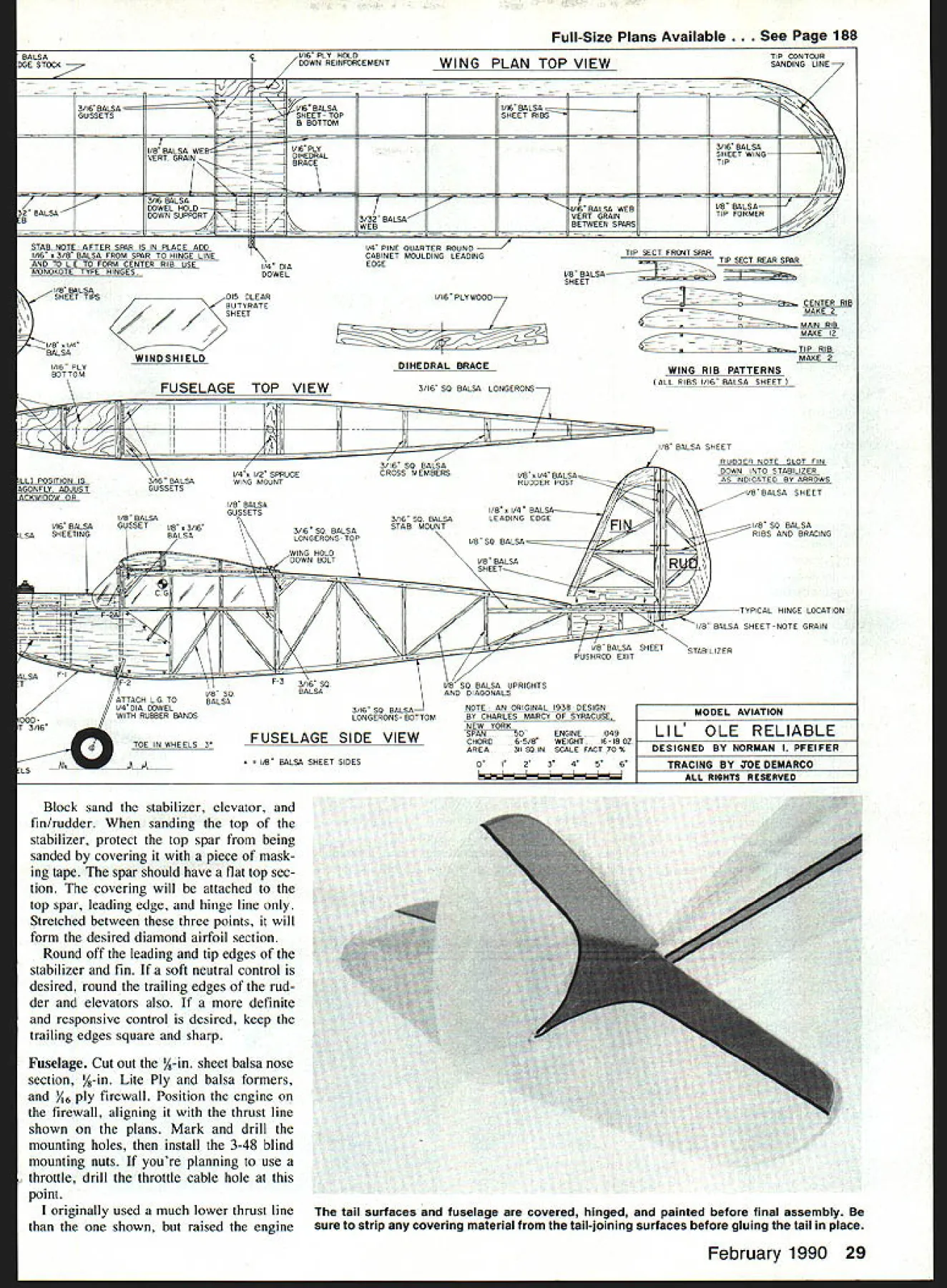

