
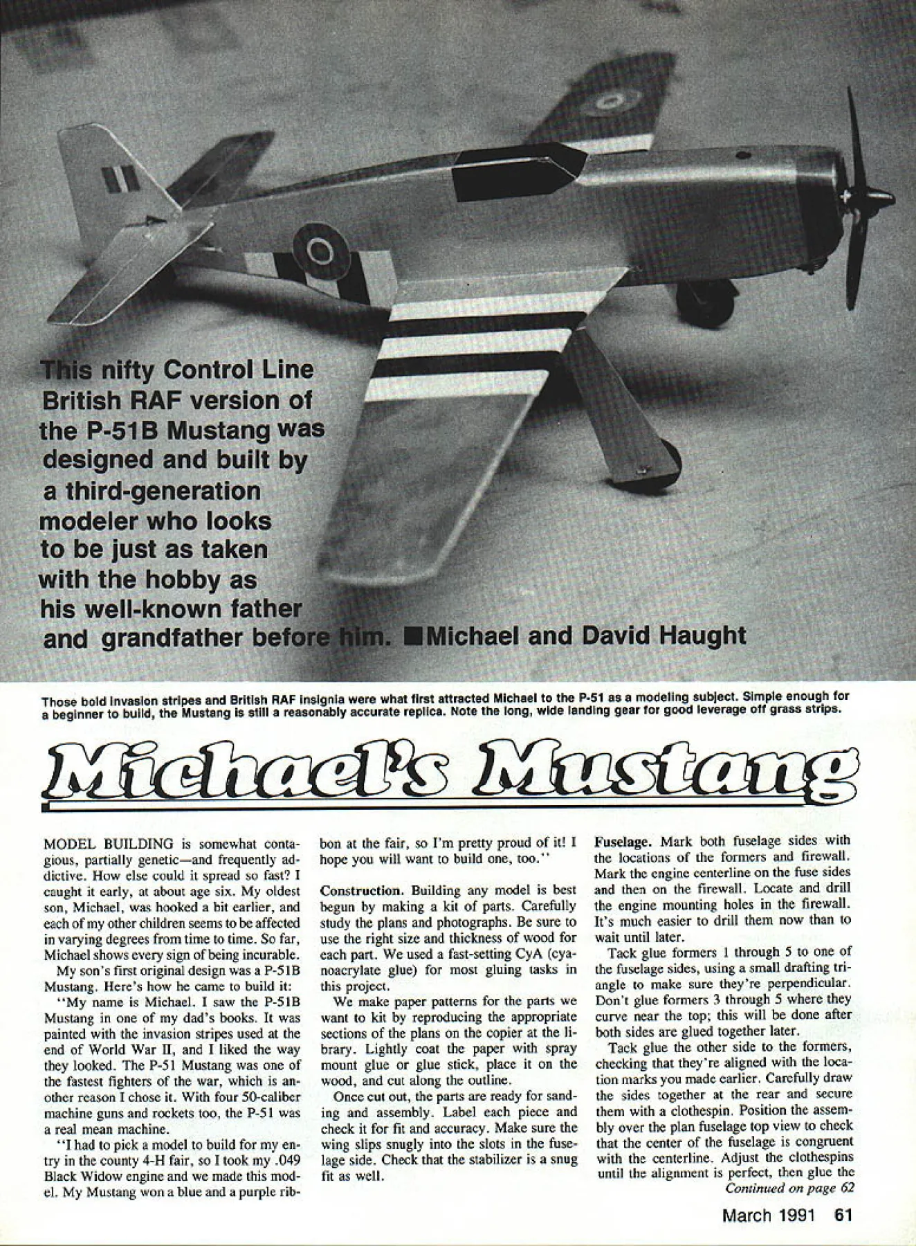
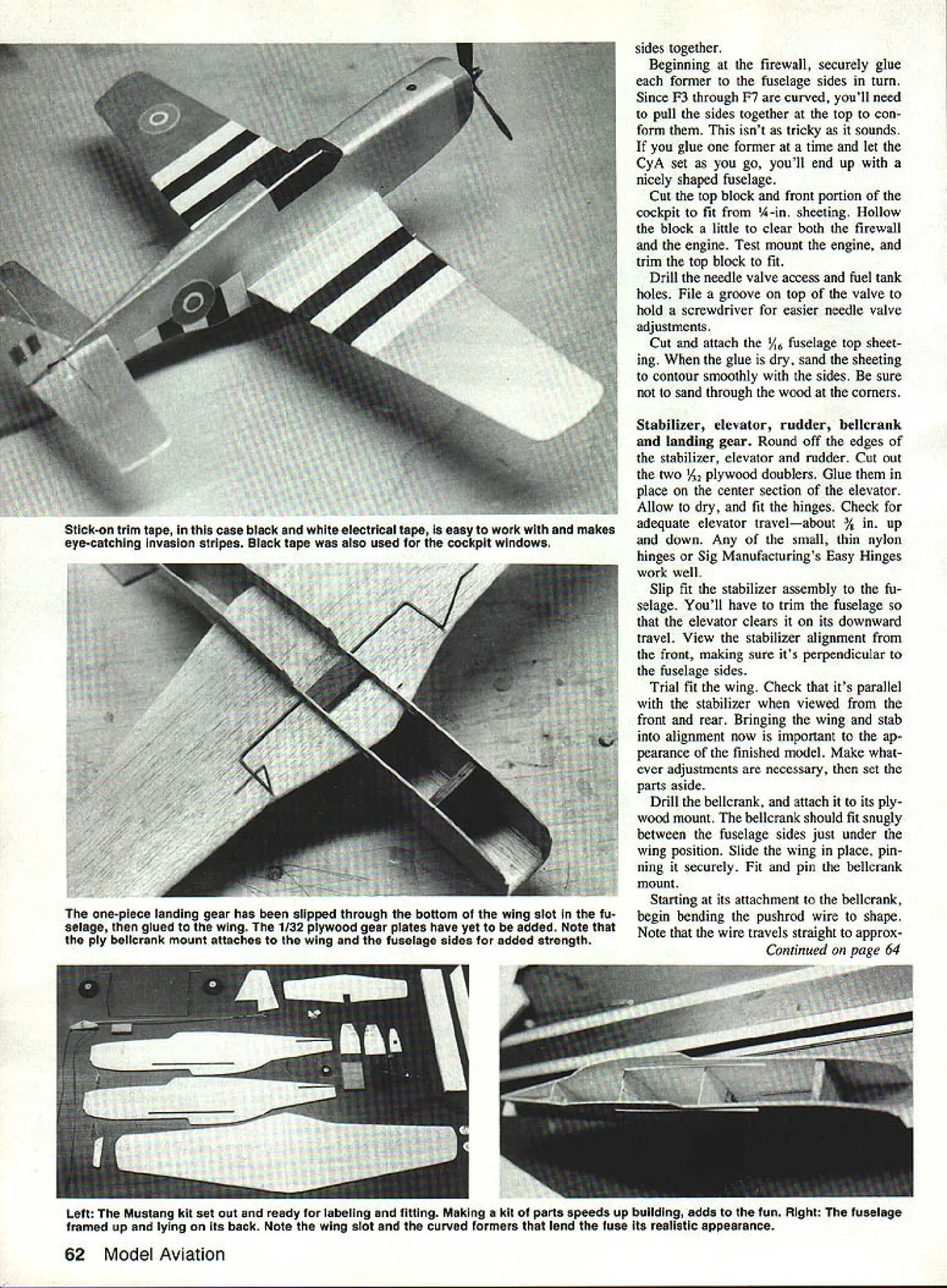
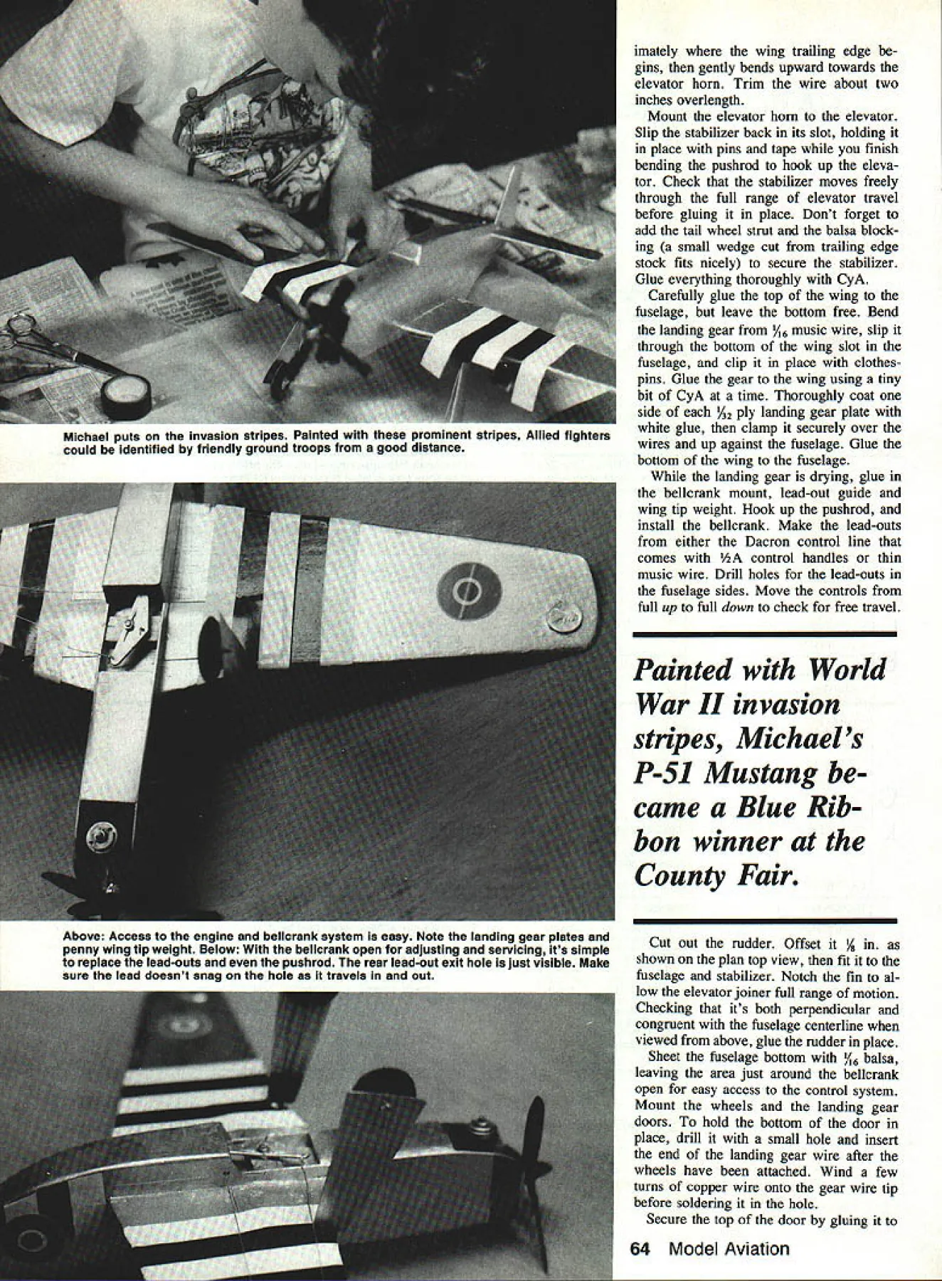
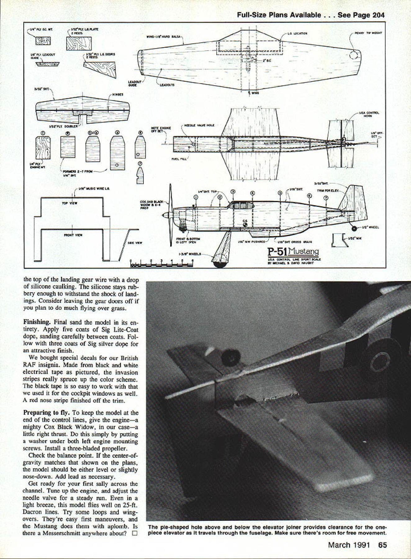
Those bold invasion stripes British RAF Insignia what first attracted Michael P-51 modeiing subject Simple enough beginner build Mustang stili reasonably accurate replica Note long wide landing gear good leverage off grass strips IIli MODEL BUILDING somewhat conta gious partially geneticand frequently ad dictive else could spread fast caught early about age six oldest son Michael hooked bit earlier other children seems affected varying degrees time time So far Michael shows sign being incurable sons first original design P-SiB Mustang Heres came build name Michael saw P-51B Mustang dads books painted invasion stripes used end World War II liked way looked P-5 1 Mustang fastest fighters war other reason chose four 50-caliber machine guns rockets too P-5 1 real mean machine pick model build en try county 4-H fair took 049 Black Widow engine made mod el Mustang won blue purple ribbon fair Im pretty proud hope will want build too Construction Building model best begun making kit parts Carefully study plans photographs sure use right size thickness wood part used fast-setting CyA cya noacrylate glue gluing tasks project make paper patterns parts want kit reproducing appropriate sections plans copier li brary Lightly coat paper spray mount glue glue stick place wood cut along outline Once cut out parts ready sand ing assembly Label piece check fit accuracy Make sure wing slips snugly slots fuse lage side Check stabilizer snug fit well Fuselage Mark both fuselage sides locations formers firewall Mark engine centerline fuse sides firewall Locate drill engine mounting holes firewall Its much easier drill now wait until later Tack glue formers 1 through 5 fuselage sides using small drafting tri angle make sure theyre perpendicular Dont glue formers 3 through 5 curve near top will done after both sides glued together later Tack glue other side formers checking theyre aligned loca tion marks made earlier Carefully draw sides together rear secure clothespin Position assem bly over plan fuselage top view check center fuselage congruent centerline Adjust clothespins until alignment perfect glue Continued page 62 March 1991 61 sides together Beginning firewall securely glue former fuselage sides turn Since F3 through F7 curved youll need pull sides together top con form isnt tricky sounds glue former time let CyA set go youll end up nicely shaped fuselage Cut top block front portion cockpit fit A-in sheeting Hollow block little clear both firewall engine Test mount engine trim top block fit Drill needle valve access fuel tank holes File groove top valve hold screwdriver easier needle valve adjustments Cut attach A6 fuselage top sheet ing glue dry sand sheeting contour smoothly sides sure sand through wood corners Stabilizer elevator rudder belicrank landing gear Round off edges stabilizer elevator rudder Cut out two / plywood doublers Glue place center section elevator Allow dry fit hinges Check adequate elevator travelabout % up down Any small thin nylon hinges Sig Manufacturings Easy Hinges work well Slip fit stabilizer assembly fu selage Youll have trim fuselage elevator clears its downward travel View stabilizer alignment front making sure its perpendicular fuselage sides Trial fit wing Check its parallel stabilizer viewed front rear Bringing wing stab alignment now important ap pearance finished model Make what ever adjustments necessary set parts aside Drill bellcrank attach its ply wood mount bellcrank should fit snugly between fuselage sides just under wing position Slide wing place pin ning securely Fit pin bellcrank mount Starting its attachment belicrank begin bending pushrod wire shape Note wire travels straight approx Continued page 64 Left The Mustang kit set out ready labeling fitting Making kit parts speeds up building adds fun Right fuselage framed up lying its back Note wing slot curved formers lend fuse its realistic appearance 62 Model Aviation Stick-on trim tape case black white electrical tape easy work makes eye-catching invasion stripes Black tape also used cockpit windows one-piece landing gear has slipped through bottom wing slot fu selage glued wing 1/32 plywood gear plates have yet added Note ply belicrank mount attaches wing fuselage sides added strength imately wing trailing edge gins gently bends upward towards elevator horn Trim wire about two inches overlength Mount elevator horn elevator Slip stabilizer back its slot holding place pins tape finish bending pushrod hook up eleva tor Check stabilizer moves freely through full range elevator travel before gluing place Dont forget add tail wheel strut balsa block ing small wedge cut trailing edge stock fits nicely secure stabilizer Glue everything thoroughly CyA Carefully glue top wing fuselage leave bottom free Bend landing gear /16 music wire slip through bottom wing slot fuselage clip place clothes pins Glue gear wing using tiny bit CyA time Thoroughly coat side /32 ply landing gear plate white glue clamp securely over wires up against fuselage Glue bottom wing fuselage landing gear drying glue bellcrank mount lead-out guide wing tip weight Hook up pushrod install bellcrank Make lead-outs either Dacron control line comes /2A control handles thin music wire Drill holes lead-outs fuselage sides Move controls full up full down check free travel Painted World War II invasion stripes Michaels P-Si Mustang came Blue Rib bon winner County Fair Cut out rudder Offset / shown plan top view fit fuselage stabilizer Notch fin al low elevator joiner full range motion Checking its both perpendicular congruent fuselage centerline viewed above glue rudder place Sheet fuselage bottom /16 balsa leaving area just around bellcrank open easy access control system Mount wheels landing gear doors hold bottom door place drill small hole insert end landing gear wire after wheels have attached Wind few turns copper wire onto gear wire tip before soldering hole Secure top door gluing 64 Model Aviation Michael puts Invasion stripes Painted prominent stripes Allied fighters could identified friendly ground troops good distance Above Access engine belicrank system easy Note ianding gear plates penny wing tip weight Below belicrank open adjusting servicing its simple repiace lead-outs pushrod rear lead-out exit hole just visible Make sure lead doesnt snag hole travels out Full-Size Plans Available. See Page 204 v3rPLy ________ IA PlyU 2-7 PROM ERIEPIE MT V16 SIT 02A COIEIROL HORN E ETr SET FUEL FILLS IdlE MUSIC WIRE LA r lOP VIEW FRORT VIEW SOE VIEW top landing gear wire drop silicone caulking silicone stays rub bery enough withstand shock land ings Consider leaving gear doors off plan much flying over grass Finishing Final sand model its en tirety Apply five coats Sig Lite-Coat dope sanding carefully between coats Fol low three coats Sig silver dope attractive finish bought special decals British RAF insignia Made black white electrical tape pictured invasion stripes really spruce up color scheme black tape easy work used cockpit windows well red nose stripe finished off trim Preparing fly keep model end control lines give enginea mighty Cox Black Widow casea little right thrust simply putting washer under both left engine mounting screws Install three-bladed propeller Check balance point center-ofgravity matches shown plans model should either level slightly nose-down Add lead necessary Get ready first sally across channel Tune up engine adjust needle valve steady run light breeze model flies well 25-ft Dacron lines Try some loops wing overs Theyre easy first maneuvers Mustang does aplomb Messerschmitt anywhere about E COU049 BLAOIvt WIDOW E4if PROP /41 -I FRONT S 5011051 JO LEFT EN I/ESHT TOP 3/32SIT IIlRSIITTRIM FOR ELEV -f# 2 AlIEE Li 232 MW VIE MW PUONROS/IE ONT COOSS NEAR P-51 Nustang EYIaCEAE S SAUD NAUGHT N/DA CONTROL LRE SPORTSCME March 1991 65 IX SC MT I/S PLY LEAOOJT SUSIE 3f FIT LAFLASE ~ES pie-shaped hole above below elevator loiner provides clearance onepiece elevator aa travels through fuselage Make sure theres room free movement
Edition: Model Aviation - 1991/03
Page Numbers: 61, 62, 64, 65
Edition: Model Aviation - 1991/03
Page Numbers: 61, 62, 64, 65
Those bold invasion stripes British RAF Insignia what first attracted Michael P-51 modeiing subject Simple enough beginner build Mustang stili reasonably accurate replica Note long wide landing gear good leverage off grass strips IIli MODEL BUILDING somewhat conta gious partially geneticand frequently ad dictive else could spread fast caught early about age six oldest son Michael hooked bit earlier other children seems affected varying degrees time time So far Michael shows sign being incurable sons first original design P-SiB Mustang Heres came build name Michael saw P-51B Mustang dads books painted invasion stripes used end World War II liked way looked P-5 1 Mustang fastest fighters war other reason chose four 50-caliber machine guns rockets too P-5 1 real mean machine pick model build en try county 4-H fair took 049 Black Widow engine made mod el Mustang won blue purple ribbon fair Im pretty proud hope will want build too Construction Building model best begun making kit parts Carefully study plans photographs sure use right size thickness wood part used fast-setting CyA cya noacrylate glue gluing tasks project make paper patterns parts want kit reproducing appropriate sections plans copier li brary Lightly coat paper spray mount glue glue stick place wood cut along outline Once cut out parts ready sand ing assembly Label piece check fit accuracy Make sure wing slips snugly slots fuse lage side Check stabilizer snug fit well Fuselage Mark both fuselage sides locations formers firewall Mark engine centerline fuse sides firewall Locate drill engine mounting holes firewall Its much easier drill now wait until later Tack glue formers 1 through 5 fuselage sides using small drafting tri angle make sure theyre perpendicular Dont glue formers 3 through 5 curve near top will done after both sides glued together later Tack glue other side formers checking theyre aligned loca tion marks made earlier Carefully draw sides together rear secure clothespin Position assem bly over plan fuselage top view check center fuselage congruent centerline Adjust clothespins until alignment perfect glue Continued page 62 March 1991 61 sides together Beginning firewall securely glue former fuselage sides turn Since F3 through F7 curved youll need pull sides together top con form isnt tricky sounds glue former time let CyA set go youll end up nicely shaped fuselage Cut top block front portion cockpit fit A-in sheeting Hollow block little clear both firewall engine Test mount engine trim top block fit Drill needle valve access fuel tank holes File groove top valve hold screwdriver easier needle valve adjustments Cut attach A6 fuselage top sheet ing glue dry sand sheeting contour smoothly sides sure sand through wood corners Stabilizer elevator rudder belicrank landing gear Round off edges stabilizer elevator rudder Cut out two / plywood doublers Glue place center section elevator Allow dry fit hinges Check adequate elevator travelabout % up down Any small thin nylon hinges Sig Manufacturings Easy Hinges work well Slip fit stabilizer assembly fu selage Youll have trim fuselage elevator clears its downward travel View stabilizer alignment front making sure its perpendicular fuselage sides Trial fit wing Check its parallel stabilizer viewed front rear Bringing wing stab alignment now important ap pearance finished model Make what ever adjustments necessary set parts aside Drill bellcrank attach its ply wood mount bellcrank should fit snugly between fuselage sides just under wing position Slide wing place pin ning securely Fit pin bellcrank mount Starting its attachment belicrank begin bending pushrod wire shape Note wire travels straight approx Continued page 64 Left The Mustang kit set out ready labeling fitting Making kit parts speeds up building adds fun Right fuselage framed up lying its back Note wing slot curved formers lend fuse its realistic appearance 62 Model Aviation Stick-on trim tape case black white electrical tape easy work makes eye-catching invasion stripes Black tape also used cockpit windows one-piece landing gear has slipped through bottom wing slot fu selage glued wing 1/32 plywood gear plates have yet added Note ply belicrank mount attaches wing fuselage sides added strength imately wing trailing edge gins gently bends upward towards elevator horn Trim wire about two inches overlength Mount elevator horn elevator Slip stabilizer back its slot holding place pins tape finish bending pushrod hook up eleva tor Check stabilizer moves freely through full range elevator travel before gluing place Dont forget add tail wheel strut balsa block ing small wedge cut trailing edge stock fits nicely secure stabilizer Glue everything thoroughly CyA Carefully glue top wing fuselage leave bottom free Bend landing gear /16 music wire slip through bottom wing slot fuselage clip place clothes pins Glue gear wing using tiny bit CyA time Thoroughly coat side /32 ply landing gear plate white glue clamp securely over wires up against fuselage Glue bottom wing fuselage landing gear drying glue bellcrank mount lead-out guide wing tip weight Hook up pushrod install bellcrank Make lead-outs either Dacron control line comes /2A control handles thin music wire Drill holes lead-outs fuselage sides Move controls full up full down check free travel Painted World War II invasion stripes Michaels P-Si Mustang came Blue Rib bon winner County Fair Cut out rudder Offset / shown plan top view fit fuselage stabilizer Notch fin al low elevator joiner full range motion Checking its both perpendicular congruent fuselage centerline viewed above glue rudder place Sheet fuselage bottom /16 balsa leaving area just around bellcrank open easy access control system Mount wheels landing gear doors hold bottom door place drill small hole insert end landing gear wire after wheels have attached Wind few turns copper wire onto gear wire tip before soldering hole Secure top door gluing 64 Model Aviation Michael puts Invasion stripes Painted prominent stripes Allied fighters could identified friendly ground troops good distance Above Access engine belicrank system easy Note ianding gear plates penny wing tip weight Below belicrank open adjusting servicing its simple repiace lead-outs pushrod rear lead-out exit hole just visible Make sure lead doesnt snag hole travels out Full-Size Plans Available. See Page 204 v3rPLy ________ IA PlyU 2-7 PROM ERIEPIE MT V16 SIT 02A COIEIROL HORN E ETr SET FUEL FILLS IdlE MUSIC WIRE LA r lOP VIEW FRORT VIEW SOE VIEW top landing gear wire drop silicone caulking silicone stays rub bery enough withstand shock land ings Consider leaving gear doors off plan much flying over grass Finishing Final sand model its en tirety Apply five coats Sig Lite-Coat dope sanding carefully between coats Fol low three coats Sig silver dope attractive finish bought special decals British RAF insignia Made black white electrical tape pictured invasion stripes really spruce up color scheme black tape easy work used cockpit windows well red nose stripe finished off trim Preparing fly keep model end control lines give enginea mighty Cox Black Widow casea little right thrust simply putting washer under both left engine mounting screws Install three-bladed propeller Check balance point center-ofgravity matches shown plans model should either level slightly nose-down Add lead necessary Get ready first sally across channel Tune up engine adjust needle valve steady run light breeze model flies well 25-ft Dacron lines Try some loops wing overs Theyre easy first maneuvers Mustang does aplomb Messerschmitt anywhere about E COU049 BLAOIvt WIDOW E4if PROP /41 -I FRONT S 5011051 JO LEFT EN I/ESHT TOP 3/32SIT IIlRSIITTRIM FOR ELEV -f# 2 AlIEE Li 232 MW VIE MW PUONROS/IE ONT COOSS NEAR P-51 Nustang EYIaCEAE S SAUD NAUGHT N/DA CONTROL LRE SPORTSCME March 1991 65 IX SC MT I/S PLY LEAOOJT SUSIE 3f FIT LAFLASE ~ES pie-shaped hole above below elevator loiner provides clearance onepiece elevator aa travels through fuselage Make sure theres room free movement
Edition: Model Aviation - 1991/03
Page Numbers: 61, 62, 64, 65
Those bold invasion stripes British RAF Insignia what first attracted Michael P-51 modeiing subject Simple enough beginner build Mustang stili reasonably accurate replica Note long wide landing gear good leverage off grass strips IIli MODEL BUILDING somewhat conta gious partially geneticand frequently ad dictive else could spread fast caught early about age six oldest son Michael hooked bit earlier other children seems affected varying degrees time time So far Michael shows sign being incurable sons first original design P-SiB Mustang Heres came build name Michael saw P-51B Mustang dads books painted invasion stripes used end World War II liked way looked P-5 1 Mustang fastest fighters war other reason chose four 50-caliber machine guns rockets too P-5 1 real mean machine pick model build en try county 4-H fair took 049 Black Widow engine made mod el Mustang won blue purple ribbon fair Im pretty proud hope will want build too Construction Building model best begun making kit parts Carefully study plans photographs sure use right size thickness wood part used fast-setting CyA cya noacrylate glue gluing tasks project make paper patterns parts want kit reproducing appropriate sections plans copier li brary Lightly coat paper spray mount glue glue stick place wood cut along outline Once cut out parts ready sand ing assembly Label piece check fit accuracy Make sure wing slips snugly slots fuse lage side Check stabilizer snug fit well Fuselage Mark both fuselage sides locations formers firewall Mark engine centerline fuse sides firewall Locate drill engine mounting holes firewall Its much easier drill now wait until later Tack glue formers 1 through 5 fuselage sides using small drafting tri angle make sure theyre perpendicular Dont glue formers 3 through 5 curve near top will done after both sides glued together later Tack glue other side formers checking theyre aligned loca tion marks made earlier Carefully draw sides together rear secure clothespin Position assem bly over plan fuselage top view check center fuselage congruent centerline Adjust clothespins until alignment perfect glue Continued page 62 March 1991 61 sides together Beginning firewall securely glue former fuselage sides turn Since F3 through F7 curved youll need pull sides together top con form isnt tricky sounds glue former time let CyA set go youll end up nicely shaped fuselage Cut top block front portion cockpit fit A-in sheeting Hollow block little clear both firewall engine Test mount engine trim top block fit Drill needle valve access fuel tank holes File groove top valve hold screwdriver easier needle valve adjustments Cut attach A6 fuselage top sheet ing glue dry sand sheeting contour smoothly sides sure sand through wood corners Stabilizer elevator rudder belicrank landing gear Round off edges stabilizer elevator rudder Cut out two / plywood doublers Glue place center section elevator Allow dry fit hinges Check adequate elevator travelabout % up down Any small thin nylon hinges Sig Manufacturings Easy Hinges work well Slip fit stabilizer assembly fu selage Youll have trim fuselage elevator clears its downward travel View stabilizer alignment front making sure its perpendicular fuselage sides Trial fit wing Check its parallel stabilizer viewed front rear Bringing wing stab alignment now important ap pearance finished model Make what ever adjustments necessary set parts aside Drill bellcrank attach its ply wood mount bellcrank should fit snugly between fuselage sides just under wing position Slide wing place pin ning securely Fit pin bellcrank mount Starting its attachment belicrank begin bending pushrod wire shape Note wire travels straight approx Continued page 64 Left The Mustang kit set out ready labeling fitting Making kit parts speeds up building adds fun Right fuselage framed up lying its back Note wing slot curved formers lend fuse its realistic appearance 62 Model Aviation Stick-on trim tape case black white electrical tape easy work makes eye-catching invasion stripes Black tape also used cockpit windows one-piece landing gear has slipped through bottom wing slot fu selage glued wing 1/32 plywood gear plates have yet added Note ply belicrank mount attaches wing fuselage sides added strength imately wing trailing edge gins gently bends upward towards elevator horn Trim wire about two inches overlength Mount elevator horn elevator Slip stabilizer back its slot holding place pins tape finish bending pushrod hook up eleva tor Check stabilizer moves freely through full range elevator travel before gluing place Dont forget add tail wheel strut balsa block ing small wedge cut trailing edge stock fits nicely secure stabilizer Glue everything thoroughly CyA Carefully glue top wing fuselage leave bottom free Bend landing gear /16 music wire slip through bottom wing slot fuselage clip place clothes pins Glue gear wing using tiny bit CyA time Thoroughly coat side /32 ply landing gear plate white glue clamp securely over wires up against fuselage Glue bottom wing fuselage landing gear drying glue bellcrank mount lead-out guide wing tip weight Hook up pushrod install bellcrank Make lead-outs either Dacron control line comes /2A control handles thin music wire Drill holes lead-outs fuselage sides Move controls full up full down check free travel Painted World War II invasion stripes Michaels P-Si Mustang came Blue Rib bon winner County Fair Cut out rudder Offset / shown plan top view fit fuselage stabilizer Notch fin al low elevator joiner full range motion Checking its both perpendicular congruent fuselage centerline viewed above glue rudder place Sheet fuselage bottom /16 balsa leaving area just around bellcrank open easy access control system Mount wheels landing gear doors hold bottom door place drill small hole insert end landing gear wire after wheels have attached Wind few turns copper wire onto gear wire tip before soldering hole Secure top door gluing 64 Model Aviation Michael puts Invasion stripes Painted prominent stripes Allied fighters could identified friendly ground troops good distance Above Access engine belicrank system easy Note ianding gear plates penny wing tip weight Below belicrank open adjusting servicing its simple repiace lead-outs pushrod rear lead-out exit hole just visible Make sure lead doesnt snag hole travels out Full-Size Plans Available. See Page 204 v3rPLy ________ IA PlyU 2-7 PROM ERIEPIE MT V16 SIT 02A COIEIROL HORN E ETr SET FUEL FILLS IdlE MUSIC WIRE LA r lOP VIEW FRORT VIEW SOE VIEW top landing gear wire drop silicone caulking silicone stays rub bery enough withstand shock land ings Consider leaving gear doors off plan much flying over grass Finishing Final sand model its en tirety Apply five coats Sig Lite-Coat dope sanding carefully between coats Fol low three coats Sig silver dope attractive finish bought special decals British RAF insignia Made black white electrical tape pictured invasion stripes really spruce up color scheme black tape easy work used cockpit windows well red nose stripe finished off trim Preparing fly keep model end control lines give enginea mighty Cox Black Widow casea little right thrust simply putting washer under both left engine mounting screws Install three-bladed propeller Check balance point center-ofgravity matches shown plans model should either level slightly nose-down Add lead necessary Get ready first sally across channel Tune up engine adjust needle valve steady run light breeze model flies well 25-ft Dacron lines Try some loops wing overs Theyre easy first maneuvers Mustang does aplomb Messerschmitt anywhere about E COU049 BLAOIvt WIDOW E4if PROP /41 -I FRONT S 5011051 JO LEFT EN I/ESHT TOP 3/32SIT IIlRSIITTRIM FOR ELEV -f# 2 AlIEE Li 232 MW VIE MW PUONROS/IE ONT COOSS NEAR P-51 Nustang EYIaCEAE S SAUD NAUGHT N/DA CONTROL LRE SPORTSCME March 1991 65 IX SC MT I/S PLY LEAOOJT SUSIE 3f FIT LAFLASE ~ES pie-shaped hole above below elevator loiner provides clearance onepiece elevator aa travels through fuselage Make sure theres room free movement

