
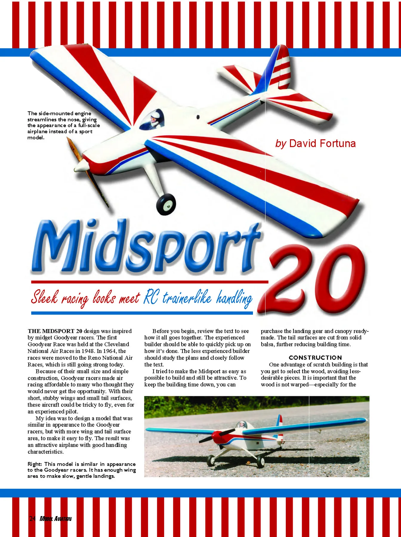
THE MIDSPORT 20 design was inspired
by midget Goodyear racers. The first
Goodyear Race was held at the Cleveland
National Air Races in 1948. In 1964, the
races were moved to the Reno National Air
Races, which is still going strong today.
July 2009 25
Photos by the author
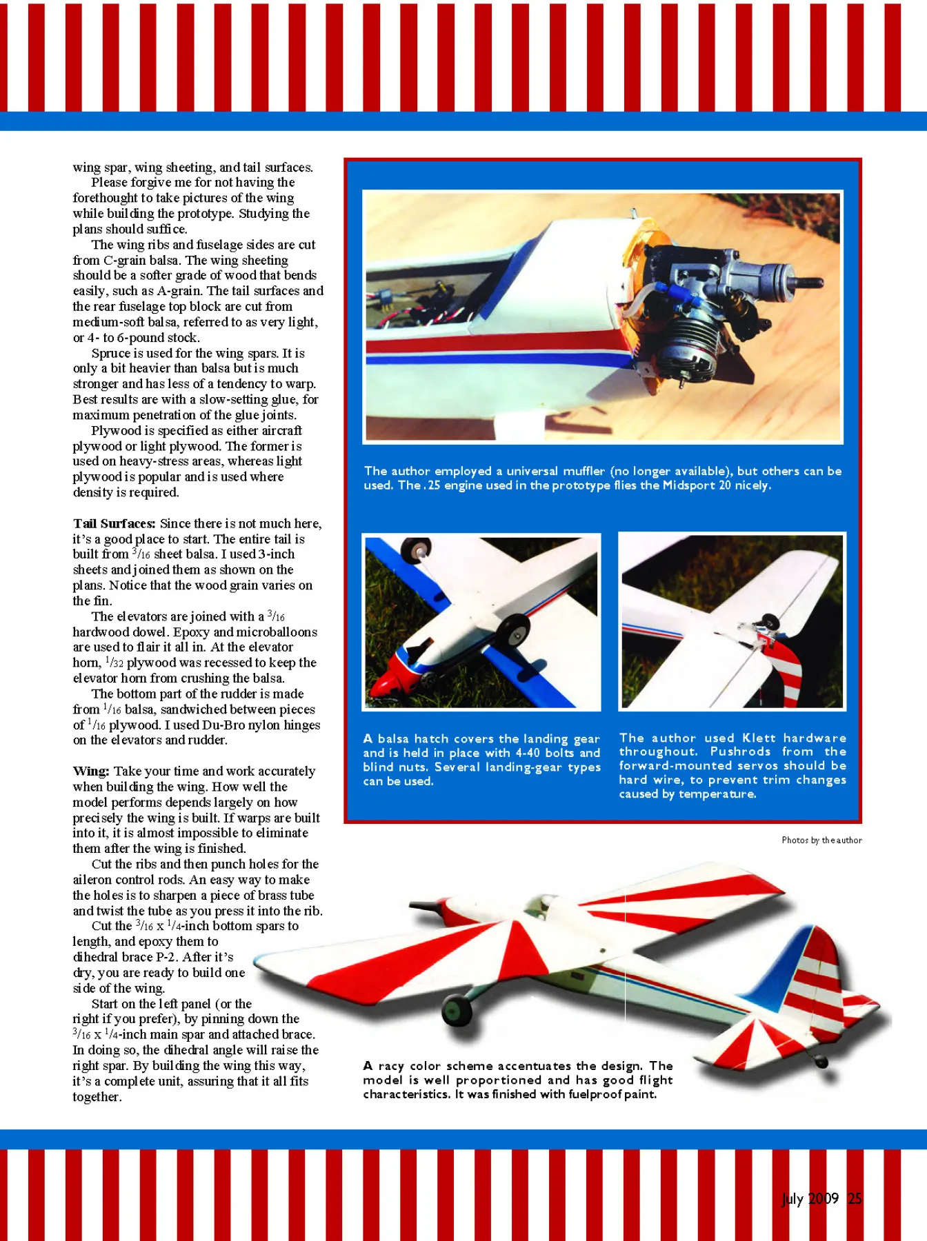
A balsa hatch covers the landing gear
and is held in place with 4-40 bolts and
blind nuts. Several landing-gear types
can be used.
The author used Klett hardware
throughout. Pushrods from the
forward-mounted servos should be
hard wire, to prevent trim changes
caused by temperature.
The author employed a universal muffler (no longer available), but others can be
used. The .25 engine used in the prototype flies the Midsport 20 nicely.
wing spar, wing sheeting, and tail surfaces.
Please forgive me for not having the
forethought to take pictures of the wing
while building the prototype. Studying the
plans should suffice.
The wing ribs and fuselage sides are cut
from C-grain balsa. The wing sheeting
should be a softer grade of wood that bends
easily, such as A-grain. The tail surfaces and
the rear fuselage top block are cut from
medium-soft balsa, referred to as very light,
or 4- to 6-pound stock.
Spruce is used for the wing spars. It is
only a bit heavier than balsa but is much
stronger and has less of a tendency to warp.
Best results are with a slow-setting glue, for
maximum penetration of the glue joints.
Plywood is specified as either aircraft
plywood or light plywood. The former is
used on heavy-stress areas, whereas light
plywood is popular and is used where
density is required.
Tail Surfaces: Since there is not much here,
it’s a good place to start. The entire tail is
built from 3/16 sheet balsa. I used 3-inch
sheets and joined them as shown on the
plans. Notice that the wood grain varies on
the fin.
The elevators are joined with a 3/16
hardwood dowel. Epoxy and microballoons
are used to flair it all in. At the elevator
horn, 1/32 plywood was recessed to keep the
elevator horn from crushing the balsa.
The bottom part of the rudder is made
from 1/16 balsa, sandwiched between pieces
of 1/16 plywood. I used Du-Bro nylon hinges
on the elevators and rudder.
Wing: Take your time and work accurately
when building the wing. How well the
model performs depends largely on how
precisely the wing is built. If warps are built
into it, it is almost impossible to eliminate
them after the wing is finished.
Cut the ribs and then punch holes for the
aileron control rods. An easy way to make
the holes is to sharpen a piece of brass tube
and twist the tube as you press it into the rib.
Cut the 3/16 x 1/4-inch bottom spars to
length, and epoxy them to
dihedral brace P-2. After it’s
dry, you are ready to build one
side of the wing.
Start on the left panel (or the
right if you prefer), by pinning down the
3/16 x 1/4-inch main spar and attached brace.
In doing so, the dihedral angle will raise the
right spar. By building the wing this way,
it’s a complete unit, assuring that it all fits
together.
A racy color scheme accentuates the design. The
model is well proportioned and has good flight
characteristics. It was finished with fuelproof paint.
07sig1.QXD 5/22/09 12:36 PM Page 25
26 MODEL AVIATION
Fuselage sides are cut from 3/32 balsa sheet with 1/32 plywood used
as nose doublers. At the landing gear area, 1/8 plywood was added
with 1/4 triangular stock.
On the finished basic fuselage structure, the firewall (F-1) has been
glued in place and holes have been drilled for the engine mount and
4-40 blind nuts. The rear top deck is temporarily in place.
Type: RC sport
Skill level: Beginner builder, intermediate pilot
Wingspan: 55 inches
Construction: Balsa and plywood
Finish: Builder’s choice (author used silk and paint)
Other: 4-ounce fuel tank, four-channel radio with four standard servos, 2-inch spinner, 2.5-
inch main wheels, aluminum landing gear, clear bubble canopy
Wing area: 497 square inches
Length: 37.75 inches
Weight: 4 pounds
Engine/motor: .25-.32 two-stroke/500 watts
The tail surfaces are cut from lightweight 3/16 balsa sheet. Notice
the grain direction on the fin. Thin plywood is glued where the
rudder horn and tail-wheel bracket will mount.
07sig1.QXD 5/22/09 12:37 PM Page 26
July 2009 27
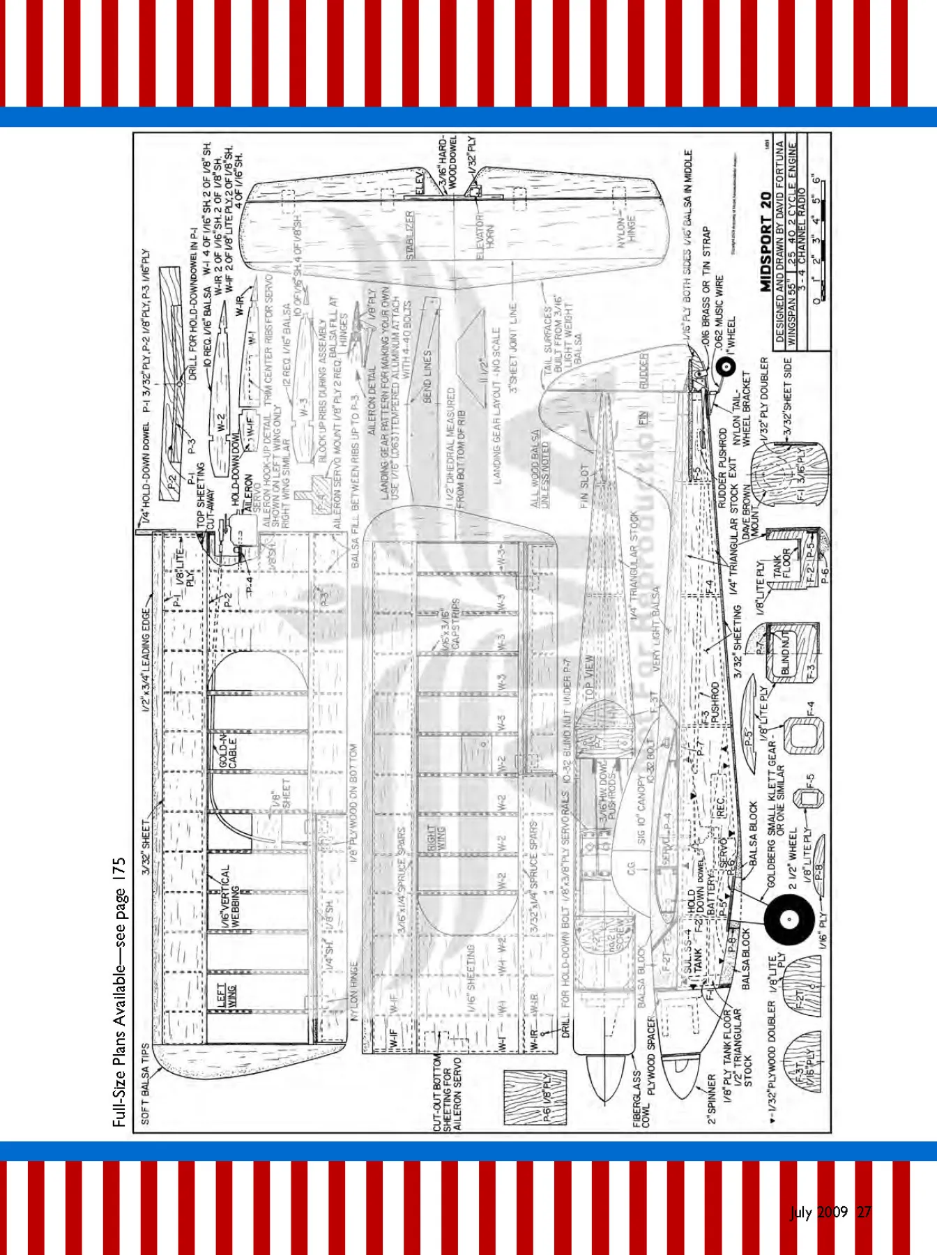
Full-Size Plans Available—see page 175
07sig1.QXD 5/22/09 12:54 PM Page 27
Now you can glue the ribs in place. Pin a
1/8-inch square fixture strip under the LE
portion of the ribs. You can add a similar
strip at the TE if needed.
Glue in ribs, starting with W-2 and W-3.
The plans show rib W-3 in two pieces, but it
is easier to glue it in one piece and cut it later
for the ailerons, which is what I did. At this
point, the ribs are glued only to the 3/16 x 1/4-
inch main bottom spar. As you are gluing in
the ribs, lay a straightedge across the ribs to
make sure they are aligned.
Glue in rib sections W-1, checking
alignment against the other ribs. Add front rib
sections W-1F. Cut out the center ribs for the
hold-down dowel. Epoxy the dowel in, and
then add front wing brace P-1 and the 3/32-
inch LE. Now you can add the front and rear
top spars.
After the wing panel is dry, remove it
from the building board. Block the left wing
panel up and pin the right main spar down.
The right wing panel is built onto the left
panel.
Once complete, add the bottom 3/32 x 1/4-
inch rear spar, wing brace P-3, and rib
sections W-1R. Sheet the bottom of the
wing and cut out the ailerons. There will be
a 3/16-inch gap between the aileron sheeting
and rear wing spar. Add a 1/8 balsa TE
behind the rear spar at the aileron. Also add
balsa between the rear spars where hinges
are to go.
Trim aileron ribs for the LE. Glue the LE
28 MODEL AVIATION
FREE
SHIPPING
“EDF Exclusives”
From Fan Jets USA
• Wide selection of composite
and foam jets, average top
speeds 100 MPH
• Models with speeds up to
120 MPH as equipped,
before customization
• Exclusive Jetapult™
“Hands Free” Launcher
• Exclusive Jet Installation
Service for Single and
Twin Engines!
• Parts and accessories
Or, call toll-free
877-538-3268
e-mail [email protected]
Visit our website to view
all models, special prices,
and on-line ordering.
www.fanjetsusa.com
Copyright 2009 Fan Jets USA
OUR MISSION: EDF JETS
Jetapult™
Launching System
$59.99
F-16
$178.99
Sapac L-39
$284.99
Brushless motor integrated into fan
unit. Unrivaled performance for a
70mm class fan unit.
$199.99
Also, a wide selection of
planes at great prices
“THE STORM” IS HERE!
P-51 Mustang
$139.99
in place and add plywood for the aileron
horn mount.
To mount the aileron servo, cut the
bottom sheeting out as shown. The servo
mounts to P-4, which should be cut to fit
your servo.
Route Sullivan Products Gold-N-Cable
through the wing with a threaded coupler
used on the aileron end. Use an aileron
connector and Du-Bro Ball Link Dual
Take-Off on the servo end.
Once it’s hooked up and working
properly, add the top wing sheeting and
then the 1/2 x 3/4-inch LE and wingtips.
Wingtips are made from lightweight balsa
and can be carved out on the inside to
reduce weight.
Plans show 1/16-inch vertical webbing
between the wing ribs. I did not add vertical
webbing on my model, but my flying
method doesn’t put a lot of stress on the
wing. If you used a larger engine or like to
fly on the wild side, it’s best to add vertical
webbing.
Add wing capstrips. These should be
medium-soft balsa, which bends easily.
After you have sanded down the wing
and shaped the LE, glue 2-inch-wide
fiberglass tape along the center-section as
reinforcement. You can put this down with
15-minute epoxy or slow cyanoacrylate.
Balsa, which makes the top part of the
fuselage, is glued on the wing centersection
at a later time.
Fuselage: Cut the sides from 3/32 balsa.
Make the right side 3/32 inch shorter at the
nose, to provide right thrust.
Cut 1/32 plywood nose doublers and glue
them in place. The doublers are glued
inside the 1/4 triangular stock, so you must
leave a 1/4-inch border for this. Be sure to
make a left and right side.
Bevel the 1/4 triangular stock at the rear,
using the top view, and then glue it in
place. Notice that the triangular stock
extends past the sides at the bottom, just
behind the landing gear. This is trimmed
flush with the side after gluing in place.
Mark the fuselage formers’ location on
the fuselage sides, and cut out for landinggear
plate P-6, stabilizer opening, and
pushrod exits at the rear. Glue in the 1/8
light-plywood doubler P-5 around the
landing-gear cutout. Glue balsa in the tail,
inside the triangular stock, and sand to
shape.
All fuselage formers are cut from
plywood. F-1 is 3/16 plywood, and the
remaining are made from 1/8 light plywood.
Glue F-2 and F-3 to one side of the
fuselage and ensure that they are 90° to the
side. When dry, add the other side.
Before epoxying in F-1, decide what
size engine you will use and how you will
mount it. I employed a Dave Brown
Products mount and a .25 engine. With this
setup, I added a 3/8 plywood spacer behind
the mount. Or you can use a long mount in
this scenario.
I chose a Du-Bro universal muffler,
extending out the cowl bottom. It is no
07sig1.QXD 5/22/09 12:54 PM Page 28
30 MODEL AVIATION
longer available, but other muffler types are
suitable.
If using a larger engine or a sport
muffler, you might need to mount the power
plant upright for muffler clearance. Decide
that before you install the mount and blind
nuts in F-1.
Epoxy F-1 in place and add 1/2 triangular
stock behind it. Tightly secure the fuselage
sides with masking tape or rubber bands
until the epoxy is completely cured.
Mount the landing gear in place. There
are several options for gear; the best is to
buy one ready-made, which is what I did. I
used a Klett small landing gear (item 255)
from Carl Goldberg Products. I selected it
for its scale looks, and since it’s composite,
it takes paint well.
Sig offers a number of aluminum landing
gear. The Kadet Jr. type (item RP-BA-246)
is close in size to the Klett variety.
If you decide to bend your own gear,
make it from .063 (1/16 inch) tempered
aluminum—not the soft kind found in
hobby stores. When bending the aluminum,
heat it with a propane torch; otherwise, it
may fracture at the bending point. Do not
hold the torch on one spot; overheating can
also cause the aluminum to crack.
With the landing gear mounted on P-6,
make sure it fits in the fuselage. I had to
slightly carve out along F-2 and the fuselage
sides to clear the blind nuts. However, that
may be unnecessary, depending on what
landing gear you use. Epoxy P-6 in place.
Cut the fuel-tank floor from 1/8 light
plywood and glue it in place. I used a
Sullivan 4-ounce slant tank.
Fuel-proof the fuel-tank compartment
with a coat of epoxy glue. If you use 15- or
30-minute epoxy, it can be thinned with
acetone, if necessary, for brushing.
Make the front bottom section from a
balsa block, with P-8 glued behind it. A
removable balsa hatch covers the landing
gear so it can be easily removed, if
necessary. The hatch is held in place with 4-
40 screws and blind nuts.
Mount the tail-wheel bracket to a piece
of 1/8 plywood that is recessed in the
fuselage so that it fits flush with the bottom
sheeting. Bend the tail-wheel gear from 1/16-
inch-diameter (.063) music wire, and secure
it to the rudder with a metal strap.
Fit the wing in place by gluing scrap
balsa under its front and rear section, to
make the wing saddle. This should be
accurately sanded to shape using a template,
since it will establish the wing incidence
angle.
Set the wing and stabilizer in place and
check alignment against each other. When
everything looks good, glue the stabilizer in
place.
Remove the wing and fit the rear holddown
plate, P-7, in place but do not glue it.
You will need to trim the 1/4 triangular stock
away so that P-7 fits flush against the
fuselage sides.
Add balsa on top of P-7 and sand it to
match the wing contour, and then mark and
drill holes for 10-32 wing bolts. Those can
be held in place with blind nuts or threaded
hardwood blocks glued under P-7. Epoxy P-
7 in place.
Cut the front top block to its
approximate shape, and then carve it out on
the inside, as necessary, to clear the fuel
tank. Tack-glue the block in place and sand
to shape.
To make the block removable for fueltank
access, mount a blind nut to a piece of
plywood that is recessed in the block. A 4-
40 bolt goes through the top of the plywood
spacer and screws through the blind nut in
back of F-1 and into the blind nut in the
block.
The rear section of the block is held
down by No. 2 screws, recessed in the block
to clear the wing. Insert small pieces of 3/32
plywood in the block at the screw holes to
keep the screws from crushing the balsa
when they are tightened.
With the front block screwed in place,
glue in F-2. Locate and drill a 1/4-inch hole
for the hold-down dowel.
Before installing the pushrods, set the fin
in place. Small balsa blocks go on both
sides of it, extending up to F-5. With the fin
in place, check alignment and glue the
blocks only to the fuselage. These blocks
are sanded and shaped later, along with the
rest of the fuselage top deck, and then the
fin is glued in place.
For control rods, you can use one of the
07sig1.QXD 5/22/09 12:54 PM Page 30
32 MODEL AVIATION
popular types, such as Du-Bro Lazer
Pushrods or Sullivan Gold-N-Rods. When
using these, glue supports on the fuselage
formers and epoxy the rods in.
I made pushrods from 3/16-inch-diameter
dowel rods. Make a 5-64 hole 3/4 inch from
the end of the dowel. Make a 90° bend 5/16
inch from the end of a 2-56 rod, and insert
this end in the drilled hole. Secure the metal
rod to the dowel by wrapping it tightly with
strong cord, such as 1/2A flying-line thread,
and coating it with epoxy or cyanoacrylate.
Servos are mounted on 1/8 x 3/8 plywood
rails, glued to the fuselage sides, with 3/16 x
1/4 balsa strips glued under the rails. Servos
might need to be shifted slightly for balance.
Also, make sure they don’t interfere with the
aileron servo.
With the rudder and elevator in place,
check controls for smooth operation and
make certain that no binding occurs. For
control throw, I used 1/2 inch on the rudder,
1/2 inch up and 1/4 inch down on the elevator,
and 1/2 inch up and 3/8 inch down on the
aileron.
Sheet the rear bottom section of the
fuselage, and glue the rear top block in
place. Use extremely light balsa for it. You
can carve the inside portion of the block to a
1/4 inch wall thickness to reduce weight.
Glue F-3T in place.
Mount the wing, glue balsa on top of the
wing, as shown, and open the wing-bolt
holes. Now you can shape and sand together
the entire top deck and wing center-section.
Glue the fin in place.
Cowl: You can make a simple, open-ended
sport cowl by gluing 1/4 balsa sheet to the
fuselage sides, leaving the top and bottom
open. This setup works best for an upright
engine installation.
I made a fiberglass cowl by using the
balloon method. To do this, make a cowl
plug from sheet and block balsa. Sand the
structure to shape, leaving it 1/32 inch
undersized.
Glue a 3/8-inch-diameter dowel that is
approximately 3 inches long on the back of
the cowl. Hold the cowl in place by putting
the dowel in a vise.
Drape Saran Wrap over the cowl, and
follow that with heavyweight fiberglass
cloth. The cloth is held in place with
thumbtacks pushed into the back of the
cowl.
Coat the fiberglass cloth with slowdrying
(15- or 30-minute) epoxy. Inflate a
balloon and push it over the cowl while
slowly letting the air out. The balloon should
be large enough that it doesn’t burst when
it’s forced over the cowl. You should have
more than one balloon for this process.
Once the balloon is over the cowl, let it
set overnight. Then peel off the balloon and
add another layer of fiberglass cloth. Sand
the cowl and fuselage together so they match
up.
Covering and Finishing: Fill any
imperfections with lightweight spackling
paste. Make fillets with epoxy and
microballoons. Carefully sand the model
with 320-grit paper, and apply the covering
of your choice.
I covered the fuselage and tail with
medium-weight silkspan and the wing with
Dave Brown Products Skyloft. This bonded
nylon material is inexpensive, lightweight,
and extraordinarily strong.
My finishing method is to apply two
coats of clear dope to the entire model,
followed by a light sanding. Then I dope the
covering in place and trim it.
I brush on two coats of clear dope,
followed by four coats of a dope/talcum
powder mix (or your can use sanding sealer).
After that has dried for several days, I sand it
with 320- and 400-grit sandpaper until most
of it is removed.
I epoxy the canopy in place, tape it, and
then spray the model with colored dope.
This gives the Midsport a lightweight, scaletype
finish that is durable and easy to touch
up.
Flying: Epoxy the control surfaces in place
and check the controls. Make sure they
move in the correct direction. The model
should balance on the main spar, with the
nose level or pointing slightly down.
Do a radio range check and inspect the
model carefully. Many crashes are caused by
small things that were overlooked.
If you have flown several sport models,
the Midsport 20 should present no problems.
Make the first flights on a calm day. If the
model is out of trim, wind will only make
things worse.
Everything went smoothly on the first
flight; only a small trim adjustment was
needed. I don’t owe that to luck, but to
thoroughly checking for warps and
alignment during construction and making
sure that the balance was right and that
everything worked correctly before flying.
Many happy flights! MA
David Fortuna
5065 Wards Rd.
Evington VA 24550
Sources:
Du-Bro
(800) 848-9411
www.dubro.com
Carl Goldberg Products:
Great Planes Model Distributors
(800) 637-7660
carlgoldbergproducts.com
Sullivan Products
(410) 732-3500
www.sullivanproducts.com
Sig Manufacturing
(641) 623-5154
www.sigmfg.com
Dave Brown Products
(513) 738-1576
www.dbproducts.com
07sig1.QXD 5/22/09 12:38 PM Page 32
Edition: Model Aviation - 2009/07
Page Numbers: 24,25,26,27,28,30,32
Edition: Model Aviation - 2009/07
Page Numbers: 24,25,26,27,28,30,32
THE MIDSPORT 20 design was inspired
by midget Goodyear racers. The first
Goodyear Race was held at the Cleveland
National Air Races in 1948. In 1964, the
races were moved to the Reno National Air
Races, which is still going strong today.
July 2009 25
Photos by the author
A balsa hatch covers the landing gear
and is held in place with 4-40 bolts and
blind nuts. Several landing-gear types
can be used.
The author used Klett hardware
throughout. Pushrods from the
forward-mounted servos should be
hard wire, to prevent trim changes
caused by temperature.
The author employed a universal muffler (no longer available), but others can be
used. The .25 engine used in the prototype flies the Midsport 20 nicely.
wing spar, wing sheeting, and tail surfaces.
Please forgive me for not having the
forethought to take pictures of the wing
while building the prototype. Studying the
plans should suffice.
The wing ribs and fuselage sides are cut
from C-grain balsa. The wing sheeting
should be a softer grade of wood that bends
easily, such as A-grain. The tail surfaces and
the rear fuselage top block are cut from
medium-soft balsa, referred to as very light,
or 4- to 6-pound stock.
Spruce is used for the wing spars. It is
only a bit heavier than balsa but is much
stronger and has less of a tendency to warp.
Best results are with a slow-setting glue, for
maximum penetration of the glue joints.
Plywood is specified as either aircraft
plywood or light plywood. The former is
used on heavy-stress areas, whereas light
plywood is popular and is used where
density is required.
Tail Surfaces: Since there is not much here,
it’s a good place to start. The entire tail is
built from 3/16 sheet balsa. I used 3-inch
sheets and joined them as shown on the
plans. Notice that the wood grain varies on
the fin.
The elevators are joined with a 3/16
hardwood dowel. Epoxy and microballoons
are used to flair it all in. At the elevator
horn, 1/32 plywood was recessed to keep the
elevator horn from crushing the balsa.
The bottom part of the rudder is made
from 1/16 balsa, sandwiched between pieces
of 1/16 plywood. I used Du-Bro nylon hinges
on the elevators and rudder.
Wing: Take your time and work accurately
when building the wing. How well the
model performs depends largely on how
precisely the wing is built. If warps are built
into it, it is almost impossible to eliminate
them after the wing is finished.
Cut the ribs and then punch holes for the
aileron control rods. An easy way to make
the holes is to sharpen a piece of brass tube
and twist the tube as you press it into the rib.
Cut the 3/16 x 1/4-inch bottom spars to
length, and epoxy them to
dihedral brace P-2. After it’s
dry, you are ready to build one
side of the wing.
Start on the left panel (or the
right if you prefer), by pinning down the
3/16 x 1/4-inch main spar and attached brace.
In doing so, the dihedral angle will raise the
right spar. By building the wing this way,
it’s a complete unit, assuring that it all fits
together.
A racy color scheme accentuates the design. The
model is well proportioned and has good flight
characteristics. It was finished with fuelproof paint.
07sig1.QXD 5/22/09 12:36 PM Page 25
26 MODEL AVIATION
Fuselage sides are cut from 3/32 balsa sheet with 1/32 plywood used
as nose doublers. At the landing gear area, 1/8 plywood was added
with 1/4 triangular stock.
On the finished basic fuselage structure, the firewall (F-1) has been
glued in place and holes have been drilled for the engine mount and
4-40 blind nuts. The rear top deck is temporarily in place.
Type: RC sport
Skill level: Beginner builder, intermediate pilot
Wingspan: 55 inches
Construction: Balsa and plywood
Finish: Builder’s choice (author used silk and paint)
Other: 4-ounce fuel tank, four-channel radio with four standard servos, 2-inch spinner, 2.5-
inch main wheels, aluminum landing gear, clear bubble canopy
Wing area: 497 square inches
Length: 37.75 inches
Weight: 4 pounds
Engine/motor: .25-.32 two-stroke/500 watts
The tail surfaces are cut from lightweight 3/16 balsa sheet. Notice
the grain direction on the fin. Thin plywood is glued where the
rudder horn and tail-wheel bracket will mount.
07sig1.QXD 5/22/09 12:37 PM Page 26
July 2009 27
Full-Size Plans Available—see page 175
07sig1.QXD 5/22/09 12:54 PM Page 27
Now you can glue the ribs in place. Pin a
1/8-inch square fixture strip under the LE
portion of the ribs. You can add a similar
strip at the TE if needed.
Glue in ribs, starting with W-2 and W-3.
The plans show rib W-3 in two pieces, but it
is easier to glue it in one piece and cut it later
for the ailerons, which is what I did. At this
point, the ribs are glued only to the 3/16 x 1/4-
inch main bottom spar. As you are gluing in
the ribs, lay a straightedge across the ribs to
make sure they are aligned.
Glue in rib sections W-1, checking
alignment against the other ribs. Add front rib
sections W-1F. Cut out the center ribs for the
hold-down dowel. Epoxy the dowel in, and
then add front wing brace P-1 and the 3/32-
inch LE. Now you can add the front and rear
top spars.
After the wing panel is dry, remove it
from the building board. Block the left wing
panel up and pin the right main spar down.
The right wing panel is built onto the left
panel.
Once complete, add the bottom 3/32 x 1/4-
inch rear spar, wing brace P-3, and rib
sections W-1R. Sheet the bottom of the
wing and cut out the ailerons. There will be
a 3/16-inch gap between the aileron sheeting
and rear wing spar. Add a 1/8 balsa TE
behind the rear spar at the aileron. Also add
balsa between the rear spars where hinges
are to go.
Trim aileron ribs for the LE. Glue the LE
28 MODEL AVIATION
FREE
SHIPPING
“EDF Exclusives”
From Fan Jets USA
• Wide selection of composite
and foam jets, average top
speeds 100 MPH
• Models with speeds up to
120 MPH as equipped,
before customization
• Exclusive Jetapult™
“Hands Free” Launcher
• Exclusive Jet Installation
Service for Single and
Twin Engines!
• Parts and accessories
Or, call toll-free
877-538-3268
e-mail [email protected]
Visit our website to view
all models, special prices,
and on-line ordering.
www.fanjetsusa.com
Copyright 2009 Fan Jets USA
OUR MISSION: EDF JETS
Jetapult™
Launching System
$59.99
F-16
$178.99
Sapac L-39
$284.99
Brushless motor integrated into fan
unit. Unrivaled performance for a
70mm class fan unit.
$199.99
Also, a wide selection of
planes at great prices
“THE STORM” IS HERE!
P-51 Mustang
$139.99
in place and add plywood for the aileron
horn mount.
To mount the aileron servo, cut the
bottom sheeting out as shown. The servo
mounts to P-4, which should be cut to fit
your servo.
Route Sullivan Products Gold-N-Cable
through the wing with a threaded coupler
used on the aileron end. Use an aileron
connector and Du-Bro Ball Link Dual
Take-Off on the servo end.
Once it’s hooked up and working
properly, add the top wing sheeting and
then the 1/2 x 3/4-inch LE and wingtips.
Wingtips are made from lightweight balsa
and can be carved out on the inside to
reduce weight.
Plans show 1/16-inch vertical webbing
between the wing ribs. I did not add vertical
webbing on my model, but my flying
method doesn’t put a lot of stress on the
wing. If you used a larger engine or like to
fly on the wild side, it’s best to add vertical
webbing.
Add wing capstrips. These should be
medium-soft balsa, which bends easily.
After you have sanded down the wing
and shaped the LE, glue 2-inch-wide
fiberglass tape along the center-section as
reinforcement. You can put this down with
15-minute epoxy or slow cyanoacrylate.
Balsa, which makes the top part of the
fuselage, is glued on the wing centersection
at a later time.
Fuselage: Cut the sides from 3/32 balsa.
Make the right side 3/32 inch shorter at the
nose, to provide right thrust.
Cut 1/32 plywood nose doublers and glue
them in place. The doublers are glued
inside the 1/4 triangular stock, so you must
leave a 1/4-inch border for this. Be sure to
make a left and right side.
Bevel the 1/4 triangular stock at the rear,
using the top view, and then glue it in
place. Notice that the triangular stock
extends past the sides at the bottom, just
behind the landing gear. This is trimmed
flush with the side after gluing in place.
Mark the fuselage formers’ location on
the fuselage sides, and cut out for landinggear
plate P-6, stabilizer opening, and
pushrod exits at the rear. Glue in the 1/8
light-plywood doubler P-5 around the
landing-gear cutout. Glue balsa in the tail,
inside the triangular stock, and sand to
shape.
All fuselage formers are cut from
plywood. F-1 is 3/16 plywood, and the
remaining are made from 1/8 light plywood.
Glue F-2 and F-3 to one side of the
fuselage and ensure that they are 90° to the
side. When dry, add the other side.
Before epoxying in F-1, decide what
size engine you will use and how you will
mount it. I employed a Dave Brown
Products mount and a .25 engine. With this
setup, I added a 3/8 plywood spacer behind
the mount. Or you can use a long mount in
this scenario.
I chose a Du-Bro universal muffler,
extending out the cowl bottom. It is no
07sig1.QXD 5/22/09 12:54 PM Page 28
30 MODEL AVIATION
longer available, but other muffler types are
suitable.
If using a larger engine or a sport
muffler, you might need to mount the power
plant upright for muffler clearance. Decide
that before you install the mount and blind
nuts in F-1.
Epoxy F-1 in place and add 1/2 triangular
stock behind it. Tightly secure the fuselage
sides with masking tape or rubber bands
until the epoxy is completely cured.
Mount the landing gear in place. There
are several options for gear; the best is to
buy one ready-made, which is what I did. I
used a Klett small landing gear (item 255)
from Carl Goldberg Products. I selected it
for its scale looks, and since it’s composite,
it takes paint well.
Sig offers a number of aluminum landing
gear. The Kadet Jr. type (item RP-BA-246)
is close in size to the Klett variety.
If you decide to bend your own gear,
make it from .063 (1/16 inch) tempered
aluminum—not the soft kind found in
hobby stores. When bending the aluminum,
heat it with a propane torch; otherwise, it
may fracture at the bending point. Do not
hold the torch on one spot; overheating can
also cause the aluminum to crack.
With the landing gear mounted on P-6,
make sure it fits in the fuselage. I had to
slightly carve out along F-2 and the fuselage
sides to clear the blind nuts. However, that
may be unnecessary, depending on what
landing gear you use. Epoxy P-6 in place.
Cut the fuel-tank floor from 1/8 light
plywood and glue it in place. I used a
Sullivan 4-ounce slant tank.
Fuel-proof the fuel-tank compartment
with a coat of epoxy glue. If you use 15- or
30-minute epoxy, it can be thinned with
acetone, if necessary, for brushing.
Make the front bottom section from a
balsa block, with P-8 glued behind it. A
removable balsa hatch covers the landing
gear so it can be easily removed, if
necessary. The hatch is held in place with 4-
40 screws and blind nuts.
Mount the tail-wheel bracket to a piece
of 1/8 plywood that is recessed in the
fuselage so that it fits flush with the bottom
sheeting. Bend the tail-wheel gear from 1/16-
inch-diameter (.063) music wire, and secure
it to the rudder with a metal strap.
Fit the wing in place by gluing scrap
balsa under its front and rear section, to
make the wing saddle. This should be
accurately sanded to shape using a template,
since it will establish the wing incidence
angle.
Set the wing and stabilizer in place and
check alignment against each other. When
everything looks good, glue the stabilizer in
place.
Remove the wing and fit the rear holddown
plate, P-7, in place but do not glue it.
You will need to trim the 1/4 triangular stock
away so that P-7 fits flush against the
fuselage sides.
Add balsa on top of P-7 and sand it to
match the wing contour, and then mark and
drill holes for 10-32 wing bolts. Those can
be held in place with blind nuts or threaded
hardwood blocks glued under P-7. Epoxy P-
7 in place.
Cut the front top block to its
approximate shape, and then carve it out on
the inside, as necessary, to clear the fuel
tank. Tack-glue the block in place and sand
to shape.
To make the block removable for fueltank
access, mount a blind nut to a piece of
plywood that is recessed in the block. A 4-
40 bolt goes through the top of the plywood
spacer and screws through the blind nut in
back of F-1 and into the blind nut in the
block.
The rear section of the block is held
down by No. 2 screws, recessed in the block
to clear the wing. Insert small pieces of 3/32
plywood in the block at the screw holes to
keep the screws from crushing the balsa
when they are tightened.
With the front block screwed in place,
glue in F-2. Locate and drill a 1/4-inch hole
for the hold-down dowel.
Before installing the pushrods, set the fin
in place. Small balsa blocks go on both
sides of it, extending up to F-5. With the fin
in place, check alignment and glue the
blocks only to the fuselage. These blocks
are sanded and shaped later, along with the
rest of the fuselage top deck, and then the
fin is glued in place.
For control rods, you can use one of the
07sig1.QXD 5/22/09 12:54 PM Page 30
32 MODEL AVIATION
popular types, such as Du-Bro Lazer
Pushrods or Sullivan Gold-N-Rods. When
using these, glue supports on the fuselage
formers and epoxy the rods in.
I made pushrods from 3/16-inch-diameter
dowel rods. Make a 5-64 hole 3/4 inch from
the end of the dowel. Make a 90° bend 5/16
inch from the end of a 2-56 rod, and insert
this end in the drilled hole. Secure the metal
rod to the dowel by wrapping it tightly with
strong cord, such as 1/2A flying-line thread,
and coating it with epoxy or cyanoacrylate.
Servos are mounted on 1/8 x 3/8 plywood
rails, glued to the fuselage sides, with 3/16 x
1/4 balsa strips glued under the rails. Servos
might need to be shifted slightly for balance.
Also, make sure they don’t interfere with the
aileron servo.
With the rudder and elevator in place,
check controls for smooth operation and
make certain that no binding occurs. For
control throw, I used 1/2 inch on the rudder,
1/2 inch up and 1/4 inch down on the elevator,
and 1/2 inch up and 3/8 inch down on the
aileron.
Sheet the rear bottom section of the
fuselage, and glue the rear top block in
place. Use extremely light balsa for it. You
can carve the inside portion of the block to a
1/4 inch wall thickness to reduce weight.
Glue F-3T in place.
Mount the wing, glue balsa on top of the
wing, as shown, and open the wing-bolt
holes. Now you can shape and sand together
the entire top deck and wing center-section.
Glue the fin in place.
Cowl: You can make a simple, open-ended
sport cowl by gluing 1/4 balsa sheet to the
fuselage sides, leaving the top and bottom
open. This setup works best for an upright
engine installation.
I made a fiberglass cowl by using the
balloon method. To do this, make a cowl
plug from sheet and block balsa. Sand the
structure to shape, leaving it 1/32 inch
undersized.
Glue a 3/8-inch-diameter dowel that is
approximately 3 inches long on the back of
the cowl. Hold the cowl in place by putting
the dowel in a vise.
Drape Saran Wrap over the cowl, and
follow that with heavyweight fiberglass
cloth. The cloth is held in place with
thumbtacks pushed into the back of the
cowl.
Coat the fiberglass cloth with slowdrying
(15- or 30-minute) epoxy. Inflate a
balloon and push it over the cowl while
slowly letting the air out. The balloon should
be large enough that it doesn’t burst when
it’s forced over the cowl. You should have
more than one balloon for this process.
Once the balloon is over the cowl, let it
set overnight. Then peel off the balloon and
add another layer of fiberglass cloth. Sand
the cowl and fuselage together so they match
up.
Covering and Finishing: Fill any
imperfections with lightweight spackling
paste. Make fillets with epoxy and
microballoons. Carefully sand the model
with 320-grit paper, and apply the covering
of your choice.
I covered the fuselage and tail with
medium-weight silkspan and the wing with
Dave Brown Products Skyloft. This bonded
nylon material is inexpensive, lightweight,
and extraordinarily strong.
My finishing method is to apply two
coats of clear dope to the entire model,
followed by a light sanding. Then I dope the
covering in place and trim it.
I brush on two coats of clear dope,
followed by four coats of a dope/talcum
powder mix (or your can use sanding sealer).
After that has dried for several days, I sand it
with 320- and 400-grit sandpaper until most
of it is removed.
I epoxy the canopy in place, tape it, and
then spray the model with colored dope.
This gives the Midsport a lightweight, scaletype
finish that is durable and easy to touch
up.
Flying: Epoxy the control surfaces in place
and check the controls. Make sure they
move in the correct direction. The model
should balance on the main spar, with the
nose level or pointing slightly down.
Do a radio range check and inspect the
model carefully. Many crashes are caused by
small things that were overlooked.
If you have flown several sport models,
the Midsport 20 should present no problems.
Make the first flights on a calm day. If the
model is out of trim, wind will only make
things worse.
Everything went smoothly on the first
flight; only a small trim adjustment was
needed. I don’t owe that to luck, but to
thoroughly checking for warps and
alignment during construction and making
sure that the balance was right and that
everything worked correctly before flying.
Many happy flights! MA
David Fortuna
5065 Wards Rd.
Evington VA 24550
Sources:
Du-Bro
(800) 848-9411
www.dubro.com
Carl Goldberg Products:
Great Planes Model Distributors
(800) 637-7660
carlgoldbergproducts.com
Sullivan Products
(410) 732-3500
www.sullivanproducts.com
Sig Manufacturing
(641) 623-5154
www.sigmfg.com
Dave Brown Products
(513) 738-1576
www.dbproducts.com
07sig1.QXD 5/22/09 12:38 PM Page 32
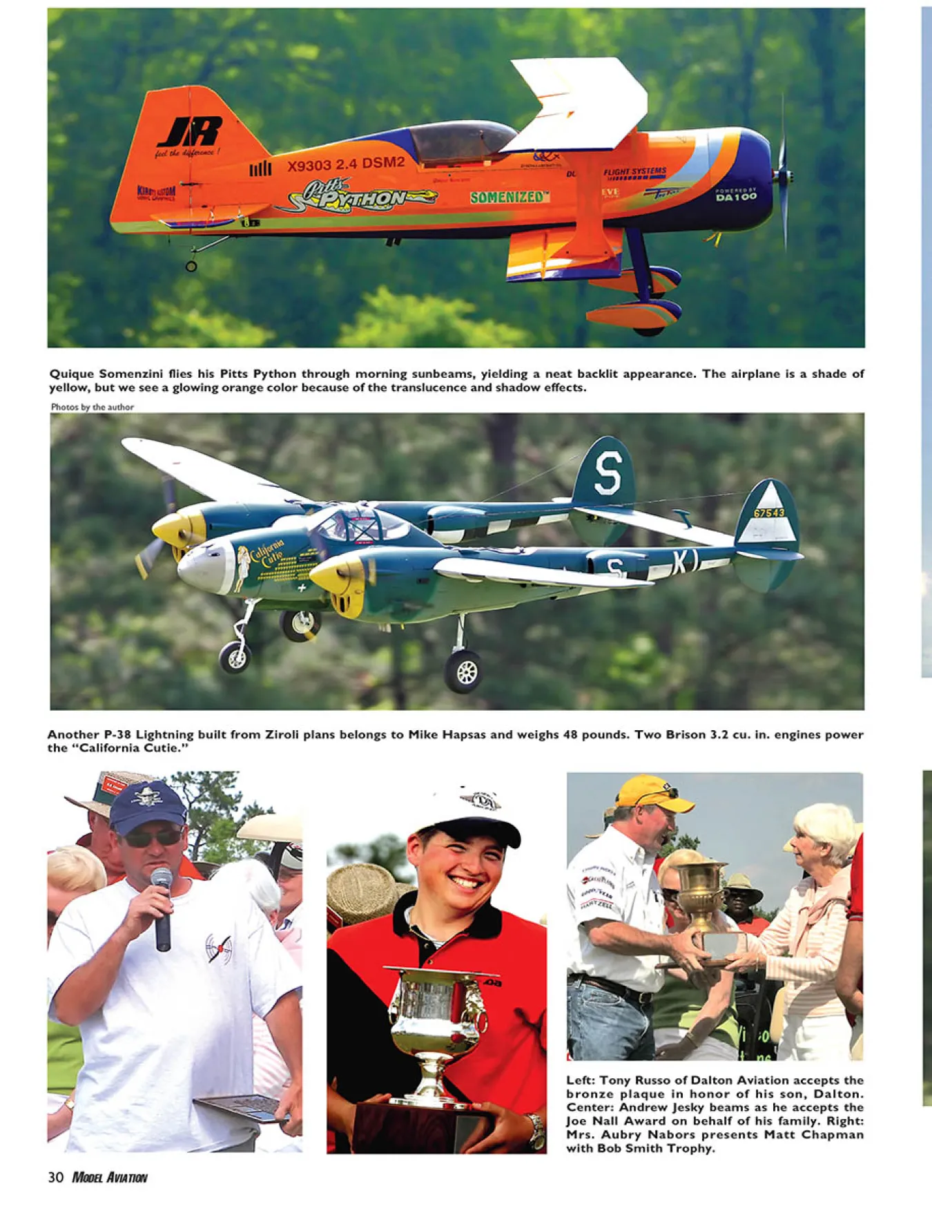

