
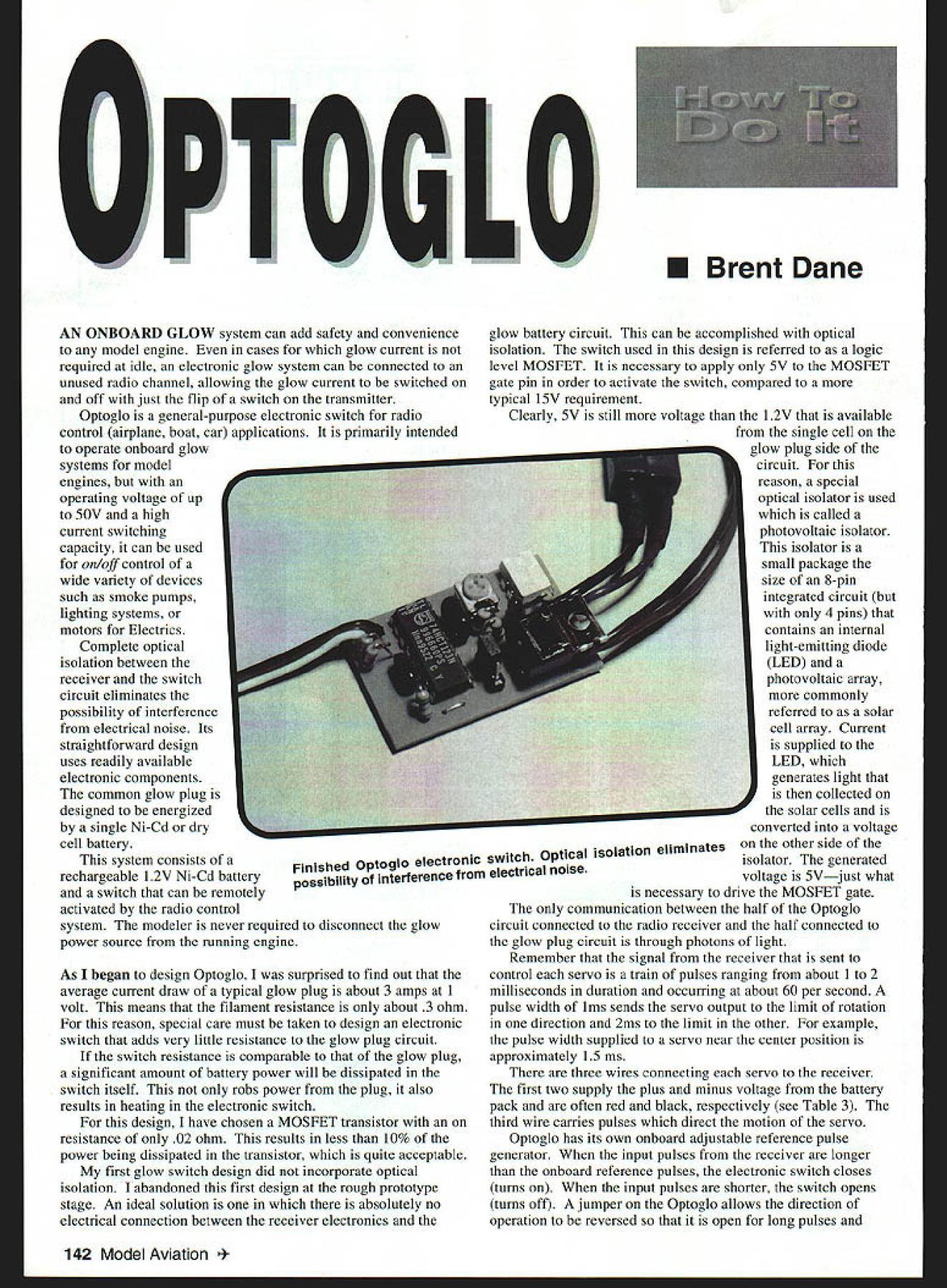
U Brent Dane ONBOARD GLOW system can add safety convenience model engine cases glow current required idle electronic glow system can connected unused radio channel allowing glow current switched off just flip switch transmitter Optoglo general-purpose electronic switch radio control airplane boat car applications primarily intended operate onboard glow systems model engines operating voltage up 50V high current switching capacity can used on/off control wide variety devices such smoke pumps lighting systems motors Electrics Complete optical isolation between receiver switch circuit eliminates possibility interference electrical noise Its straightforward design uses readily available electronic components common glow plug designed energized single Ni-Cd dry cell battery system consists rechargeable 1 2V Ni-Cd battery switch can remotely activated radio control system modeler never required disconnect glow power source running engine glow battery circuit can accomplished optical isolation switch used design referred logic level MOSFET necessary apply 5V MOSFET gate pin order activate switch compared typical iSV requirement Clearly 5V still voltage 12V available single cell glow plug side circuit reason special optical isolator used called photovoltaic isolator isolator small package size 8-pin integrated circuit 4 pins contains internal light-emitting diode LED photovoltaic array commonly referred solar cell array Current supplied LED generates light collected solar cells converted voltage Finishedon other side optoglo electronic switch Optical isolation elimisolator generated possibilitY interference electrical noisevoltage 5Vjust what necessary drive MOSFET gate communication between half Optoglo circuit connected radio receiver half connected glow plug circuit through photons light Remember signal receiver sent control servo train pulses ranging about 1 2 milliseconds duration occurring about 60 per second pulse width ims sends servo output limit rotation direction 2ms limit other example pulse width supplied servo near center position As began design Optoglo surprised find out average current draw typical glow plug about 3 amps 1 volt means filament resistance about 3 ohm reason special care must taken design electronic switch adds very little resistance glow plug circuit switch resistance comparable glow plug significant amount battery power will dissipated switch itself robs power plug also results heating electronic switch design have chosen MOSFET transistor resistance 02 ohm results less 10% power being dissipated transistor quite acceptable first glow switch design did incorporate optical isolation abandoned first design rough prototype stage An ideal solution absolutely no electrical connection between receiver electronics approximately 15 ins three wires connecting servo receiver first two supply plus minus voltage battery pack often red black respectively see Table 3 third wire carries pulses direct motion servo Optoglo has its own onboard adjustable reference pulse generator input pulses receiver longer onboard reference pulses electronic switch closes turns input pulses shorter switch opens turns off jumper Optoglo allows direction operation reversed open long pulses 142 Model Aviation * Graphic Design Jill Ann Cavanaugh closed short pulses jumper therefore functions way similar servo reversing switch Figure 2 shows electronic schematic Optoglo set point on/off changed adjusting potentiometer R4 R4 capacitor C2 determine reference pulse duration outputs pin 5 pin 12 _________ integrated circuit IC i have reversed polarity Moving jumper J2 applies _____ output either pin 5 pin 12 optical isolator IC2 Notice link between power switch side circuit side connected receiver through optical isolator red LED Dl lights indicate voltage being applied optical isolator closing high power MOSFET switch Ql D2 catch diode placed across device being powered Optoglo switch inductive loads such relay motor windings de energized produce voltage spike can cause erratic shut off characteristics catch diode suppresses possible spike Note schematic illustrates connections glow plug glow battery glow battery can replaced DC voltage source up 50V glow plug can wide range electrically powered devices CONSTRUCTION Table 1 complete parts list Optoglo catalog part numbers Digi-Key Electronics Figure 3 2X scaled pattern printed circuit board best way make board product called Press-n-Peel 2a blue plastic film can run through conventional photocopy machine printed onto directly laser printer Following instructions supplied film image Figure 3 should copied onto dull side ironed onto copper clad board such Radio Shack 276-1499 experimenting best temperature find useful securely tape film board along edge can carefully peel back small portion test adhesion pattern board transfer incomplete film let C B ng codes Table 3 0 input receiver ceiver battery R2 4 ---I215 314 413 512 611 7 10 Cl 8 9 R3 Cl R1 set point adjustment j/R4 ~2reversing 7indicator glow plug other device FIGURE 2 # parts Description Table 1 Digi-Key part number 1W resistor 220Q220QBK-ND 1W resistor 1k10KQBK-ND 2W resistor 47k47KQBK-ND 2W resistor lM1 0MQB K-ND 1100k rotary potentiometerD4AA 15-ND 1 2logic level power MOSFETIRLZ44N-ND 1polyester film capacitor 00561tFP4590-ND 1polyester film capacitor 0lgFP4593-ND 1red LED diffuse lensP363-ND 1600V silicon diode1N4005CT-ND 1dual retriggerable monostablemultivibrator MM74HC123AN-ND 15V photovoltaic isolatorPV15050-ND 13 pin square headerS 1011-03-ND 1shorting jumperS9002-ND December 1998 143 0 0 0 -I 0 FIGURE 3 electronic components required build Optoglo parts Digi-Key Table 1 shows complete list ] Receiver wiring harness see Table 3 color codes VB V 4 k 4 Optional second MOSFET~ 02 bend Glow battery Glow plug lea / dsy Optional horizontal mountingstriped end configuration single MOSFET JxdownforD2 side view FIGURE 5 Table 2 yellow purple orange* yellow purple orange brown black green rotary trim potentiometer 104 red red brown brown black red brown black green Transistors Qi IRLZ44 Logic level power MOSFET Q2 IRLZ44 Optional MOSFET Capacitors Cl0056gF C20lgF*** Diodes Dl redLED D21N4005 Integrated circuits ICL CD74123E 1C2 PV15050 * The last resistor color band gold 5% resistors ** 0056gF capacitor labeled 563 0lgF capacitor labeled 104 back down additional pressure used higher temperature After successful image transfer board etched solution ferric chloride Radio Shack 276-1535 30-60 minutes until unwanted copper gone particular blank board two-sided copper will completely removed back side After etching mounting holes should drilled #65 drill bit copper surrounding hole location accurately guides drilling Slightly larger holes will required MOSFET pins glow plug battery wires smallest possible holes should drilled case Figure 4 photograph complete set electronic components Figure 5 shows schematic installation components onto board should inserted side opposite copper circuit pattern resistors should mounted vertically Jumper J2 simply made leftover piece resistor lead Pay special attention Id 1C2 Dl D2 Ql well optional Q2 since direction installed very important Notice LED Dl has small flat spot should oriented shown figure indicator LED can also placed extension wires locate easily visible location airplane such cockpit area Diode D2 should installed striped end facing down Notice MOSFET QI can installed standing up its base flush circuit board leads can bent allowing folded over horizontally reducing overall height Optoglo latter case illustrated Figure 1 tab MOSFET may contact top lead D2 problem since transistor tab diode lead same voltage high current applications optional MOSFET Q2 can installed second board position both transistors standing position Carefully solder installed components copper circuit pattern taking care avoid solder bridges across gaps between traces extremely important use good quality resin-core electronics-grade solder brighten copper traces fine steel wool Scotch-Brite pad before starting excess resin left soldering should removed solvent such lacquer thinner epoxy brush bristles cut back receiver lead compatible radio system can purchased local hobby shop could use wiring harness worn out damaged servo Table 3 summarizes wire color codes typically used some common radio systems Using Figure 5 carefully attach leads according chart 144 Model Aviation al C Resistors Ri47k R247k R3iM R4100k R5220 R61k R7iM Table 3 ManufacturerNegative voltage APositive voltage BSignal C Airtronics/Sanwablack center wireblack red stripeblack Futabablackred center wirewhite Hitec/RCDblackred center wireyellow JRbrownred center wireorange KO Propoblackred center wireblue Kyosho/ulsarblackred center wireyellow Tower Hobbiesblackred center wirewhite NO OCR TEXT Airtronics users should cautioned V V- wires reversed servo harness Futaba JR RCD radio systems Since Airtronics harness has two wires same color black carefully note denoted center wire Table 3 Installation The finished circuit weighs about /2 ounce complete onboard system wiring sub-C battery weighs four ounces setup shown battery glow plug in-line connectors gold plated Ultra Plugs made WS Dean available through hobby retailers Tower Hobbies part #WSDM300 1 stainless steel glow plug connector manufactured McDaniel RIC McDaniel R/C #448 small circular lug should attached engine case An extra electrical lead installed sub-C battery charging terminated Deans two-pin connector Tower Hobbies part #WSDM3002 installing in-line connectors sure place female half connector battery side battery wiring harness circuit side glow plug wiring harness reduces risk short circuit plugs connected Great care should taken hooking up battery installing backwards will quickly damage MOSFET switch simplified wiring schematic single glow plug system shown Figure 7a Care should taken choosing wire size used connect glow battery glow plug connector Optoglo completed onboard glow system including 12V Ni-Cd battery glow plug connector circuit 20-gauge copper wire has resistance 00085 ohms/inch up 24 total inches wire can included both harnesses before resistance wire will have resistance equal MOSFET switch total length both wiring harnesses should kept short possible 24 inches wire required 18-gauge smaller number means bigger wire should used avoid undesirable voltage drop harnesses using Optoglo power two glow plugs twin-cylinder engine two possible connection schemes shown Figures 7b c parallel scheme Figure 7b negative wire attached engine case positive lead attached both glow plugs two plugs parallel draw twice current single plug recommended two batteries parallel used power source Figure 7c shows alternate series connection scheme case positive wire attached glow plug negative wire other glow plug electrical current through Optoglo series wiring same single glow plug twice voltage required therefore two batteries series used advantage parallel wiring scheme increased reliability plug fails flight other plug will still light providing best chance keeping engine running idle However some prefer series wiring scheme plug does fail neither plug will light preventing modeler inadvertently starting engine ground cylinder final consideration charging glow battery Since generally advisable charge two Ni-Cd cells parallel should theoretically removed circuit recharging series scheme batteries can simply charged place believe series scheme may offer few advantages easier wiring job overall three cylinders parallel arrangement possible wiring scheme since plug connected common engine case Optoglo can handle up four plugs installing second MOSFET available location board two ways connect Optoglo circuit radio control receiver first connect circuit throttle servo channel using Y-harness jumper Ji should placed position lights glow plug throttle position below set point near idle potentiometer R4 should adjusted glow plug comes desired throttle setting observing indicator LED Remember LED shows electronic switch closed necessarily plug glowing indicator Tests using Optoglo onloff controller Speed 400 Electric motor Note two MOSFETs circuit board 146 Model Aviation ors 1/e-scale Pica Cessna 182 onboard glow connector place Onlofl set point easily adjusted will light whether glow battery properly charged plug burned out second hookup option connect Optoglo separate receiver channel Electronic mixing receiver can used slave channel throttle servo channel preferred setup computer radio mixing can deactivated desired glow power can applied needed flip switch glow channel Sliding finished circuit short length 1 25-inch-diameter heat-shrink tubing provides protection circuit careful overheat circuit shrinking set access holes can cut through covering allow set point adjustments move reversing jumper circuit connected separate receiver channel described earlier access adjustments may necessary since can accomplished receiver programming like wrap finished circuit layer x foam held couple rubber bands shield against engine vibration Optoglo can used on/off switch variety devices operating battery voltages up SOy Optoglo can easily handle 5-6 amps current single MOSFET transistor installed no heatsinking required current handling can doubled adding additional optional MOSFET aggressive cooling added attaching finned aluminum heat sinks MOSFET devices rated continuous current up 40 amps Optoglo can also used small inexpensive switch increasingly popular Speed 400 similar Electric motors controlling Electric motor very important reversing jumper always placed position nearest edge circuit board motor doesnt start transmitter turned off before receiver t Dane 678 Crane Ave Livermore CA 94550 Sources Digi-Key Corporation 701 Brooks Ave South Thief River Falls MN 56701-0677 Tel 800 344-4539 Press-n-Peel manufactured Techniks can ordered Electronics Corp VanNuys CA 91411 Tel 818 997-1806 Etched printed circuit board Available author send check money order $10 per board complete unassembled kit wiring harnesses battery can obtained $25 includes postage handling Add additional $5 second MOSFET transistor applications requiring six amps current December 1998 147 NEW LASER PLAN PACS Dont pay big bucks wwl kits top quality plans laser cut parts available 1/4 Scale0rt 84 Span Plans $2500 FG Cowl $2500 Laser cut parts $6500 1/5th Scale Plans $35 00 Laser Cut parts $7500 Plans $25 00 Laser Cut partS $7500 t/4 scale ALBATROS OVA Plans $3600 Laser parts $7500 1/6th Scale pan PLANS $2600 Laser cut parts $6500 1/4 Scale Maey mareSESA PLANS $3500 Laser Pacs availableLaser parts $15000 SHIPPING AD $500 TO PLANS ORDER $800 TO LASER PAC BEST IN SCALE CATALOG $700 POST PAID BOB HOLMAN PLANS PO BOX 741 SAM BERNARDINO CA 92402 909 885 3959 FAX 909 889 9307 Kestrel 2M has introduction larger yen Kestrel lIju wiin arger greater performance ta increase wings speed r wingloading planform ate breakthrough sailplane NSP w s I c o in
Edition: Model Aviation - 1998/12
Page Numbers: 142, 143, 144, 145, 146, 147

Edition: Model Aviation - 1998/12
Page Numbers: 142, 143, 144, 145, 146, 147
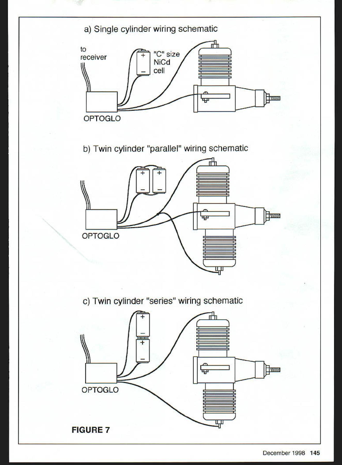
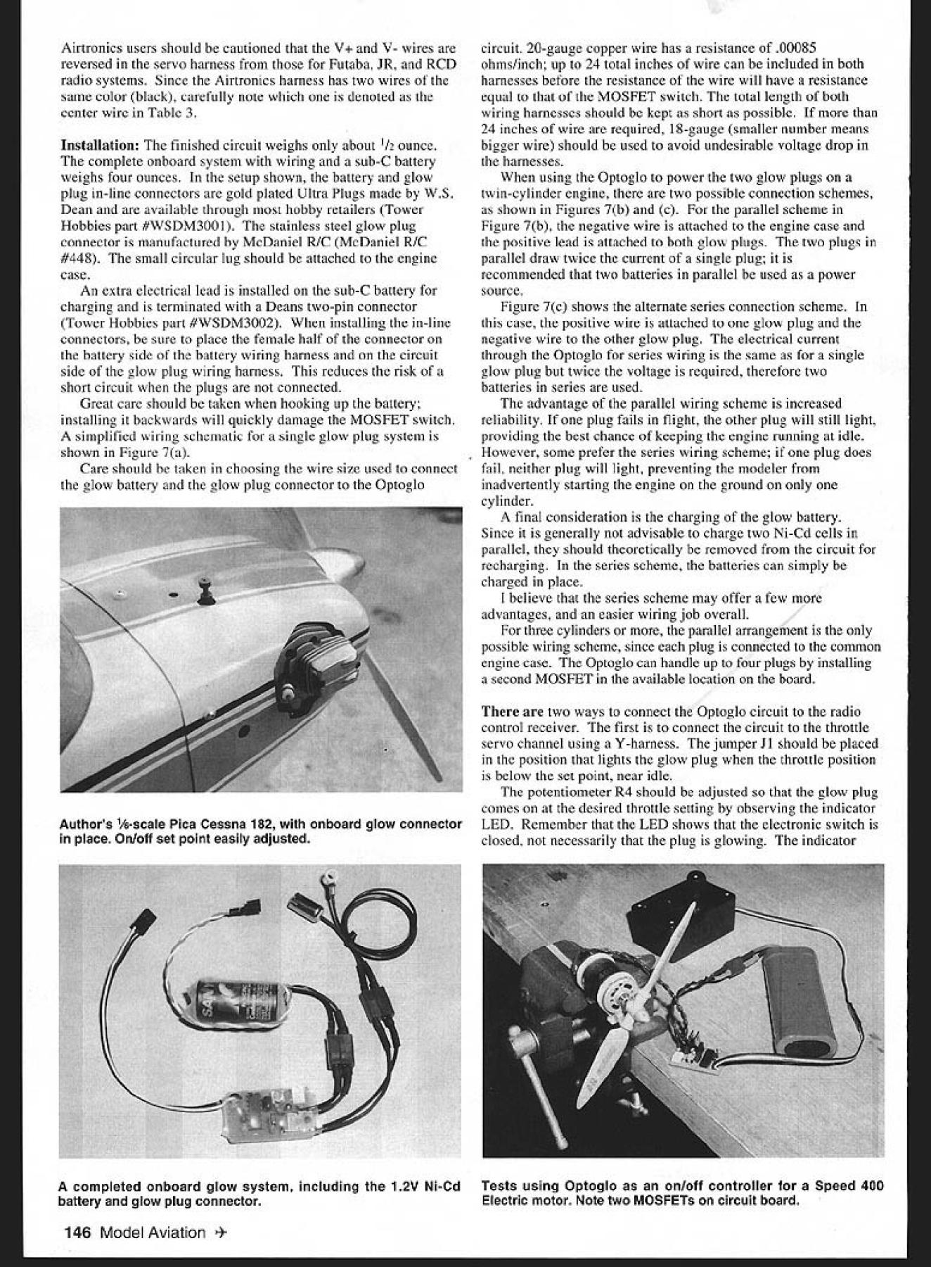
U Brent Dane ONBOARD GLOW system can add safety convenience model engine cases glow current required idle electronic glow system can connected unused radio channel allowing glow current switched off just flip switch transmitter Optoglo general-purpose electronic switch radio control airplane boat car applications primarily intended operate onboard glow systems model engines operating voltage up 50V high current switching capacity can used on/off control wide variety devices such smoke pumps lighting systems motors Electrics Complete optical isolation between receiver switch circuit eliminates possibility interference electrical noise Its straightforward design uses readily available electronic components common glow plug designed energized single Ni-Cd dry cell battery system consists rechargeable 1 2V Ni-Cd battery switch can remotely activated radio control system modeler never required disconnect glow power source running engine glow battery circuit can accomplished optical isolation switch used design referred logic level MOSFET necessary apply 5V MOSFET gate pin order activate switch compared typical iSV requirement Clearly 5V still voltage 12V available single cell glow plug side circuit reason special optical isolator used called photovoltaic isolator isolator small package size 8-pin integrated circuit 4 pins contains internal light-emitting diode LED photovoltaic array commonly referred solar cell array Current supplied LED generates light collected solar cells converted voltage Finishedon other side optoglo electronic switch Optical isolation elimisolator generated possibilitY interference electrical noisevoltage 5Vjust what necessary drive MOSFET gate communication between half Optoglo circuit connected radio receiver half connected glow plug circuit through photons light Remember signal receiver sent control servo train pulses ranging about 1 2 milliseconds duration occurring about 60 per second pulse width ims sends servo output limit rotation direction 2ms limit other example pulse width supplied servo near center position As began design Optoglo surprised find out average current draw typical glow plug about 3 amps 1 volt means filament resistance about 3 ohm reason special care must taken design electronic switch adds very little resistance glow plug circuit switch resistance comparable glow plug significant amount battery power will dissipated switch itself robs power plug also results heating electronic switch design have chosen MOSFET transistor resistance 02 ohm results less 10% power being dissipated transistor quite acceptable first glow switch design did incorporate optical isolation abandoned first design rough prototype stage An ideal solution absolutely no electrical connection between receiver electronics approximately 15 ins three wires connecting servo receiver first two supply plus minus voltage battery pack often red black respectively see Table 3 third wire carries pulses direct motion servo Optoglo has its own onboard adjustable reference pulse generator input pulses receiver longer onboard reference pulses electronic switch closes turns input pulses shorter switch opens turns off jumper Optoglo allows direction operation reversed open long pulses 142 Model Aviation * Graphic Design Jill Ann Cavanaugh closed short pulses jumper therefore functions way similar servo reversing switch Figure 2 shows electronic schematic Optoglo set point on/off changed adjusting potentiometer R4 R4 capacitor C2 determine reference pulse duration outputs pin 5 pin 12 _________ integrated circuit IC i have reversed polarity Moving jumper J2 applies _____ output either pin 5 pin 12 optical isolator IC2 Notice link between power switch side circuit side connected receiver through optical isolator red LED Dl lights indicate voltage being applied optical isolator closing high power MOSFET switch Ql D2 catch diode placed across device being powered Optoglo switch inductive loads such relay motor windings de energized produce voltage spike can cause erratic shut off characteristics catch diode suppresses possible spike Note schematic illustrates connections glow plug glow battery glow battery can replaced DC voltage source up 50V glow plug can wide range electrically powered devices CONSTRUCTION Table 1 complete parts list Optoglo catalog part numbers Digi-Key Electronics Figure 3 2X scaled pattern printed circuit board best way make board product called Press-n-Peel 2a blue plastic film can run through conventional photocopy machine printed onto directly laser printer Following instructions supplied film image Figure 3 should copied onto dull side ironed onto copper clad board such Radio Shack 276-1499 experimenting best temperature find useful securely tape film board along edge can carefully peel back small portion test adhesion pattern board transfer incomplete film let C B ng codes Table 3 0 input receiver ceiver battery R2 4 ---I215 314 413 512 611 7 10 Cl 8 9 R3 Cl R1 set point adjustment j/R4 ~2reversing 7indicator glow plug other device FIGURE 2 # parts Description Table 1 Digi-Key part number 1W resistor 220Q220QBK-ND 1W resistor 1k10KQBK-ND 2W resistor 47k47KQBK-ND 2W resistor lM1 0MQB K-ND 1100k rotary potentiometerD4AA 15-ND 1 2logic level power MOSFETIRLZ44N-ND 1polyester film capacitor 00561tFP4590-ND 1polyester film capacitor 0lgFP4593-ND 1red LED diffuse lensP363-ND 1600V silicon diode1N4005CT-ND 1dual retriggerable monostablemultivibrator MM74HC123AN-ND 15V photovoltaic isolatorPV15050-ND 13 pin square headerS 1011-03-ND 1shorting jumperS9002-ND December 1998 143 0 0 0 -I 0 FIGURE 3 electronic components required build Optoglo parts Digi-Key Table 1 shows complete list ] Receiver wiring harness see Table 3 color codes VB V 4 k 4 Optional second MOSFET~ 02 bend Glow battery Glow plug lea / dsy Optional horizontal mountingstriped end configuration single MOSFET JxdownforD2 side view FIGURE 5 Table 2 yellow purple orange* yellow purple orange brown black green rotary trim potentiometer 104 red red brown brown black red brown black green Transistors Qi IRLZ44 Logic level power MOSFET Q2 IRLZ44 Optional MOSFET Capacitors Cl0056gF C20lgF*** Diodes Dl redLED D21N4005 Integrated circuits ICL CD74123E 1C2 PV15050 * The last resistor color band gold 5% resistors ** 0056gF capacitor labeled 563 0lgF capacitor labeled 104 back down additional pressure used higher temperature After successful image transfer board etched solution ferric chloride Radio Shack 276-1535 30-60 minutes until unwanted copper gone particular blank board two-sided copper will completely removed back side After etching mounting holes should drilled #65 drill bit copper surrounding hole location accurately guides drilling Slightly larger holes will required MOSFET pins glow plug battery wires smallest possible holes should drilled case Figure 4 photograph complete set electronic components Figure 5 shows schematic installation components onto board should inserted side opposite copper circuit pattern resistors should mounted vertically Jumper J2 simply made leftover piece resistor lead Pay special attention Id 1C2 Dl D2 Ql well optional Q2 since direction installed very important Notice LED Dl has small flat spot should oriented shown figure indicator LED can also placed extension wires locate easily visible location airplane such cockpit area Diode D2 should installed striped end facing down Notice MOSFET QI can installed standing up its base flush circuit board leads can bent allowing folded over horizontally reducing overall height Optoglo latter case illustrated Figure 1 tab MOSFET may contact top lead D2 problem since transistor tab diode lead same voltage high current applications optional MOSFET Q2 can installed second board position both transistors standing position Carefully solder installed components copper circuit pattern taking care avoid solder bridges across gaps between traces extremely important use good quality resin-core electronics-grade solder brighten copper traces fine steel wool Scotch-Brite pad before starting excess resin left soldering should removed solvent such lacquer thinner epoxy brush bristles cut back receiver lead compatible radio system can purchased local hobby shop could use wiring harness worn out damaged servo Table 3 summarizes wire color codes typically used some common radio systems Using Figure 5 carefully attach leads according chart 144 Model Aviation al C Resistors Ri47k R247k R3iM R4100k R5220 R61k R7iM Table 3 ManufacturerNegative voltage APositive voltage BSignal C Airtronics/Sanwablack center wireblack red stripeblack Futabablackred center wirewhite Hitec/RCDblackred center wireyellow JRbrownred center wireorange KO Propoblackred center wireblue Kyosho/ulsarblackred center wireyellow Tower Hobbiesblackred center wirewhite NO OCR TEXT Airtronics users should cautioned V V- wires reversed servo harness Futaba JR RCD radio systems Since Airtronics harness has two wires same color black carefully note denoted center wire Table 3 Installation The finished circuit weighs about /2 ounce complete onboard system wiring sub-C battery weighs four ounces setup shown battery glow plug in-line connectors gold plated Ultra Plugs made WS Dean available through hobby retailers Tower Hobbies part #WSDM300 1 stainless steel glow plug connector manufactured McDaniel RIC McDaniel R/C #448 small circular lug should attached engine case An extra electrical lead installed sub-C battery charging terminated Deans two-pin connector Tower Hobbies part #WSDM3002 installing in-line connectors sure place female half connector battery side battery wiring harness circuit side glow plug wiring harness reduces risk short circuit plugs connected Great care should taken hooking up battery installing backwards will quickly damage MOSFET switch simplified wiring schematic single glow plug system shown Figure 7a Care should taken choosing wire size used connect glow battery glow plug connector Optoglo completed onboard glow system including 12V Ni-Cd battery glow plug connector circuit 20-gauge copper wire has resistance 00085 ohms/inch up 24 total inches wire can included both harnesses before resistance wire will have resistance equal MOSFET switch total length both wiring harnesses should kept short possible 24 inches wire required 18-gauge smaller number means bigger wire should used avoid undesirable voltage drop harnesses using Optoglo power two glow plugs twin-cylinder engine two possible connection schemes shown Figures 7b c parallel scheme Figure 7b negative wire attached engine case positive lead attached both glow plugs two plugs parallel draw twice current single plug recommended two batteries parallel used power source Figure 7c shows alternate series connection scheme case positive wire attached glow plug negative wire other glow plug electrical current through Optoglo series wiring same single glow plug twice voltage required therefore two batteries series used advantage parallel wiring scheme increased reliability plug fails flight other plug will still light providing best chance keeping engine running idle However some prefer series wiring scheme plug does fail neither plug will light preventing modeler inadvertently starting engine ground cylinder final consideration charging glow battery Since generally advisable charge two Ni-Cd cells parallel should theoretically removed circuit recharging series scheme batteries can simply charged place believe series scheme may offer few advantages easier wiring job overall three cylinders parallel arrangement possible wiring scheme since plug connected common engine case Optoglo can handle up four plugs installing second MOSFET available location board two ways connect Optoglo circuit radio control receiver first connect circuit throttle servo channel using Y-harness jumper Ji should placed position lights glow plug throttle position below set point near idle potentiometer R4 should adjusted glow plug comes desired throttle setting observing indicator LED Remember LED shows electronic switch closed necessarily plug glowing indicator Tests using Optoglo onloff controller Speed 400 Electric motor Note two MOSFETs circuit board 146 Model Aviation ors 1/e-scale Pica Cessna 182 onboard glow connector place Onlofl set point easily adjusted will light whether glow battery properly charged plug burned out second hookup option connect Optoglo separate receiver channel Electronic mixing receiver can used slave channel throttle servo channel preferred setup computer radio mixing can deactivated desired glow power can applied needed flip switch glow channel Sliding finished circuit short length 1 25-inch-diameter heat-shrink tubing provides protection circuit careful overheat circuit shrinking set access holes can cut through covering allow set point adjustments move reversing jumper circuit connected separate receiver channel described earlier access adjustments may necessary since can accomplished receiver programming like wrap finished circuit layer x foam held couple rubber bands shield against engine vibration Optoglo can used on/off switch variety devices operating battery voltages up SOy Optoglo can easily handle 5-6 amps current single MOSFET transistor installed no heatsinking required current handling can doubled adding additional optional MOSFET aggressive cooling added attaching finned aluminum heat sinks MOSFET devices rated continuous current up 40 amps Optoglo can also used small inexpensive switch increasingly popular Speed 400 similar Electric motors controlling Electric motor very important reversing jumper always placed position nearest edge circuit board motor doesnt start transmitter turned off before receiver t Dane 678 Crane Ave Livermore CA 94550 Sources Digi-Key Corporation 701 Brooks Ave South Thief River Falls MN 56701-0677 Tel 800 344-4539 Press-n-Peel manufactured Techniks can ordered Electronics Corp VanNuys CA 91411 Tel 818 997-1806 Etched printed circuit board Available author send check money order $10 per board complete unassembled kit wiring harnesses battery can obtained $25 includes postage handling Add additional $5 second MOSFET transistor applications requiring six amps current December 1998 147 NEW LASER PLAN PACS Dont pay big bucks wwl kits top quality plans laser cut parts available 1/4 Scale0rt 84 Span Plans $2500 FG Cowl $2500 Laser cut parts $6500 1/5th Scale Plans $35 00 Laser Cut parts $7500 Plans $25 00 Laser Cut partS $7500 t/4 scale ALBATROS OVA Plans $3600 Laser parts $7500 1/6th Scale pan PLANS $2600 Laser cut parts $6500 1/4 Scale Maey mareSESA PLANS $3500 Laser Pacs availableLaser parts $15000 SHIPPING AD $500 TO PLANS ORDER $800 TO LASER PAC BEST IN SCALE CATALOG $700 POST PAID BOB HOLMAN PLANS PO BOX 741 SAM BERNARDINO CA 92402 909 885 3959 FAX 909 889 9307 Kestrel 2M has introduction larger yen Kestrel lIju wiin arger greater performance ta increase wings speed r wingloading planform ate breakthrough sailplane NSP w s I c o in

Edition: Model Aviation - 1998/12
Page Numbers: 142, 143, 144, 145, 146, 147
U Brent Dane ONBOARD GLOW system can add safety convenience model engine cases glow current required idle electronic glow system can connected unused radio channel allowing glow current switched off just flip switch transmitter Optoglo general-purpose electronic switch radio control airplane boat car applications primarily intended operate onboard glow systems model engines operating voltage up 50V high current switching capacity can used on/off control wide variety devices such smoke pumps lighting systems motors Electrics Complete optical isolation between receiver switch circuit eliminates possibility interference electrical noise Its straightforward design uses readily available electronic components common glow plug designed energized single Ni-Cd dry cell battery system consists rechargeable 1 2V Ni-Cd battery switch can remotely activated radio control system modeler never required disconnect glow power source running engine glow battery circuit can accomplished optical isolation switch used design referred logic level MOSFET necessary apply 5V MOSFET gate pin order activate switch compared typical iSV requirement Clearly 5V still voltage 12V available single cell glow plug side circuit reason special optical isolator used called photovoltaic isolator isolator small package size 8-pin integrated circuit 4 pins contains internal light-emitting diode LED photovoltaic array commonly referred solar cell array Current supplied LED generates light collected solar cells converted voltage Finishedon other side optoglo electronic switch Optical isolation elimisolator generated possibilitY interference electrical noisevoltage 5Vjust what necessary drive MOSFET gate communication between half Optoglo circuit connected radio receiver half connected glow plug circuit through photons light Remember signal receiver sent control servo train pulses ranging about 1 2 milliseconds duration occurring about 60 per second pulse width ims sends servo output limit rotation direction 2ms limit other example pulse width supplied servo near center position As began design Optoglo surprised find out average current draw typical glow plug about 3 amps 1 volt means filament resistance about 3 ohm reason special care must taken design electronic switch adds very little resistance glow plug circuit switch resistance comparable glow plug significant amount battery power will dissipated switch itself robs power plug also results heating electronic switch design have chosen MOSFET transistor resistance 02 ohm results less 10% power being dissipated transistor quite acceptable first glow switch design did incorporate optical isolation abandoned first design rough prototype stage An ideal solution absolutely no electrical connection between receiver electronics approximately 15 ins three wires connecting servo receiver first two supply plus minus voltage battery pack often red black respectively see Table 3 third wire carries pulses direct motion servo Optoglo has its own onboard adjustable reference pulse generator input pulses receiver longer onboard reference pulses electronic switch closes turns input pulses shorter switch opens turns off jumper Optoglo allows direction operation reversed open long pulses 142 Model Aviation * Graphic Design Jill Ann Cavanaugh closed short pulses jumper therefore functions way similar servo reversing switch Figure 2 shows electronic schematic Optoglo set point on/off changed adjusting potentiometer R4 R4 capacitor C2 determine reference pulse duration outputs pin 5 pin 12 _________ integrated circuit IC i have reversed polarity Moving jumper J2 applies _____ output either pin 5 pin 12 optical isolator IC2 Notice link between power switch side circuit side connected receiver through optical isolator red LED Dl lights indicate voltage being applied optical isolator closing high power MOSFET switch Ql D2 catch diode placed across device being powered Optoglo switch inductive loads such relay motor windings de energized produce voltage spike can cause erratic shut off characteristics catch diode suppresses possible spike Note schematic illustrates connections glow plug glow battery glow battery can replaced DC voltage source up 50V glow plug can wide range electrically powered devices CONSTRUCTION Table 1 complete parts list Optoglo catalog part numbers Digi-Key Electronics Figure 3 2X scaled pattern printed circuit board best way make board product called Press-n-Peel 2a blue plastic film can run through conventional photocopy machine printed onto directly laser printer Following instructions supplied film image Figure 3 should copied onto dull side ironed onto copper clad board such Radio Shack 276-1499 experimenting best temperature find useful securely tape film board along edge can carefully peel back small portion test adhesion pattern board transfer incomplete film let C B ng codes Table 3 0 input receiver ceiver battery R2 4 ---I215 314 413 512 611 7 10 Cl 8 9 R3 Cl R1 set point adjustment j/R4 ~2reversing 7indicator glow plug other device FIGURE 2 # parts Description Table 1 Digi-Key part number 1W resistor 220Q220QBK-ND 1W resistor 1k10KQBK-ND 2W resistor 47k47KQBK-ND 2W resistor lM1 0MQB K-ND 1100k rotary potentiometerD4AA 15-ND 1 2logic level power MOSFETIRLZ44N-ND 1polyester film capacitor 00561tFP4590-ND 1polyester film capacitor 0lgFP4593-ND 1red LED diffuse lensP363-ND 1600V silicon diode1N4005CT-ND 1dual retriggerable monostablemultivibrator MM74HC123AN-ND 15V photovoltaic isolatorPV15050-ND 13 pin square headerS 1011-03-ND 1shorting jumperS9002-ND December 1998 143 0 0 0 -I 0 FIGURE 3 electronic components required build Optoglo parts Digi-Key Table 1 shows complete list ] Receiver wiring harness see Table 3 color codes VB V 4 k 4 Optional second MOSFET~ 02 bend Glow battery Glow plug lea / dsy Optional horizontal mountingstriped end configuration single MOSFET JxdownforD2 side view FIGURE 5 Table 2 yellow purple orange* yellow purple orange brown black green rotary trim potentiometer 104 red red brown brown black red brown black green Transistors Qi IRLZ44 Logic level power MOSFET Q2 IRLZ44 Optional MOSFET Capacitors Cl0056gF C20lgF*** Diodes Dl redLED D21N4005 Integrated circuits ICL CD74123E 1C2 PV15050 * The last resistor color band gold 5% resistors ** 0056gF capacitor labeled 563 0lgF capacitor labeled 104 back down additional pressure used higher temperature After successful image transfer board etched solution ferric chloride Radio Shack 276-1535 30-60 minutes until unwanted copper gone particular blank board two-sided copper will completely removed back side After etching mounting holes should drilled #65 drill bit copper surrounding hole location accurately guides drilling Slightly larger holes will required MOSFET pins glow plug battery wires smallest possible holes should drilled case Figure 4 photograph complete set electronic components Figure 5 shows schematic installation components onto board should inserted side opposite copper circuit pattern resistors should mounted vertically Jumper J2 simply made leftover piece resistor lead Pay special attention Id 1C2 Dl D2 Ql well optional Q2 since direction installed very important Notice LED Dl has small flat spot should oriented shown figure indicator LED can also placed extension wires locate easily visible location airplane such cockpit area Diode D2 should installed striped end facing down Notice MOSFET QI can installed standing up its base flush circuit board leads can bent allowing folded over horizontally reducing overall height Optoglo latter case illustrated Figure 1 tab MOSFET may contact top lead D2 problem since transistor tab diode lead same voltage high current applications optional MOSFET Q2 can installed second board position both transistors standing position Carefully solder installed components copper circuit pattern taking care avoid solder bridges across gaps between traces extremely important use good quality resin-core electronics-grade solder brighten copper traces fine steel wool Scotch-Brite pad before starting excess resin left soldering should removed solvent such lacquer thinner epoxy brush bristles cut back receiver lead compatible radio system can purchased local hobby shop could use wiring harness worn out damaged servo Table 3 summarizes wire color codes typically used some common radio systems Using Figure 5 carefully attach leads according chart 144 Model Aviation al C Resistors Ri47k R247k R3iM R4100k R5220 R61k R7iM Table 3 ManufacturerNegative voltage APositive voltage BSignal C Airtronics/Sanwablack center wireblack red stripeblack Futabablackred center wirewhite Hitec/RCDblackred center wireyellow JRbrownred center wireorange KO Propoblackred center wireblue Kyosho/ulsarblackred center wireyellow Tower Hobbiesblackred center wirewhite NO OCR TEXT Airtronics users should cautioned V V- wires reversed servo harness Futaba JR RCD radio systems Since Airtronics harness has two wires same color black carefully note denoted center wire Table 3 Installation The finished circuit weighs about /2 ounce complete onboard system wiring sub-C battery weighs four ounces setup shown battery glow plug in-line connectors gold plated Ultra Plugs made WS Dean available through hobby retailers Tower Hobbies part #WSDM300 1 stainless steel glow plug connector manufactured McDaniel RIC McDaniel R/C #448 small circular lug should attached engine case An extra electrical lead installed sub-C battery charging terminated Deans two-pin connector Tower Hobbies part #WSDM3002 installing in-line connectors sure place female half connector battery side battery wiring harness circuit side glow plug wiring harness reduces risk short circuit plugs connected Great care should taken hooking up battery installing backwards will quickly damage MOSFET switch simplified wiring schematic single glow plug system shown Figure 7a Care should taken choosing wire size used connect glow battery glow plug connector Optoglo completed onboard glow system including 12V Ni-Cd battery glow plug connector circuit 20-gauge copper wire has resistance 00085 ohms/inch up 24 total inches wire can included both harnesses before resistance wire will have resistance equal MOSFET switch total length both wiring harnesses should kept short possible 24 inches wire required 18-gauge smaller number means bigger wire should used avoid undesirable voltage drop harnesses using Optoglo power two glow plugs twin-cylinder engine two possible connection schemes shown Figures 7b c parallel scheme Figure 7b negative wire attached engine case positive lead attached both glow plugs two plugs parallel draw twice current single plug recommended two batteries parallel used power source Figure 7c shows alternate series connection scheme case positive wire attached glow plug negative wire other glow plug electrical current through Optoglo series wiring same single glow plug twice voltage required therefore two batteries series used advantage parallel wiring scheme increased reliability plug fails flight other plug will still light providing best chance keeping engine running idle However some prefer series wiring scheme plug does fail neither plug will light preventing modeler inadvertently starting engine ground cylinder final consideration charging glow battery Since generally advisable charge two Ni-Cd cells parallel should theoretically removed circuit recharging series scheme batteries can simply charged place believe series scheme may offer few advantages easier wiring job overall three cylinders parallel arrangement possible wiring scheme since plug connected common engine case Optoglo can handle up four plugs installing second MOSFET available location board two ways connect Optoglo circuit radio control receiver first connect circuit throttle servo channel using Y-harness jumper Ji should placed position lights glow plug throttle position below set point near idle potentiometer R4 should adjusted glow plug comes desired throttle setting observing indicator LED Remember LED shows electronic switch closed necessarily plug glowing indicator Tests using Optoglo onloff controller Speed 400 Electric motor Note two MOSFETs circuit board 146 Model Aviation ors 1/e-scale Pica Cessna 182 onboard glow connector place Onlofl set point easily adjusted will light whether glow battery properly charged plug burned out second hookup option connect Optoglo separate receiver channel Electronic mixing receiver can used slave channel throttle servo channel preferred setup computer radio mixing can deactivated desired glow power can applied needed flip switch glow channel Sliding finished circuit short length 1 25-inch-diameter heat-shrink tubing provides protection circuit careful overheat circuit shrinking set access holes can cut through covering allow set point adjustments move reversing jumper circuit connected separate receiver channel described earlier access adjustments may necessary since can accomplished receiver programming like wrap finished circuit layer x foam held couple rubber bands shield against engine vibration Optoglo can used on/off switch variety devices operating battery voltages up SOy Optoglo can easily handle 5-6 amps current single MOSFET transistor installed no heatsinking required current handling can doubled adding additional optional MOSFET aggressive cooling added attaching finned aluminum heat sinks MOSFET devices rated continuous current up 40 amps Optoglo can also used small inexpensive switch increasingly popular Speed 400 similar Electric motors controlling Electric motor very important reversing jumper always placed position nearest edge circuit board motor doesnt start transmitter turned off before receiver t Dane 678 Crane Ave Livermore CA 94550 Sources Digi-Key Corporation 701 Brooks Ave South Thief River Falls MN 56701-0677 Tel 800 344-4539 Press-n-Peel manufactured Techniks can ordered Electronics Corp VanNuys CA 91411 Tel 818 997-1806 Etched printed circuit board Available author send check money order $10 per board complete unassembled kit wiring harnesses battery can obtained $25 includes postage handling Add additional $5 second MOSFET transistor applications requiring six amps current December 1998 147 NEW LASER PLAN PACS Dont pay big bucks wwl kits top quality plans laser cut parts available 1/4 Scale0rt 84 Span Plans $2500 FG Cowl $2500 Laser cut parts $6500 1/5th Scale Plans $35 00 Laser Cut parts $7500 Plans $25 00 Laser Cut partS $7500 t/4 scale ALBATROS OVA Plans $3600 Laser parts $7500 1/6th Scale pan PLANS $2600 Laser cut parts $6500 1/4 Scale Maey mareSESA PLANS $3500 Laser Pacs availableLaser parts $15000 SHIPPING AD $500 TO PLANS ORDER $800 TO LASER PAC BEST IN SCALE CATALOG $700 POST PAID BOB HOLMAN PLANS PO BOX 741 SAM BERNARDINO CA 92402 909 885 3959 FAX 909 889 9307 Kestrel 2M has introduction larger yen Kestrel lIju wiin arger greater performance ta increase wings speed r wingloading planform ate breakthrough sailplane NSP w s I c o in

