
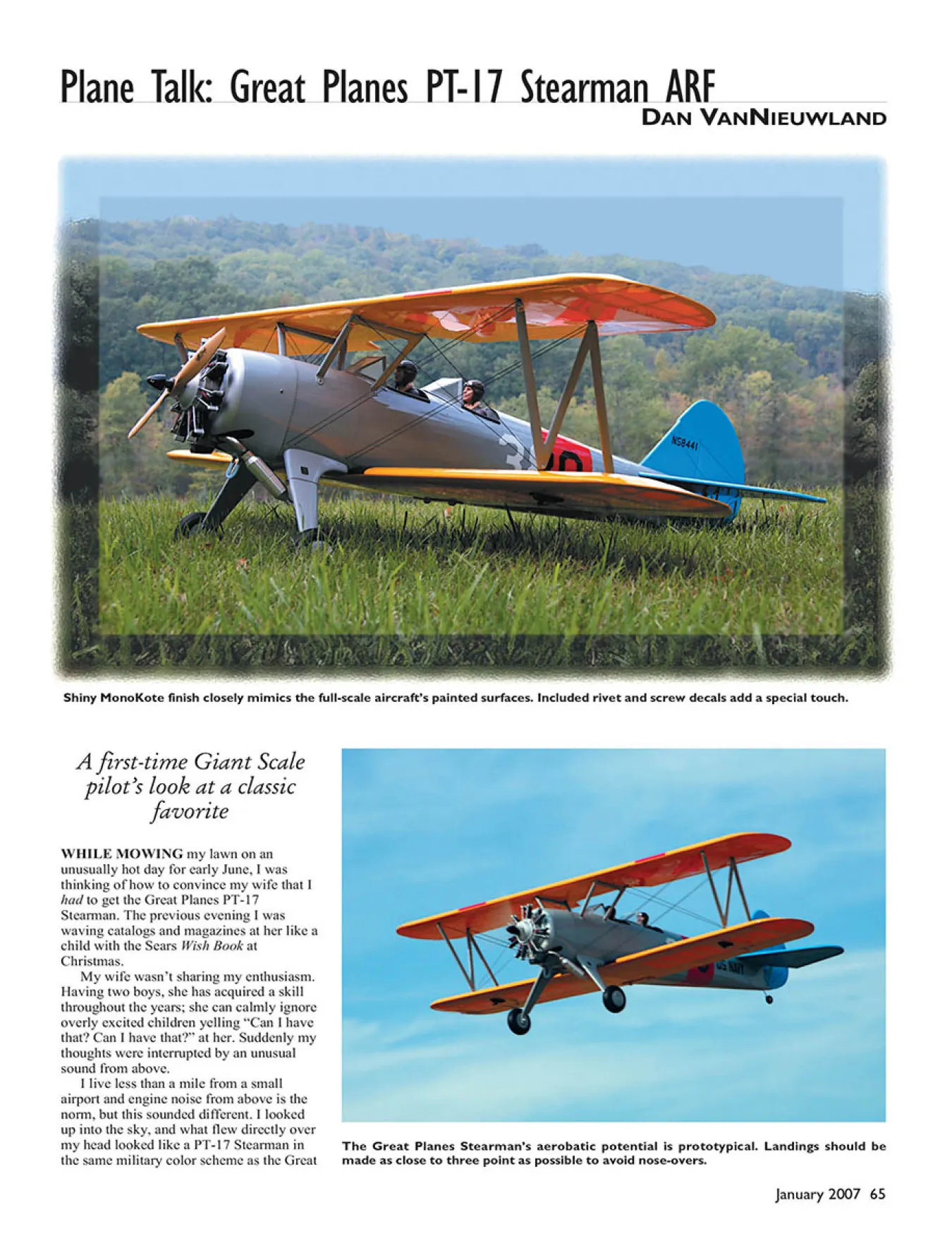
Shiny MonoKote finish closely mimics the full-scale aircraft’s painted surfaces. Included rivet and screw decals add a special touch.
WHILE MOWING my lawn on an
unusually hot day for early June, I was
thinking of how to convince my wife that I
had to get the Great Planes PT-17
Stearman. The previous evening I was
waving catalogs and magazines at her like a
child with the Sears Wish Book at
Christmas.
My wife wasn’t sharing my enthusiasm.
Having two boys, she has acquired a skill
throughout the years; she can calmly ignore
overly excited children yelling “Can I have
that? Can I have that?” at her. Suddenly my
thoughts were interrupted by an unusual
sound from above.
I live less than a mile from a small
airport and engine noise from above is the
norm, but this sounded different. I looked
up into the sky, and what flew directly over
my head looked like a PT-17 Stearman in
the same military color scheme as the Great
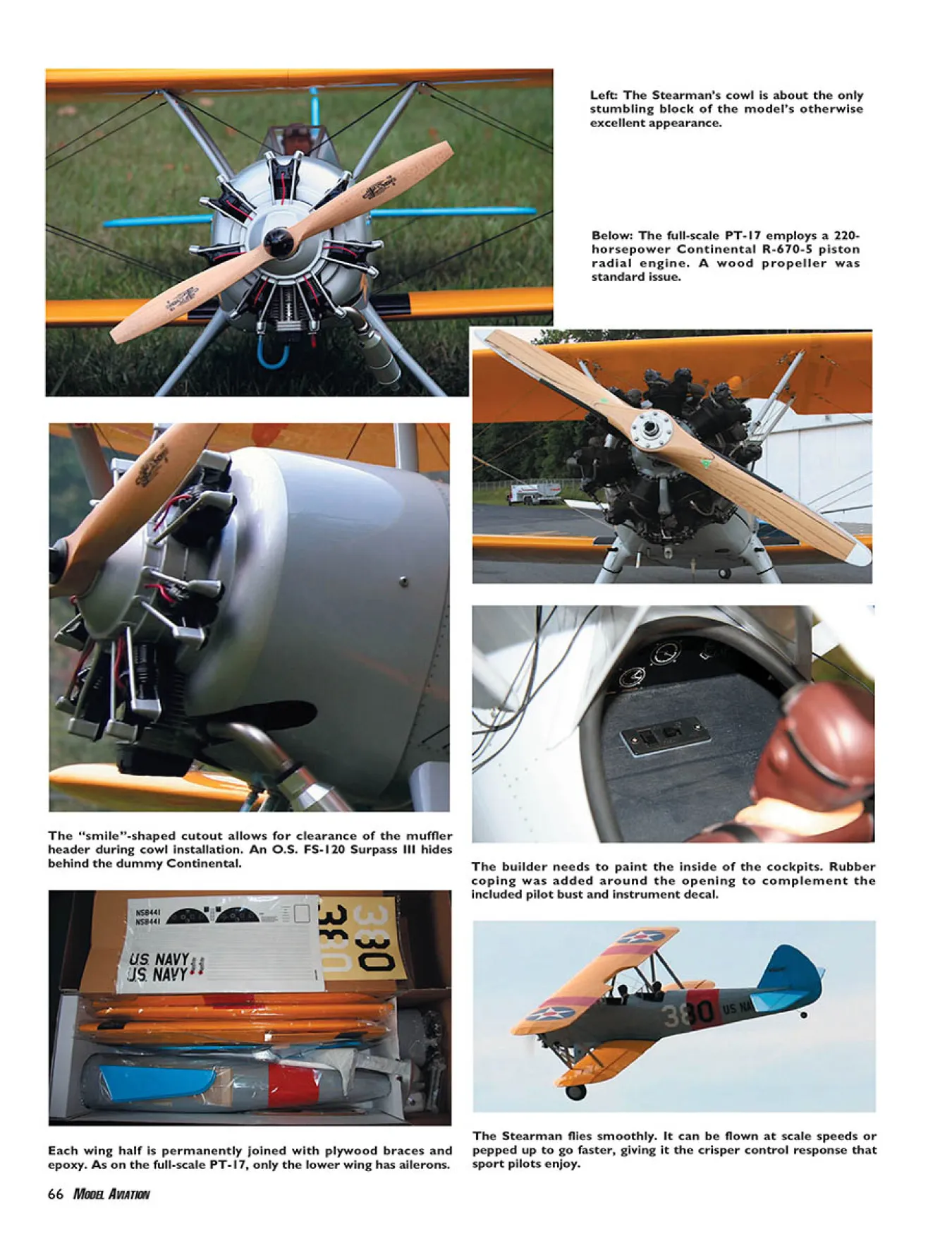
The Great Planes Stearman’s aerobatic potential is prototypical. Landings should be
made as close to three point as possible to avoid nose-overs.
66 MODEL AVIATION
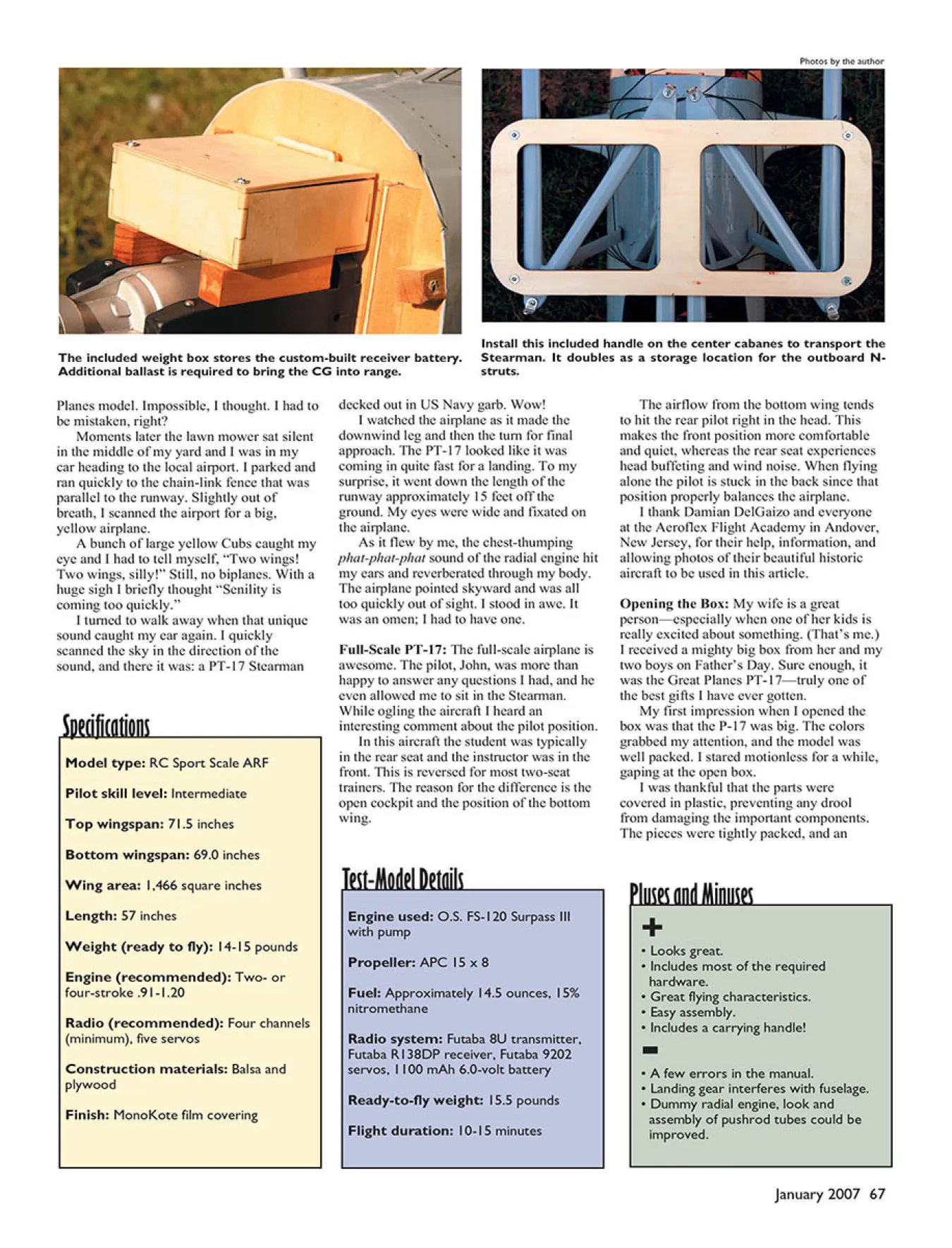
The Stearman flies smoothly. It can be flown at scale speeds or
pepped up to go faster, giving it the crisper control response that
sport pilots enjoy.
Each wing half is permanently joined with plywood braces and
epoxy. As on the full-scale PT-17, only the lower wing has ailerons.
Left: The Stearman’s cowl is about the only
stumbling block of the model’s otherwise
excellent appearance.
Below: The full-scale PT-17 employs a 220-
horsepower Continental R-670-5 piston
radial engine. A wood propeller was
standard issue.
The “smile”-shaped cutout allows for clearance of the muffler
header during cowl installation. An O.S. FS-120 Surpass III hides
behind the dummy Continental. The builder needs to paint the inside of the cockpits. Rubber
coping was added around the opening to complement the
included pilot bust and instrument decal.
January 2007 67
Model type: RC Sport Scale ARF
Pilot skill level: Intermediate
Top wingspan: 71.5 inches
Bottom wingspan: 69.0 inches
Wing area: 1,466 square inches
Length: 57 inches
Weight (ready to fly): 14-15 pounds
Engine (recommended): Two- or
four-stroke .91-1.20
Radio (recommended): Four channels
(minimum), five servos
Construction materials: Balsa and
plywood
Finish: MonoKote film covering
Specifications
Engine used: O.S. FS-120 Surpass III
with pump
Propeller: APC 15 x 8
Fuel: Approximately 14.5 ounces, 15%
nitromethane
Radio system: Futaba 8U transmitter,
Futaba R138DP receiver, Futaba 9202
servos, 1100 mAh 6.0-volt battery
Ready-to-fly weight: 15.5 pounds
Flight duration: 10-15 minutes
Test-Model Details
+
• Looks great.
• Includes most of the required
hardware.
• Great flying characteristics.
• Easy assembly.
• Includes a carrying handle! -• A few errors in the manual.
• Landing gear interferes with fuselage.
• Dummy radial engine, look and
assembly of pushrod tubes could be
improved.
Pluses and Minuses
The included weight box stores the custom-built receiver battery.
Additional ballast is required to bring the CG into range.
Install this included handle on the center cabanes to transport the
Stearman. It doubles as a storage location for the outboard Nstruts.
Planes model. Impossible, I thought. I had to
be mistaken, right?
Moments later the lawn mower sat silent
in the middle of my yard and I was in my
car heading to the local airport. I parked and
ran quickly to the chain-link fence that was
parallel to the runway. Slightly out of
breath, I scanned the airport for a big,
yellow airplane.
A bunch of large yellow Cubs caught my
eye and I had to tell myself, “Two wings!
Two wings, silly!” Still, no biplanes. With a
huge sigh I briefly thought “Senility is
coming too quickly.”
I turned to walk away when that unique
sound caught my ear again. I quickly
scanned the sky in the direction of the
sound, and there it was: a PT-17 Stearman
decked out in US Navy garb. Wow!
I watched the airplane as it made the
downwind leg and then the turn for final
approach. The PT-17 looked like it was
coming in quite fast for a landing. To my
surprise, it went down the length of the
runway approximately 15 feet off the
ground. My eyes were wide and fixated on
the airplane.
As it flew by me, the chest-thumping
phat-phat-phat sound of the radial engine hit
my ears and reverberated through my body.
The airplane pointed skyward and was all
too quickly out of sight. I stood in awe. It
was an omen; I had to have one.
Full-Scale PT-17: The full-scale airplane is
awesome. The pilot, John, was more than
happy to answer any questions I had, and he
even allowed me to sit in the Stearman.
While ogling the aircraft I heard an
interesting comment about the pilot position.
In this aircraft the student was typically
in the rear seat and the instructor was in the
front. This is reversed for most two-seat
trainers. The reason for the difference is the
open cockpit and the position of the bottom
wing.
The airflow from the bottom wing tends
to hit the rear pilot right in the head. This
makes the front position more comfortable
and quiet, whereas the rear seat experiences
head buffeting and wind noise. When flying
alone the pilot is stuck in the back since that
position properly balances the airplane.
I thank Damian DelGaizo and everyone
at the Aeroflex Flight Academy in Andover,
New Jersey, for their help, information, and
allowing photos of their beautiful historic
aircraft to be used in this article.
Opening the Box: My wife is a great
person—especially when one of her kids is
really excited about something. (That’s me.)
I received a mighty big box from her and my
two boys on Father’s Day. Sure enough, it
was the Great Planes PT-17—truly one of
the best gifts I have ever gotten.
My first impression when I opened the
box was that the P-17 was big. The colors
grabbed my attention, and the model was
well packed. I stared motionless for a while,
gaping at the open box.
I was thankful that the parts were
covered in plastic, preventing any drool
from damaging the important components.
The pieces were tightly packed, and an
Photos by the author
appropriate level of packing material
appeared to have been used.
I found no dings or damaged parts. One
thing I noticed during the inspection was
that the MonoKote covering was wrinkled
on all the components. An iron and a heat
gun did a good job of removing most of the
creases.
The exception was around the ailerons,
and those wrinkles were minor. Not being a
covering expert, the job Great Planes did is
better than I could have done and is quite
good overall.
When I laid the pieces out on the floor,
the airplane looked enormous. This was my
first 1/4-scale airplane, and its size was a bit
intimidating.
My 9-year-old son pointed out that he
thought it was roughly the same size as my
aerobatic trainer: a Sig Four-Star 60. He
was right; other than the wideness of the
fuselage, the wingspan and fuselage length
were comparable. Thanks to my son, my
intimidation waned.
The Model: The Great Planes PT-17
Stearman was based on the existing Great
Planes Super Stearman, and there are some
noticeable differences between the two. The
Super Stearman has ailerons on the upper
and lower wing; the PT-17 has ailerons on
the bottom wing only. The engine is cowled
in on the Super Stearman, and it has wheel
pants. In addition, the color scheme is much
different.
Both models’ instruction booklets were
reviewed, and assembly appeared to be
similar. The PT-17’s manual was good, and
photos were included for almost every step.
The directions did contain a few errors,
including steps in which the text and photos
didn’t match. Apart from these minor
issues, the instructions were excellent.
The kit came with almost everything
needed to build the airplane other than the
typical building supplies and tools. Included
were the dummy pilots and radial engine,
wheel covers, scale decals (including
rivets), windscreens, and even precut balsa
fixture blocks to set the dihedral properly.
As I pointed out, the kit came with
“almost everything”; the rigging wire was
missing. As recommended by the
manufacturer, rigging wire is an elastic
thread called “beading cord,” or “beading
elastic,” that you can find in stores that sell
sewing supplies. The beading cord cost only
a few dollars (much less than the $10
indicated in the instructions) but was a bit
difficult to find.
The rigging wires add much more than
just “minor scale detail.” They add
character and realism for a low cost and
small time investment. Take the time and
pay the few dollars to add them; you will be
glad you did.
Doing the Last Thing First: After reading
through the instructions I decided to
perform one step out of sequence: painting
the cockpits. This was listed near the end of
the assembly process.
Personnel at the local hobby shop
informed me that the only supplier they
knew that sold “brushable” fuelproof flatblack
paint didn’t carry it anymore. Since
spray painting was the way to go, I decided
to paint the fuselage before attaching
additional parts to it. This was a good
decision overall.
I taped and covered the fuselage with
newspaper before I painted. I applied
several light coats of Flat Black LustreKote
to the bottom side of the top portion of the
cockpit (the part under the windshield)
before I painted the cockpit floor. It helps
eliminate runs and drips on the cockpit floor
if you paint the entire cockpit at one time.
Be careful handling the model around
the cockpit area. It seemed that was the
place to grab whenever the airplane was
moved. The balsa sheeting in that area had
no backing and could be easily damaged
because of the model’s weight.
Wing Assembly: Putting the wings together
was straightforward. The bottom wing has
some dihedral and the top wing is straight.
The wing halves were permanently secured
with plywood wing joiners and epoxy.
The photo and instructions for joining
the bottom wing halves did not match. The
text instructed the builder to place the
supplied block of wood under the wing half
flat on the workbench (one is in the air
because of the dihedral). The photo in the
instructions showed the block under the
wing in the air.
I decided to place the block under the
wing on the workbench since the
instructions were in bold print for this step
and the photo in the Super Stearman
instructions showed the block under the
wing on the workbench matching the text in
both manuals.
I secured the control surfaces using
cyanoacrylate hinges. The hinge slots were
precut and were wide enough to allow for
proper positioning. The hinges fit snugly
into the hinge slots, and only two slots
needed minor help with a hobby knife.
Owing to irregularities between the
ailerons and the wing, the control-surface
gap was larger than desired but acceptable.
You could seal the hinge gap with Cub
Yellow MonoKote if you wanted.
The bottom wing was secured to the
fuselage by two dowels that were glued into
predrilled holes on the LE and two nylon
wing bolts. The top wing was secured by
two pairs of cabanes (supports) in the
middle and at each end of the wing. The N
struts connecting the top and bottom wing
looked good and nicely replicated the fullscale
airplane.
The wing was secured to the cabanes by
eight 4-40 socket-head screws. If your luck
is like mine, if you drop one of these little
screws into the grass during assembly, you
won’t find it no matter how long you look.
Keep some spares in your field box.
When transporting the model, the outer
N struts are secured in a wooden cradle that
is attached to the center wing support. This
wooden cradle doubles as a carrying handle
for the Stearman. This feature is useful and
makes it much easier to carry the model
around.
Be careful not to run the engine while
the cabanes are in the holder. I did that, and
the finish on the cabanes was marred from
the engine vibration.
Mounting the Engine: Engine mounting
was easy, thanks to the supplied mount and
predrilled mounting holes in the firewall. I
installed an O.S. FS-120 Surpass III fourstroke,
which was on the high end of the
recommended range. The engine was
mounted inverted, which allowed the
exhaust to exit neatly from the bottom of the
cowl.
Another nicety of this model is that the
appropriate engine thrust and offset was
already built into it; no shimming of the
engine mount was necessary. So don’t
worry if the engine looks a bit crooked and
off center.
Engine Cowl and Dummy Radial Engine:
The radial engine is one thing that gives the
PT-17 its character. It also gives the model
its good looks and a nice level of detail,
including the pushrod tubes and the sparkplug
wires.
The supplied dummy radial engine
looked good; however, it did have a few
oddities.
The spacing between the cylinders on
the dummy engine was large when
compared to that on the full-scale airplane.
In addition, the rocker covers where the
pushrods attached were at an odd angle on
the dummy radial. When drilling the holes
for the pushrods, I had to make sure they
were made at an angle so they connected on
the opposite end.
The paint on the cowl looked good and
handled flexing well. The cowl was flexed
more than it probably should have been
during assembly, and the paint stayed on
securely with no cracking, flaking, or
chipping.
I encountered some difficulty getting the
cowl to fit over the engine header. While
fitting the cowl the smile-shaped cutout got
larger and larger. To add to the concern my
cowl had a much bigger smile than that
shown on the photos on the box. It was later
determined that the model in the photo had
a smaller engine, which was probably the
reason for the smaller smile.
In addition to the basic assembly, cutting
the cowl to make it fit just right and look
good took some patience. Okay, it took a lot
of patience. Take the time; work on it in
spurts if necessary. The result will be a
source of pride.
Weight Box and Battery Installation: The
kit included a weight box made from light
plywood that, once assembled, was attached
to the engine mount. The instructions
mentioned that weight would probably be
required in the nose since the model was
somewhat short coupled.
It’s safe to say weight will be required if
you use the recommended engines. The
prototype used for the instructions had an
O.S. .91 four-stroke and required 18 ounces
of weight. The instructions suggested
putting the battery in the weight box to
offset some of the lead weight.
I decided to use a 6-volt (five-cell)
receiver battery. This usually increases the
servos’ torque and speed. (Always check
the radio-equipment specifications.) Usually
a detriment to other models, the larger pack
adds slightly more weight, requiring less
lead ballast in the weight box.
I assembled, sanded, fuel-proofed, and
installed the weight box, and then a problem
emerged: it wasn’t large enough to hold a
five-cell pack. I disassembled the battery
pack and rearranged and soldered the cells
to fit into the box. The batteries fit, but they
were a bit snug once wrapped in foam.
Although the current arrangement should be
fine, I might install a larger box in the
future.
Even with the battery in the weight box
and using a 1.20-size engine instead of the
O.S. .91 prototype, 9 ounces of weight was
still required.
Landing Gear: The landing gear was a
solid piece of aluminum held up with 4-inch
wheels and matching wheel covers. The
strong landing gear was required to carry
the 14-15 pounds of weight, and it appears
capable of handling the occasional harsh
landing. The prepainted landing gear
blended beautifully with the rest of the PT-
17 and contributed to its character.
A minor problem I noticed was that the
landing gear interfered with the fuselage.
This caused a small wrinkle in the covering.
To correct the problem I added a lightplywood
spacer between the fuselage and
the landing gear. Once installed, the gap
between the fuselage and the gear is
unlikely to be noticed unless pointed out. It
looks like it should be that way anyway.
Receiver and Servo Installation: Installing
the servos and receiver was a breeze with
the luxuriously spacious, deep and wide
fuselage. Five servos were required: two
aileron, one rudder, one throttle, and one
elevator. The minimum recommended servo
specification was 54 ounce-inch of torque.
I chose the Futaba 9202 coreless servos,
which have 76 ounce-inch of torque at 4.8
volts and 98 ounce-inch of torque at 6.0
volts. I placed the receiver switch in the
front cockpit, where it is fairly
inconspicuous.
The model has a split elevator although
the pushrods are connected to one servo. An
elevator pushrod is attached to one elevator
half, and the other end is connected directly
to the servo. The second elevator pushrod is
connected to the other elevator half, and the
opposite end is attached to the first elevator
pushrod with two wheel collars.
The connection using the wheel collars
appears to be secure. I pulled, pushed, and
poked the control rods vigorously, and
observed no undesirable movement. For
added peace of mind I soldered the pushrods
together. It took only a few minutes and
created added insurance.
Decals: The full-scale PT-17 is a
combination of a metal panels and fabriccovered
sections. Metal panels are located
on top of the fuselage from the engine-cowl
ending to just behind the rear pilot seat.
The model’s decal kit included strips of
rivets to simulate the metal panels. The
rivets didn’t take long to add, and they are a
tasteful size. From a few yards away they
are difficult to even notice, but they look
great up close.
Two large circle-and-star decals were
included for placement on the top wing. The
full-scale airplane has these decals on the
underside of the bottom wing as well.
I considered purchasing another decal kit
to add the stars to the bottom wing, but that
would have made the bottom and top wing
look identical when inverted. I decided to
leave it alone and see how easy it would be
to recognize the model’s orientation.
Rigging Wires: I installed the wires by
drilling holes at points that were clearly
specified with photographs in the
instructions. To attach the rigging wires I
applied thin cyanoacrylate on the end of the
thread, making it stiff. Once dry I cut the
rigging wire at an angle to make a point.
The thread was easy to insert into the
holes, and I secured it with more
cyanoacrylate. If I ever need to replace the
wires, they can easily be cut, drilled, and
replaced.
The rigging wire for the rudder and
horizontal stabilizer are permanent and
require no assembly at the field. For the
wings, both sides of the rigging wires are
permanently secured (glued) into the
fuselage to make a loop. The opposite end is
wrapped around the outer N struts when the
PT-17 is assembled.
The photo on the box showed the rigging
wire attached to the front of the cabane on
one wing and on the rear of the cabane on
the opposite wing. As shown in photos of
the full-scale airplane, they should both go
to the front of the cabane.
Flying: Great Planes advertisements
describe the PT-17 as a great first biplane.
Since this is my first biplane and I consider
myself an intermediate pilot, I’m probably
an excellent target customer. I am also
comfortable flying and know basic
aerobatics.
I waited for a calm, sunny day for the
maiden flight. It took awhile to get here, but
when it arrived the air was filled with
excitement—not only mine, but that of a
small crowd of club members, my wife, and
my two children.
In addition to the normal knee knocking
of a first flight, this was also the first time I
was piloting the maiden flight. In the past
this honor was usually reserved for more
experienced club members, quite a few of
whom were standing beside me. It was
actually calming. Thanks, guys!
I taxied the PT-17 the length of the grass
runway a few times, occasionally adding
throttle to observe the response. I also used
this extra time to reduce my knee knocking.
When that was accomplished and my vision
was no longer blurred (kidding!), I lined the
model up on the runway centerline and
prepared for takeoff.
I slowly applied throttle and the airplane
started to rumble down the runway. Only
minor rudder corrections were necessary,
and I observed no unexpected behavior. The
tail wheel lifted off the ground, and shortly
thereafter the PT-17 was in the air at
approximately three-quarters throttle.
Only slight trim corrections were
necessary, and within a minute or two the
airplane was flying straight and level. After
trimming, my focus turned to flying. An
immediate reaction of “Wow!” melted all
my nervousness away.
The first flight was mainly a circuit
including ovals and figure eights. The PT-17
reacted as expected, with no bad behaviors,
and the flying was comfortable. The only
unexpected thing was that it flew slower
than predicted. I later learned that it was
because the model was a bit overpropped.
When some of my fellow club members
heard I had a biplane, a common comment
was “Biplanes fly until they don’t. Once
they stall, the stall is dramatic.” With plenty
of altitude I cut back the throttle to see when
the PT-17 would stall. It did so much later
than predicted. Once it happened, I quickly
regained control.
This experiment greatly reduced my
concerns about having the PT-17 stall. Club
members commented that it did so much
later than aerobatic biplanes they have
flown.
With the time to land approaching I
performed a few flybys to get into the
rhythm of lining up for landing. The slow
and low passes were beautiful. As good as
the PT-17 looked on the ground, it looked
even better in the air.
With my knees starting to quiver again, I
lined up the PT-17 for final. The landing
was uneventful other than being a bit fast. I
was still a little concerned about the PT-17
stalling at slow speed, and the idle was
purposely set slightly high to ensure that the
new engine would stay running. Otherwise,
the landing was perfect.
With my mind filled with confidence and
the PT-17 filled with fuel, I took it into the
air for a second flight. It performed beautiful
large loops, requiring only the slightest
rudder correction. Rolls were equally easy
and graceful, with the expected amount of
down-elevator required while the model was
inverted.
Keep in mind that the PT-17 is a scale
model—not an aerobatic biplane. It did not
perform some advanced maneuvers well. It
could execute knife-edge flight for only a
short distance, and then its nose would dive
and the model would roll out.
With the fuel running down and the sun
hanging low on the horizon, the PT-17’s
wheels touched the ground again. I cleaned
and disassembled the airplane and packed it
into the car to end a spectacular day.
In the following days I had the desire to
find out why the model flew slower than
expected. The engine’s manual did not
indicate its ideal rpm or show the torque
curve. I asked several club members for
their opinions (which are plentiful in our
club), and most of them said the maximum
rpm of 8,400 was too low.
I tried several propeller sizes and
manufacturers to get the highest rpm. The
winning combination was an APC 15 x 8
that reached a maximum of 9,100 rpm. I
confirmed with O.S. Engines’ tech
department that 9,100 rpm is correct and
that an increase should be observed once the
engine is broken in. At that point a larger
propeller may be used.
With a new propeller on its nose, I sent
the PT-17 into the air to see if there was a
difference. There was, and it was dramatic.
The model flew much faster and performed
better. The improvements pulled the
airplane’s speed into my realm of
expectations and made the flying experience
much more enjoyable.
That flight’s landing was a bit hard
because of pilot error, but it wasn’t too bad.
The PT-17 took one large hop before
settling onto the runway.
After the flight I noticed that the foam
covering over the metal landing gear was
split down the entire length of the LE and
TE. The damage was a surprise from this
type of landing. I don’t know if it was an
inherent result of a “hard landing” or a
defect with this particular landing gear on
this particular model. I repaired the split
with epoxy, and subsequent landings have
resulted in no additional damage.
The PT-17 seems to confirm the belief that
it is a great first biplane, and it will probably
put a smile on scale-aircraft admirers’ faces.
The experience from building to flying was
enjoyable. Assembly was fairly
straightforward, although completing the
ARF in the 12-15 hours claimed seems
unrealistic to be able to do a good job.
The fit and finish was excellent, with
only a few exceptions. Having all the
hardware included in the kit was a plus. The
flying wires on the wings and the rudderstabilizer
made the PT-17 “pop.”
The model’s flight characteristics would
suit an intermediate pilot who is capable of
performing basic aerobatics. The PT-17 is
not a good choice for beginners, but it could
be a nice third airplane. On the other hand,
the PT-17 is not a high-performance
aerobatic aircraft. It is a scale military
trainer—not a hot air-show flier.
If you are an intermediate pilot who is
looking for your first biplane or a more
experienced pilot who is looking for a
graceful, good-looking scale model, the
Great Planes PT-17 is an excellent
choice. MA
Dan VanNieuwland
[email protected]
Manufacturer/Distributor:
Great Planes Model Distributors
Box 9021
Champaign IL 61826
(217) 398-3630
www.greatplanes.com
Items Used in Review:
Propeller:
Landing Products
1222 Harter
Woodland CA 95776
(503) 661-0399
[email protected]
www.apcprop.com
Radio equipment:
Great Planes Model Distributors
www.futaba-rc.com
Engine:
Great Planes Model Distributors
www.osengines.com
Additional Resources:
Model Airplane News magazine (November
2005 issue)
100 E. Ridge
Ridgefield CT 06877
(203) 431-9000
http://modelairplanenews.com/
Fly RC magazine (November 2005 issue)
650 Danbury Rd.
Ridgefield CT 06877
(203) 431-7787
[email protected]
www.flyrc.com
R/C Report magazine (July 2005 issue)
Box 1796
Madison AL 35758
(256) 722-5697
[email protected]
www.rcreport.ws/
Edition: Model Aviation - 2007/01
Page Numbers: 65,66,67,68,69,70,72
Edition: Model Aviation - 2007/01
Page Numbers: 65,66,67,68,69,70,72
Shiny MonoKote finish closely mimics the full-scale aircraft’s painted surfaces. Included rivet and screw decals add a special touch.
WHILE MOWING my lawn on an
unusually hot day for early June, I was
thinking of how to convince my wife that I
had to get the Great Planes PT-17
Stearman. The previous evening I was
waving catalogs and magazines at her like a
child with the Sears Wish Book at
Christmas.
My wife wasn’t sharing my enthusiasm.
Having two boys, she has acquired a skill
throughout the years; she can calmly ignore
overly excited children yelling “Can I have
that? Can I have that?” at her. Suddenly my
thoughts were interrupted by an unusual
sound from above.
I live less than a mile from a small
airport and engine noise from above is the
norm, but this sounded different. I looked
up into the sky, and what flew directly over
my head looked like a PT-17 Stearman in
the same military color scheme as the Great
The Great Planes Stearman’s aerobatic potential is prototypical. Landings should be
made as close to three point as possible to avoid nose-overs.
66 MODEL AVIATION
The Stearman flies smoothly. It can be flown at scale speeds or
pepped up to go faster, giving it the crisper control response that
sport pilots enjoy.
Each wing half is permanently joined with plywood braces and
epoxy. As on the full-scale PT-17, only the lower wing has ailerons.
Left: The Stearman’s cowl is about the only
stumbling block of the model’s otherwise
excellent appearance.
Below: The full-scale PT-17 employs a 220-
horsepower Continental R-670-5 piston
radial engine. A wood propeller was
standard issue.
The “smile”-shaped cutout allows for clearance of the muffler
header during cowl installation. An O.S. FS-120 Surpass III hides
behind the dummy Continental. The builder needs to paint the inside of the cockpits. Rubber
coping was added around the opening to complement the
included pilot bust and instrument decal.
January 2007 67
Model type: RC Sport Scale ARF
Pilot skill level: Intermediate
Top wingspan: 71.5 inches
Bottom wingspan: 69.0 inches
Wing area: 1,466 square inches
Length: 57 inches
Weight (ready to fly): 14-15 pounds
Engine (recommended): Two- or
four-stroke .91-1.20
Radio (recommended): Four channels
(minimum), five servos
Construction materials: Balsa and
plywood
Finish: MonoKote film covering
Specifications
Engine used: O.S. FS-120 Surpass III
with pump
Propeller: APC 15 x 8
Fuel: Approximately 14.5 ounces, 15%
nitromethane
Radio system: Futaba 8U transmitter,
Futaba R138DP receiver, Futaba 9202
servos, 1100 mAh 6.0-volt battery
Ready-to-fly weight: 15.5 pounds
Flight duration: 10-15 minutes
Test-Model Details
+
• Looks great.
• Includes most of the required
hardware.
• Great flying characteristics.
• Easy assembly.
• Includes a carrying handle! -• A few errors in the manual.
• Landing gear interferes with fuselage.
• Dummy radial engine, look and
assembly of pushrod tubes could be
improved.
Pluses and Minuses
The included weight box stores the custom-built receiver battery.
Additional ballast is required to bring the CG into range.
Install this included handle on the center cabanes to transport the
Stearman. It doubles as a storage location for the outboard Nstruts.
Planes model. Impossible, I thought. I had to
be mistaken, right?
Moments later the lawn mower sat silent
in the middle of my yard and I was in my
car heading to the local airport. I parked and
ran quickly to the chain-link fence that was
parallel to the runway. Slightly out of
breath, I scanned the airport for a big,
yellow airplane.
A bunch of large yellow Cubs caught my
eye and I had to tell myself, “Two wings!
Two wings, silly!” Still, no biplanes. With a
huge sigh I briefly thought “Senility is
coming too quickly.”
I turned to walk away when that unique
sound caught my ear again. I quickly
scanned the sky in the direction of the
sound, and there it was: a PT-17 Stearman
decked out in US Navy garb. Wow!
I watched the airplane as it made the
downwind leg and then the turn for final
approach. The PT-17 looked like it was
coming in quite fast for a landing. To my
surprise, it went down the length of the
runway approximately 15 feet off the
ground. My eyes were wide and fixated on
the airplane.
As it flew by me, the chest-thumping
phat-phat-phat sound of the radial engine hit
my ears and reverberated through my body.
The airplane pointed skyward and was all
too quickly out of sight. I stood in awe. It
was an omen; I had to have one.
Full-Scale PT-17: The full-scale airplane is
awesome. The pilot, John, was more than
happy to answer any questions I had, and he
even allowed me to sit in the Stearman.
While ogling the aircraft I heard an
interesting comment about the pilot position.
In this aircraft the student was typically
in the rear seat and the instructor was in the
front. This is reversed for most two-seat
trainers. The reason for the difference is the
open cockpit and the position of the bottom
wing.
The airflow from the bottom wing tends
to hit the rear pilot right in the head. This
makes the front position more comfortable
and quiet, whereas the rear seat experiences
head buffeting and wind noise. When flying
alone the pilot is stuck in the back since that
position properly balances the airplane.
I thank Damian DelGaizo and everyone
at the Aeroflex Flight Academy in Andover,
New Jersey, for their help, information, and
allowing photos of their beautiful historic
aircraft to be used in this article.
Opening the Box: My wife is a great
person—especially when one of her kids is
really excited about something. (That’s me.)
I received a mighty big box from her and my
two boys on Father’s Day. Sure enough, it
was the Great Planes PT-17—truly one of
the best gifts I have ever gotten.
My first impression when I opened the
box was that the P-17 was big. The colors
grabbed my attention, and the model was
well packed. I stared motionless for a while,
gaping at the open box.
I was thankful that the parts were
covered in plastic, preventing any drool
from damaging the important components.
The pieces were tightly packed, and an
Photos by the author
appropriate level of packing material
appeared to have been used.
I found no dings or damaged parts. One
thing I noticed during the inspection was
that the MonoKote covering was wrinkled
on all the components. An iron and a heat
gun did a good job of removing most of the
creases.
The exception was around the ailerons,
and those wrinkles were minor. Not being a
covering expert, the job Great Planes did is
better than I could have done and is quite
good overall.
When I laid the pieces out on the floor,
the airplane looked enormous. This was my
first 1/4-scale airplane, and its size was a bit
intimidating.
My 9-year-old son pointed out that he
thought it was roughly the same size as my
aerobatic trainer: a Sig Four-Star 60. He
was right; other than the wideness of the
fuselage, the wingspan and fuselage length
were comparable. Thanks to my son, my
intimidation waned.
The Model: The Great Planes PT-17
Stearman was based on the existing Great
Planes Super Stearman, and there are some
noticeable differences between the two. The
Super Stearman has ailerons on the upper
and lower wing; the PT-17 has ailerons on
the bottom wing only. The engine is cowled
in on the Super Stearman, and it has wheel
pants. In addition, the color scheme is much
different.
Both models’ instruction booklets were
reviewed, and assembly appeared to be
similar. The PT-17’s manual was good, and
photos were included for almost every step.
The directions did contain a few errors,
including steps in which the text and photos
didn’t match. Apart from these minor
issues, the instructions were excellent.
The kit came with almost everything
needed to build the airplane other than the
typical building supplies and tools. Included
were the dummy pilots and radial engine,
wheel covers, scale decals (including
rivets), windscreens, and even precut balsa
fixture blocks to set the dihedral properly.
As I pointed out, the kit came with
“almost everything”; the rigging wire was
missing. As recommended by the
manufacturer, rigging wire is an elastic
thread called “beading cord,” or “beading
elastic,” that you can find in stores that sell
sewing supplies. The beading cord cost only
a few dollars (much less than the $10
indicated in the instructions) but was a bit
difficult to find.
The rigging wires add much more than
just “minor scale detail.” They add
character and realism for a low cost and
small time investment. Take the time and
pay the few dollars to add them; you will be
glad you did.
Doing the Last Thing First: After reading
through the instructions I decided to
perform one step out of sequence: painting
the cockpits. This was listed near the end of
the assembly process.
Personnel at the local hobby shop
informed me that the only supplier they
knew that sold “brushable” fuelproof flatblack
paint didn’t carry it anymore. Since
spray painting was the way to go, I decided
to paint the fuselage before attaching
additional parts to it. This was a good
decision overall.
I taped and covered the fuselage with
newspaper before I painted. I applied
several light coats of Flat Black LustreKote
to the bottom side of the top portion of the
cockpit (the part under the windshield)
before I painted the cockpit floor. It helps
eliminate runs and drips on the cockpit floor
if you paint the entire cockpit at one time.
Be careful handling the model around
the cockpit area. It seemed that was the
place to grab whenever the airplane was
moved. The balsa sheeting in that area had
no backing and could be easily damaged
because of the model’s weight.
Wing Assembly: Putting the wings together
was straightforward. The bottom wing has
some dihedral and the top wing is straight.
The wing halves were permanently secured
with plywood wing joiners and epoxy.
The photo and instructions for joining
the bottom wing halves did not match. The
text instructed the builder to place the
supplied block of wood under the wing half
flat on the workbench (one is in the air
because of the dihedral). The photo in the
instructions showed the block under the
wing in the air.
I decided to place the block under the
wing on the workbench since the
instructions were in bold print for this step
and the photo in the Super Stearman
instructions showed the block under the
wing on the workbench matching the text in
both manuals.
I secured the control surfaces using
cyanoacrylate hinges. The hinge slots were
precut and were wide enough to allow for
proper positioning. The hinges fit snugly
into the hinge slots, and only two slots
needed minor help with a hobby knife.
Owing to irregularities between the
ailerons and the wing, the control-surface
gap was larger than desired but acceptable.
You could seal the hinge gap with Cub
Yellow MonoKote if you wanted.
The bottom wing was secured to the
fuselage by two dowels that were glued into
predrilled holes on the LE and two nylon
wing bolts. The top wing was secured by
two pairs of cabanes (supports) in the
middle and at each end of the wing. The N
struts connecting the top and bottom wing
looked good and nicely replicated the fullscale
airplane.
The wing was secured to the cabanes by
eight 4-40 socket-head screws. If your luck
is like mine, if you drop one of these little
screws into the grass during assembly, you
won’t find it no matter how long you look.
Keep some spares in your field box.
When transporting the model, the outer
N struts are secured in a wooden cradle that
is attached to the center wing support. This
wooden cradle doubles as a carrying handle
for the Stearman. This feature is useful and
makes it much easier to carry the model
around.
Be careful not to run the engine while
the cabanes are in the holder. I did that, and
the finish on the cabanes was marred from
the engine vibration.
Mounting the Engine: Engine mounting
was easy, thanks to the supplied mount and
predrilled mounting holes in the firewall. I
installed an O.S. FS-120 Surpass III fourstroke,
which was on the high end of the
recommended range. The engine was
mounted inverted, which allowed the
exhaust to exit neatly from the bottom of the
cowl.
Another nicety of this model is that the
appropriate engine thrust and offset was
already built into it; no shimming of the
engine mount was necessary. So don’t
worry if the engine looks a bit crooked and
off center.
Engine Cowl and Dummy Radial Engine:
The radial engine is one thing that gives the
PT-17 its character. It also gives the model
its good looks and a nice level of detail,
including the pushrod tubes and the sparkplug
wires.
The supplied dummy radial engine
looked good; however, it did have a few
oddities.
The spacing between the cylinders on
the dummy engine was large when
compared to that on the full-scale airplane.
In addition, the rocker covers where the
pushrods attached were at an odd angle on
the dummy radial. When drilling the holes
for the pushrods, I had to make sure they
were made at an angle so they connected on
the opposite end.
The paint on the cowl looked good and
handled flexing well. The cowl was flexed
more than it probably should have been
during assembly, and the paint stayed on
securely with no cracking, flaking, or
chipping.
I encountered some difficulty getting the
cowl to fit over the engine header. While
fitting the cowl the smile-shaped cutout got
larger and larger. To add to the concern my
cowl had a much bigger smile than that
shown on the photos on the box. It was later
determined that the model in the photo had
a smaller engine, which was probably the
reason for the smaller smile.
In addition to the basic assembly, cutting
the cowl to make it fit just right and look
good took some patience. Okay, it took a lot
of patience. Take the time; work on it in
spurts if necessary. The result will be a
source of pride.
Weight Box and Battery Installation: The
kit included a weight box made from light
plywood that, once assembled, was attached
to the engine mount. The instructions
mentioned that weight would probably be
required in the nose since the model was
somewhat short coupled.
It’s safe to say weight will be required if
you use the recommended engines. The
prototype used for the instructions had an
O.S. .91 four-stroke and required 18 ounces
of weight. The instructions suggested
putting the battery in the weight box to
offset some of the lead weight.
I decided to use a 6-volt (five-cell)
receiver battery. This usually increases the
servos’ torque and speed. (Always check
the radio-equipment specifications.) Usually
a detriment to other models, the larger pack
adds slightly more weight, requiring less
lead ballast in the weight box.
I assembled, sanded, fuel-proofed, and
installed the weight box, and then a problem
emerged: it wasn’t large enough to hold a
five-cell pack. I disassembled the battery
pack and rearranged and soldered the cells
to fit into the box. The batteries fit, but they
were a bit snug once wrapped in foam.
Although the current arrangement should be
fine, I might install a larger box in the
future.
Even with the battery in the weight box
and using a 1.20-size engine instead of the
O.S. .91 prototype, 9 ounces of weight was
still required.
Landing Gear: The landing gear was a
solid piece of aluminum held up with 4-inch
wheels and matching wheel covers. The
strong landing gear was required to carry
the 14-15 pounds of weight, and it appears
capable of handling the occasional harsh
landing. The prepainted landing gear
blended beautifully with the rest of the PT-
17 and contributed to its character.
A minor problem I noticed was that the
landing gear interfered with the fuselage.
This caused a small wrinkle in the covering.
To correct the problem I added a lightplywood
spacer between the fuselage and
the landing gear. Once installed, the gap
between the fuselage and the gear is
unlikely to be noticed unless pointed out. It
looks like it should be that way anyway.
Receiver and Servo Installation: Installing
the servos and receiver was a breeze with
the luxuriously spacious, deep and wide
fuselage. Five servos were required: two
aileron, one rudder, one throttle, and one
elevator. The minimum recommended servo
specification was 54 ounce-inch of torque.
I chose the Futaba 9202 coreless servos,
which have 76 ounce-inch of torque at 4.8
volts and 98 ounce-inch of torque at 6.0
volts. I placed the receiver switch in the
front cockpit, where it is fairly
inconspicuous.
The model has a split elevator although
the pushrods are connected to one servo. An
elevator pushrod is attached to one elevator
half, and the other end is connected directly
to the servo. The second elevator pushrod is
connected to the other elevator half, and the
opposite end is attached to the first elevator
pushrod with two wheel collars.
The connection using the wheel collars
appears to be secure. I pulled, pushed, and
poked the control rods vigorously, and
observed no undesirable movement. For
added peace of mind I soldered the pushrods
together. It took only a few minutes and
created added insurance.
Decals: The full-scale PT-17 is a
combination of a metal panels and fabriccovered
sections. Metal panels are located
on top of the fuselage from the engine-cowl
ending to just behind the rear pilot seat.
The model’s decal kit included strips of
rivets to simulate the metal panels. The
rivets didn’t take long to add, and they are a
tasteful size. From a few yards away they
are difficult to even notice, but they look
great up close.
Two large circle-and-star decals were
included for placement on the top wing. The
full-scale airplane has these decals on the
underside of the bottom wing as well.
I considered purchasing another decal kit
to add the stars to the bottom wing, but that
would have made the bottom and top wing
look identical when inverted. I decided to
leave it alone and see how easy it would be
to recognize the model’s orientation.
Rigging Wires: I installed the wires by
drilling holes at points that were clearly
specified with photographs in the
instructions. To attach the rigging wires I
applied thin cyanoacrylate on the end of the
thread, making it stiff. Once dry I cut the
rigging wire at an angle to make a point.
The thread was easy to insert into the
holes, and I secured it with more
cyanoacrylate. If I ever need to replace the
wires, they can easily be cut, drilled, and
replaced.
The rigging wire for the rudder and
horizontal stabilizer are permanent and
require no assembly at the field. For the
wings, both sides of the rigging wires are
permanently secured (glued) into the
fuselage to make a loop. The opposite end is
wrapped around the outer N struts when the
PT-17 is assembled.
The photo on the box showed the rigging
wire attached to the front of the cabane on
one wing and on the rear of the cabane on
the opposite wing. As shown in photos of
the full-scale airplane, they should both go
to the front of the cabane.
Flying: Great Planes advertisements
describe the PT-17 as a great first biplane.
Since this is my first biplane and I consider
myself an intermediate pilot, I’m probably
an excellent target customer. I am also
comfortable flying and know basic
aerobatics.
I waited for a calm, sunny day for the
maiden flight. It took awhile to get here, but
when it arrived the air was filled with
excitement—not only mine, but that of a
small crowd of club members, my wife, and
my two children.
In addition to the normal knee knocking
of a first flight, this was also the first time I
was piloting the maiden flight. In the past
this honor was usually reserved for more
experienced club members, quite a few of
whom were standing beside me. It was
actually calming. Thanks, guys!
I taxied the PT-17 the length of the grass
runway a few times, occasionally adding
throttle to observe the response. I also used
this extra time to reduce my knee knocking.
When that was accomplished and my vision
was no longer blurred (kidding!), I lined the
model up on the runway centerline and
prepared for takeoff.
I slowly applied throttle and the airplane
started to rumble down the runway. Only
minor rudder corrections were necessary,
and I observed no unexpected behavior. The
tail wheel lifted off the ground, and shortly
thereafter the PT-17 was in the air at
approximately three-quarters throttle.
Only slight trim corrections were
necessary, and within a minute or two the
airplane was flying straight and level. After
trimming, my focus turned to flying. An
immediate reaction of “Wow!” melted all
my nervousness away.
The first flight was mainly a circuit
including ovals and figure eights. The PT-17
reacted as expected, with no bad behaviors,
and the flying was comfortable. The only
unexpected thing was that it flew slower
than predicted. I later learned that it was
because the model was a bit overpropped.
When some of my fellow club members
heard I had a biplane, a common comment
was “Biplanes fly until they don’t. Once
they stall, the stall is dramatic.” With plenty
of altitude I cut back the throttle to see when
the PT-17 would stall. It did so much later
than predicted. Once it happened, I quickly
regained control.
This experiment greatly reduced my
concerns about having the PT-17 stall. Club
members commented that it did so much
later than aerobatic biplanes they have
flown.
With the time to land approaching I
performed a few flybys to get into the
rhythm of lining up for landing. The slow
and low passes were beautiful. As good as
the PT-17 looked on the ground, it looked
even better in the air.
With my knees starting to quiver again, I
lined up the PT-17 for final. The landing
was uneventful other than being a bit fast. I
was still a little concerned about the PT-17
stalling at slow speed, and the idle was
purposely set slightly high to ensure that the
new engine would stay running. Otherwise,
the landing was perfect.
With my mind filled with confidence and
the PT-17 filled with fuel, I took it into the
air for a second flight. It performed beautiful
large loops, requiring only the slightest
rudder correction. Rolls were equally easy
and graceful, with the expected amount of
down-elevator required while the model was
inverted.
Keep in mind that the PT-17 is a scale
model—not an aerobatic biplane. It did not
perform some advanced maneuvers well. It
could execute knife-edge flight for only a
short distance, and then its nose would dive
and the model would roll out.
With the fuel running down and the sun
hanging low on the horizon, the PT-17’s
wheels touched the ground again. I cleaned
and disassembled the airplane and packed it
into the car to end a spectacular day.
In the following days I had the desire to
find out why the model flew slower than
expected. The engine’s manual did not
indicate its ideal rpm or show the torque
curve. I asked several club members for
their opinions (which are plentiful in our
club), and most of them said the maximum
rpm of 8,400 was too low.
I tried several propeller sizes and
manufacturers to get the highest rpm. The
winning combination was an APC 15 x 8
that reached a maximum of 9,100 rpm. I
confirmed with O.S. Engines’ tech
department that 9,100 rpm is correct and
that an increase should be observed once the
engine is broken in. At that point a larger
propeller may be used.
With a new propeller on its nose, I sent
the PT-17 into the air to see if there was a
difference. There was, and it was dramatic.
The model flew much faster and performed
better. The improvements pulled the
airplane’s speed into my realm of
expectations and made the flying experience
much more enjoyable.
That flight’s landing was a bit hard
because of pilot error, but it wasn’t too bad.
The PT-17 took one large hop before
settling onto the runway.
After the flight I noticed that the foam
covering over the metal landing gear was
split down the entire length of the LE and
TE. The damage was a surprise from this
type of landing. I don’t know if it was an
inherent result of a “hard landing” or a
defect with this particular landing gear on
this particular model. I repaired the split
with epoxy, and subsequent landings have
resulted in no additional damage.
The PT-17 seems to confirm the belief that
it is a great first biplane, and it will probably
put a smile on scale-aircraft admirers’ faces.
The experience from building to flying was
enjoyable. Assembly was fairly
straightforward, although completing the
ARF in the 12-15 hours claimed seems
unrealistic to be able to do a good job.
The fit and finish was excellent, with
only a few exceptions. Having all the
hardware included in the kit was a plus. The
flying wires on the wings and the rudderstabilizer
made the PT-17 “pop.”
The model’s flight characteristics would
suit an intermediate pilot who is capable of
performing basic aerobatics. The PT-17 is
not a good choice for beginners, but it could
be a nice third airplane. On the other hand,
the PT-17 is not a high-performance
aerobatic aircraft. It is a scale military
trainer—not a hot air-show flier.
If you are an intermediate pilot who is
looking for your first biplane or a more
experienced pilot who is looking for a
graceful, good-looking scale model, the
Great Planes PT-17 is an excellent
choice. MA
Dan VanNieuwland
[email protected]
Manufacturer/Distributor:
Great Planes Model Distributors
Box 9021
Champaign IL 61826
(217) 398-3630
www.greatplanes.com
Items Used in Review:
Propeller:
Landing Products
1222 Harter
Woodland CA 95776
(503) 661-0399
[email protected]
www.apcprop.com
Radio equipment:
Great Planes Model Distributors
www.futaba-rc.com
Engine:
Great Planes Model Distributors
www.osengines.com
Additional Resources:
Model Airplane News magazine (November
2005 issue)
100 E. Ridge
Ridgefield CT 06877
(203) 431-9000
http://modelairplanenews.com/
Fly RC magazine (November 2005 issue)
650 Danbury Rd.
Ridgefield CT 06877
(203) 431-7787
[email protected]
www.flyrc.com
R/C Report magazine (July 2005 issue)
Box 1796
Madison AL 35758
(256) 722-5697
[email protected]
www.rcreport.ws/
Edition: Model Aviation - 2007/01
Page Numbers: 65,66,67,68,69,70,72
Shiny MonoKote finish closely mimics the full-scale aircraft’s painted surfaces. Included rivet and screw decals add a special touch.
WHILE MOWING my lawn on an
unusually hot day for early June, I was
thinking of how to convince my wife that I
had to get the Great Planes PT-17
Stearman. The previous evening I was
waving catalogs and magazines at her like a
child with the Sears Wish Book at
Christmas.
My wife wasn’t sharing my enthusiasm.
Having two boys, she has acquired a skill
throughout the years; she can calmly ignore
overly excited children yelling “Can I have
that? Can I have that?” at her. Suddenly my
thoughts were interrupted by an unusual
sound from above.
I live less than a mile from a small
airport and engine noise from above is the
norm, but this sounded different. I looked
up into the sky, and what flew directly over
my head looked like a PT-17 Stearman in
the same military color scheme as the Great
The Great Planes Stearman’s aerobatic potential is prototypical. Landings should be
made as close to three point as possible to avoid nose-overs.
66 MODEL AVIATION
The Stearman flies smoothly. It can be flown at scale speeds or
pepped up to go faster, giving it the crisper control response that
sport pilots enjoy.
Each wing half is permanently joined with plywood braces and
epoxy. As on the full-scale PT-17, only the lower wing has ailerons.
Left: The Stearman’s cowl is about the only
stumbling block of the model’s otherwise
excellent appearance.
Below: The full-scale PT-17 employs a 220-
horsepower Continental R-670-5 piston
radial engine. A wood propeller was
standard issue.
The “smile”-shaped cutout allows for clearance of the muffler
header during cowl installation. An O.S. FS-120 Surpass III hides
behind the dummy Continental. The builder needs to paint the inside of the cockpits. Rubber
coping was added around the opening to complement the
included pilot bust and instrument decal.
January 2007 67
Model type: RC Sport Scale ARF
Pilot skill level: Intermediate
Top wingspan: 71.5 inches
Bottom wingspan: 69.0 inches
Wing area: 1,466 square inches
Length: 57 inches
Weight (ready to fly): 14-15 pounds
Engine (recommended): Two- or
four-stroke .91-1.20
Radio (recommended): Four channels
(minimum), five servos
Construction materials: Balsa and
plywood
Finish: MonoKote film covering
Specifications
Engine used: O.S. FS-120 Surpass III
with pump
Propeller: APC 15 x 8
Fuel: Approximately 14.5 ounces, 15%
nitromethane
Radio system: Futaba 8U transmitter,
Futaba R138DP receiver, Futaba 9202
servos, 1100 mAh 6.0-volt battery
Ready-to-fly weight: 15.5 pounds
Flight duration: 10-15 minutes
Test-Model Details
+
• Looks great.
• Includes most of the required
hardware.
• Great flying characteristics.
• Easy assembly.
• Includes a carrying handle! -• A few errors in the manual.
• Landing gear interferes with fuselage.
• Dummy radial engine, look and
assembly of pushrod tubes could be
improved.
Pluses and Minuses
The included weight box stores the custom-built receiver battery.
Additional ballast is required to bring the CG into range.
Install this included handle on the center cabanes to transport the
Stearman. It doubles as a storage location for the outboard Nstruts.
Planes model. Impossible, I thought. I had to
be mistaken, right?
Moments later the lawn mower sat silent
in the middle of my yard and I was in my
car heading to the local airport. I parked and
ran quickly to the chain-link fence that was
parallel to the runway. Slightly out of
breath, I scanned the airport for a big,
yellow airplane.
A bunch of large yellow Cubs caught my
eye and I had to tell myself, “Two wings!
Two wings, silly!” Still, no biplanes. With a
huge sigh I briefly thought “Senility is
coming too quickly.”
I turned to walk away when that unique
sound caught my ear again. I quickly
scanned the sky in the direction of the
sound, and there it was: a PT-17 Stearman
decked out in US Navy garb. Wow!
I watched the airplane as it made the
downwind leg and then the turn for final
approach. The PT-17 looked like it was
coming in quite fast for a landing. To my
surprise, it went down the length of the
runway approximately 15 feet off the
ground. My eyes were wide and fixated on
the airplane.
As it flew by me, the chest-thumping
phat-phat-phat sound of the radial engine hit
my ears and reverberated through my body.
The airplane pointed skyward and was all
too quickly out of sight. I stood in awe. It
was an omen; I had to have one.
Full-Scale PT-17: The full-scale airplane is
awesome. The pilot, John, was more than
happy to answer any questions I had, and he
even allowed me to sit in the Stearman.
While ogling the aircraft I heard an
interesting comment about the pilot position.
In this aircraft the student was typically
in the rear seat and the instructor was in the
front. This is reversed for most two-seat
trainers. The reason for the difference is the
open cockpit and the position of the bottom
wing.
The airflow from the bottom wing tends
to hit the rear pilot right in the head. This
makes the front position more comfortable
and quiet, whereas the rear seat experiences
head buffeting and wind noise. When flying
alone the pilot is stuck in the back since that
position properly balances the airplane.
I thank Damian DelGaizo and everyone
at the Aeroflex Flight Academy in Andover,
New Jersey, for their help, information, and
allowing photos of their beautiful historic
aircraft to be used in this article.
Opening the Box: My wife is a great
person—especially when one of her kids is
really excited about something. (That’s me.)
I received a mighty big box from her and my
two boys on Father’s Day. Sure enough, it
was the Great Planes PT-17—truly one of
the best gifts I have ever gotten.
My first impression when I opened the
box was that the P-17 was big. The colors
grabbed my attention, and the model was
well packed. I stared motionless for a while,
gaping at the open box.
I was thankful that the parts were
covered in plastic, preventing any drool
from damaging the important components.
The pieces were tightly packed, and an
Photos by the author
appropriate level of packing material
appeared to have been used.
I found no dings or damaged parts. One
thing I noticed during the inspection was
that the MonoKote covering was wrinkled
on all the components. An iron and a heat
gun did a good job of removing most of the
creases.
The exception was around the ailerons,
and those wrinkles were minor. Not being a
covering expert, the job Great Planes did is
better than I could have done and is quite
good overall.
When I laid the pieces out on the floor,
the airplane looked enormous. This was my
first 1/4-scale airplane, and its size was a bit
intimidating.
My 9-year-old son pointed out that he
thought it was roughly the same size as my
aerobatic trainer: a Sig Four-Star 60. He
was right; other than the wideness of the
fuselage, the wingspan and fuselage length
were comparable. Thanks to my son, my
intimidation waned.
The Model: The Great Planes PT-17
Stearman was based on the existing Great
Planes Super Stearman, and there are some
noticeable differences between the two. The
Super Stearman has ailerons on the upper
and lower wing; the PT-17 has ailerons on
the bottom wing only. The engine is cowled
in on the Super Stearman, and it has wheel
pants. In addition, the color scheme is much
different.
Both models’ instruction booklets were
reviewed, and assembly appeared to be
similar. The PT-17’s manual was good, and
photos were included for almost every step.
The directions did contain a few errors,
including steps in which the text and photos
didn’t match. Apart from these minor
issues, the instructions were excellent.
The kit came with almost everything
needed to build the airplane other than the
typical building supplies and tools. Included
were the dummy pilots and radial engine,
wheel covers, scale decals (including
rivets), windscreens, and even precut balsa
fixture blocks to set the dihedral properly.
As I pointed out, the kit came with
“almost everything”; the rigging wire was
missing. As recommended by the
manufacturer, rigging wire is an elastic
thread called “beading cord,” or “beading
elastic,” that you can find in stores that sell
sewing supplies. The beading cord cost only
a few dollars (much less than the $10
indicated in the instructions) but was a bit
difficult to find.
The rigging wires add much more than
just “minor scale detail.” They add
character and realism for a low cost and
small time investment. Take the time and
pay the few dollars to add them; you will be
glad you did.
Doing the Last Thing First: After reading
through the instructions I decided to
perform one step out of sequence: painting
the cockpits. This was listed near the end of
the assembly process.
Personnel at the local hobby shop
informed me that the only supplier they
knew that sold “brushable” fuelproof flatblack
paint didn’t carry it anymore. Since
spray painting was the way to go, I decided
to paint the fuselage before attaching
additional parts to it. This was a good
decision overall.
I taped and covered the fuselage with
newspaper before I painted. I applied
several light coats of Flat Black LustreKote
to the bottom side of the top portion of the
cockpit (the part under the windshield)
before I painted the cockpit floor. It helps
eliminate runs and drips on the cockpit floor
if you paint the entire cockpit at one time.
Be careful handling the model around
the cockpit area. It seemed that was the
place to grab whenever the airplane was
moved. The balsa sheeting in that area had
no backing and could be easily damaged
because of the model’s weight.
Wing Assembly: Putting the wings together
was straightforward. The bottom wing has
some dihedral and the top wing is straight.
The wing halves were permanently secured
with plywood wing joiners and epoxy.
The photo and instructions for joining
the bottom wing halves did not match. The
text instructed the builder to place the
supplied block of wood under the wing half
flat on the workbench (one is in the air
because of the dihedral). The photo in the
instructions showed the block under the
wing in the air.
I decided to place the block under the
wing on the workbench since the
instructions were in bold print for this step
and the photo in the Super Stearman
instructions showed the block under the
wing on the workbench matching the text in
both manuals.
I secured the control surfaces using
cyanoacrylate hinges. The hinge slots were
precut and were wide enough to allow for
proper positioning. The hinges fit snugly
into the hinge slots, and only two slots
needed minor help with a hobby knife.
Owing to irregularities between the
ailerons and the wing, the control-surface
gap was larger than desired but acceptable.
You could seal the hinge gap with Cub
Yellow MonoKote if you wanted.
The bottom wing was secured to the
fuselage by two dowels that were glued into
predrilled holes on the LE and two nylon
wing bolts. The top wing was secured by
two pairs of cabanes (supports) in the
middle and at each end of the wing. The N
struts connecting the top and bottom wing
looked good and nicely replicated the fullscale
airplane.
The wing was secured to the cabanes by
eight 4-40 socket-head screws. If your luck
is like mine, if you drop one of these little
screws into the grass during assembly, you
won’t find it no matter how long you look.
Keep some spares in your field box.
When transporting the model, the outer
N struts are secured in a wooden cradle that
is attached to the center wing support. This
wooden cradle doubles as a carrying handle
for the Stearman. This feature is useful and
makes it much easier to carry the model
around.
Be careful not to run the engine while
the cabanes are in the holder. I did that, and
the finish on the cabanes was marred from
the engine vibration.
Mounting the Engine: Engine mounting
was easy, thanks to the supplied mount and
predrilled mounting holes in the firewall. I
installed an O.S. FS-120 Surpass III fourstroke,
which was on the high end of the
recommended range. The engine was
mounted inverted, which allowed the
exhaust to exit neatly from the bottom of the
cowl.
Another nicety of this model is that the
appropriate engine thrust and offset was
already built into it; no shimming of the
engine mount was necessary. So don’t
worry if the engine looks a bit crooked and
off center.
Engine Cowl and Dummy Radial Engine:
The radial engine is one thing that gives the
PT-17 its character. It also gives the model
its good looks and a nice level of detail,
including the pushrod tubes and the sparkplug
wires.
The supplied dummy radial engine
looked good; however, it did have a few
oddities.
The spacing between the cylinders on
the dummy engine was large when
compared to that on the full-scale airplane.
In addition, the rocker covers where the
pushrods attached were at an odd angle on
the dummy radial. When drilling the holes
for the pushrods, I had to make sure they
were made at an angle so they connected on
the opposite end.
The paint on the cowl looked good and
handled flexing well. The cowl was flexed
more than it probably should have been
during assembly, and the paint stayed on
securely with no cracking, flaking, or
chipping.
I encountered some difficulty getting the
cowl to fit over the engine header. While
fitting the cowl the smile-shaped cutout got
larger and larger. To add to the concern my
cowl had a much bigger smile than that
shown on the photos on the box. It was later
determined that the model in the photo had
a smaller engine, which was probably the
reason for the smaller smile.
In addition to the basic assembly, cutting
the cowl to make it fit just right and look
good took some patience. Okay, it took a lot
of patience. Take the time; work on it in
spurts if necessary. The result will be a
source of pride.
Weight Box and Battery Installation: The
kit included a weight box made from light
plywood that, once assembled, was attached
to the engine mount. The instructions
mentioned that weight would probably be
required in the nose since the model was
somewhat short coupled.
It’s safe to say weight will be required if
you use the recommended engines. The
prototype used for the instructions had an
O.S. .91 four-stroke and required 18 ounces
of weight. The instructions suggested
putting the battery in the weight box to
offset some of the lead weight.
I decided to use a 6-volt (five-cell)
receiver battery. This usually increases the
servos’ torque and speed. (Always check
the radio-equipment specifications.) Usually
a detriment to other models, the larger pack
adds slightly more weight, requiring less
lead ballast in the weight box.
I assembled, sanded, fuel-proofed, and
installed the weight box, and then a problem
emerged: it wasn’t large enough to hold a
five-cell pack. I disassembled the battery
pack and rearranged and soldered the cells
to fit into the box. The batteries fit, but they
were a bit snug once wrapped in foam.
Although the current arrangement should be
fine, I might install a larger box in the
future.
Even with the battery in the weight box
and using a 1.20-size engine instead of the
O.S. .91 prototype, 9 ounces of weight was
still required.
Landing Gear: The landing gear was a
solid piece of aluminum held up with 4-inch
wheels and matching wheel covers. The
strong landing gear was required to carry
the 14-15 pounds of weight, and it appears
capable of handling the occasional harsh
landing. The prepainted landing gear
blended beautifully with the rest of the PT-
17 and contributed to its character.
A minor problem I noticed was that the
landing gear interfered with the fuselage.
This caused a small wrinkle in the covering.
To correct the problem I added a lightplywood
spacer between the fuselage and
the landing gear. Once installed, the gap
between the fuselage and the gear is
unlikely to be noticed unless pointed out. It
looks like it should be that way anyway.
Receiver and Servo Installation: Installing
the servos and receiver was a breeze with
the luxuriously spacious, deep and wide
fuselage. Five servos were required: two
aileron, one rudder, one throttle, and one
elevator. The minimum recommended servo
specification was 54 ounce-inch of torque.
I chose the Futaba 9202 coreless servos,
which have 76 ounce-inch of torque at 4.8
volts and 98 ounce-inch of torque at 6.0
volts. I placed the receiver switch in the
front cockpit, where it is fairly
inconspicuous.
The model has a split elevator although
the pushrods are connected to one servo. An
elevator pushrod is attached to one elevator
half, and the other end is connected directly
to the servo. The second elevator pushrod is
connected to the other elevator half, and the
opposite end is attached to the first elevator
pushrod with two wheel collars.
The connection using the wheel collars
appears to be secure. I pulled, pushed, and
poked the control rods vigorously, and
observed no undesirable movement. For
added peace of mind I soldered the pushrods
together. It took only a few minutes and
created added insurance.
Decals: The full-scale PT-17 is a
combination of a metal panels and fabriccovered
sections. Metal panels are located
on top of the fuselage from the engine-cowl
ending to just behind the rear pilot seat.
The model’s decal kit included strips of
rivets to simulate the metal panels. The
rivets didn’t take long to add, and they are a
tasteful size. From a few yards away they
are difficult to even notice, but they look
great up close.
Two large circle-and-star decals were
included for placement on the top wing. The
full-scale airplane has these decals on the
underside of the bottom wing as well.
I considered purchasing another decal kit
to add the stars to the bottom wing, but that
would have made the bottom and top wing
look identical when inverted. I decided to
leave it alone and see how easy it would be
to recognize the model’s orientation.
Rigging Wires: I installed the wires by
drilling holes at points that were clearly
specified with photographs in the
instructions. To attach the rigging wires I
applied thin cyanoacrylate on the end of the
thread, making it stiff. Once dry I cut the
rigging wire at an angle to make a point.
The thread was easy to insert into the
holes, and I secured it with more
cyanoacrylate. If I ever need to replace the
wires, they can easily be cut, drilled, and
replaced.
The rigging wire for the rudder and
horizontal stabilizer are permanent and
require no assembly at the field. For the
wings, both sides of the rigging wires are
permanently secured (glued) into the
fuselage to make a loop. The opposite end is
wrapped around the outer N struts when the
PT-17 is assembled.
The photo on the box showed the rigging
wire attached to the front of the cabane on
one wing and on the rear of the cabane on
the opposite wing. As shown in photos of
the full-scale airplane, they should both go
to the front of the cabane.
Flying: Great Planes advertisements
describe the PT-17 as a great first biplane.
Since this is my first biplane and I consider
myself an intermediate pilot, I’m probably
an excellent target customer. I am also
comfortable flying and know basic
aerobatics.
I waited for a calm, sunny day for the
maiden flight. It took awhile to get here, but
when it arrived the air was filled with
excitement—not only mine, but that of a
small crowd of club members, my wife, and
my two children.
In addition to the normal knee knocking
of a first flight, this was also the first time I
was piloting the maiden flight. In the past
this honor was usually reserved for more
experienced club members, quite a few of
whom were standing beside me. It was
actually calming. Thanks, guys!
I taxied the PT-17 the length of the grass
runway a few times, occasionally adding
throttle to observe the response. I also used
this extra time to reduce my knee knocking.
When that was accomplished and my vision
was no longer blurred (kidding!), I lined the
model up on the runway centerline and
prepared for takeoff.
I slowly applied throttle and the airplane
started to rumble down the runway. Only
minor rudder corrections were necessary,
and I observed no unexpected behavior. The
tail wheel lifted off the ground, and shortly
thereafter the PT-17 was in the air at
approximately three-quarters throttle.
Only slight trim corrections were
necessary, and within a minute or two the
airplane was flying straight and level. After
trimming, my focus turned to flying. An
immediate reaction of “Wow!” melted all
my nervousness away.
The first flight was mainly a circuit
including ovals and figure eights. The PT-17
reacted as expected, with no bad behaviors,
and the flying was comfortable. The only
unexpected thing was that it flew slower
than predicted. I later learned that it was
because the model was a bit overpropped.
When some of my fellow club members
heard I had a biplane, a common comment
was “Biplanes fly until they don’t. Once
they stall, the stall is dramatic.” With plenty
of altitude I cut back the throttle to see when
the PT-17 would stall. It did so much later
than predicted. Once it happened, I quickly
regained control.
This experiment greatly reduced my
concerns about having the PT-17 stall. Club
members commented that it did so much
later than aerobatic biplanes they have
flown.
With the time to land approaching I
performed a few flybys to get into the
rhythm of lining up for landing. The slow
and low passes were beautiful. As good as
the PT-17 looked on the ground, it looked
even better in the air.
With my knees starting to quiver again, I
lined up the PT-17 for final. The landing
was uneventful other than being a bit fast. I
was still a little concerned about the PT-17
stalling at slow speed, and the idle was
purposely set slightly high to ensure that the
new engine would stay running. Otherwise,
the landing was perfect.
With my mind filled with confidence and
the PT-17 filled with fuel, I took it into the
air for a second flight. It performed beautiful
large loops, requiring only the slightest
rudder correction. Rolls were equally easy
and graceful, with the expected amount of
down-elevator required while the model was
inverted.
Keep in mind that the PT-17 is a scale
model—not an aerobatic biplane. It did not
perform some advanced maneuvers well. It
could execute knife-edge flight for only a
short distance, and then its nose would dive
and the model would roll out.
With the fuel running down and the sun
hanging low on the horizon, the PT-17’s
wheels touched the ground again. I cleaned
and disassembled the airplane and packed it
into the car to end a spectacular day.
In the following days I had the desire to
find out why the model flew slower than
expected. The engine’s manual did not
indicate its ideal rpm or show the torque
curve. I asked several club members for
their opinions (which are plentiful in our
club), and most of them said the maximum
rpm of 8,400 was too low.
I tried several propeller sizes and
manufacturers to get the highest rpm. The
winning combination was an APC 15 x 8
that reached a maximum of 9,100 rpm. I
confirmed with O.S. Engines’ tech
department that 9,100 rpm is correct and
that an increase should be observed once the
engine is broken in. At that point a larger
propeller may be used.
With a new propeller on its nose, I sent
the PT-17 into the air to see if there was a
difference. There was, and it was dramatic.
The model flew much faster and performed
better. The improvements pulled the
airplane’s speed into my realm of
expectations and made the flying experience
much more enjoyable.
That flight’s landing was a bit hard
because of pilot error, but it wasn’t too bad.
The PT-17 took one large hop before
settling onto the runway.
After the flight I noticed that the foam
covering over the metal landing gear was
split down the entire length of the LE and
TE. The damage was a surprise from this
type of landing. I don’t know if it was an
inherent result of a “hard landing” or a
defect with this particular landing gear on
this particular model. I repaired the split
with epoxy, and subsequent landings have
resulted in no additional damage.
The PT-17 seems to confirm the belief that
it is a great first biplane, and it will probably
put a smile on scale-aircraft admirers’ faces.
The experience from building to flying was
enjoyable. Assembly was fairly
straightforward, although completing the
ARF in the 12-15 hours claimed seems
unrealistic to be able to do a good job.
The fit and finish was excellent, with
only a few exceptions. Having all the
hardware included in the kit was a plus. The
flying wires on the wings and the rudderstabilizer
made the PT-17 “pop.”
The model’s flight characteristics would
suit an intermediate pilot who is capable of
performing basic aerobatics. The PT-17 is
not a good choice for beginners, but it could
be a nice third airplane. On the other hand,
the PT-17 is not a high-performance
aerobatic aircraft. It is a scale military
trainer—not a hot air-show flier.
If you are an intermediate pilot who is
looking for your first biplane or a more
experienced pilot who is looking for a
graceful, good-looking scale model, the
Great Planes PT-17 is an excellent
choice. MA
Dan VanNieuwland
[email protected]
Manufacturer/Distributor:
Great Planes Model Distributors
Box 9021
Champaign IL 61826
(217) 398-3630
www.greatplanes.com
Items Used in Review:
Propeller:
Landing Products
1222 Harter
Woodland CA 95776
(503) 661-0399
[email protected]
www.apcprop.com
Radio equipment:
Great Planes Model Distributors
www.futaba-rc.com
Engine:
Great Planes Model Distributors
www.osengines.com
Additional Resources:
Model Airplane News magazine (November
2005 issue)
100 E. Ridge
Ridgefield CT 06877
(203) 431-9000
http://modelairplanenews.com/
Fly RC magazine (November 2005 issue)
650 Danbury Rd.
Ridgefield CT 06877
(203) 431-7787
[email protected]
www.flyrc.com
R/C Report magazine (July 2005 issue)
Box 1796
Madison AL 35758
(256) 722-5697
[email protected]
www.rcreport.ws/
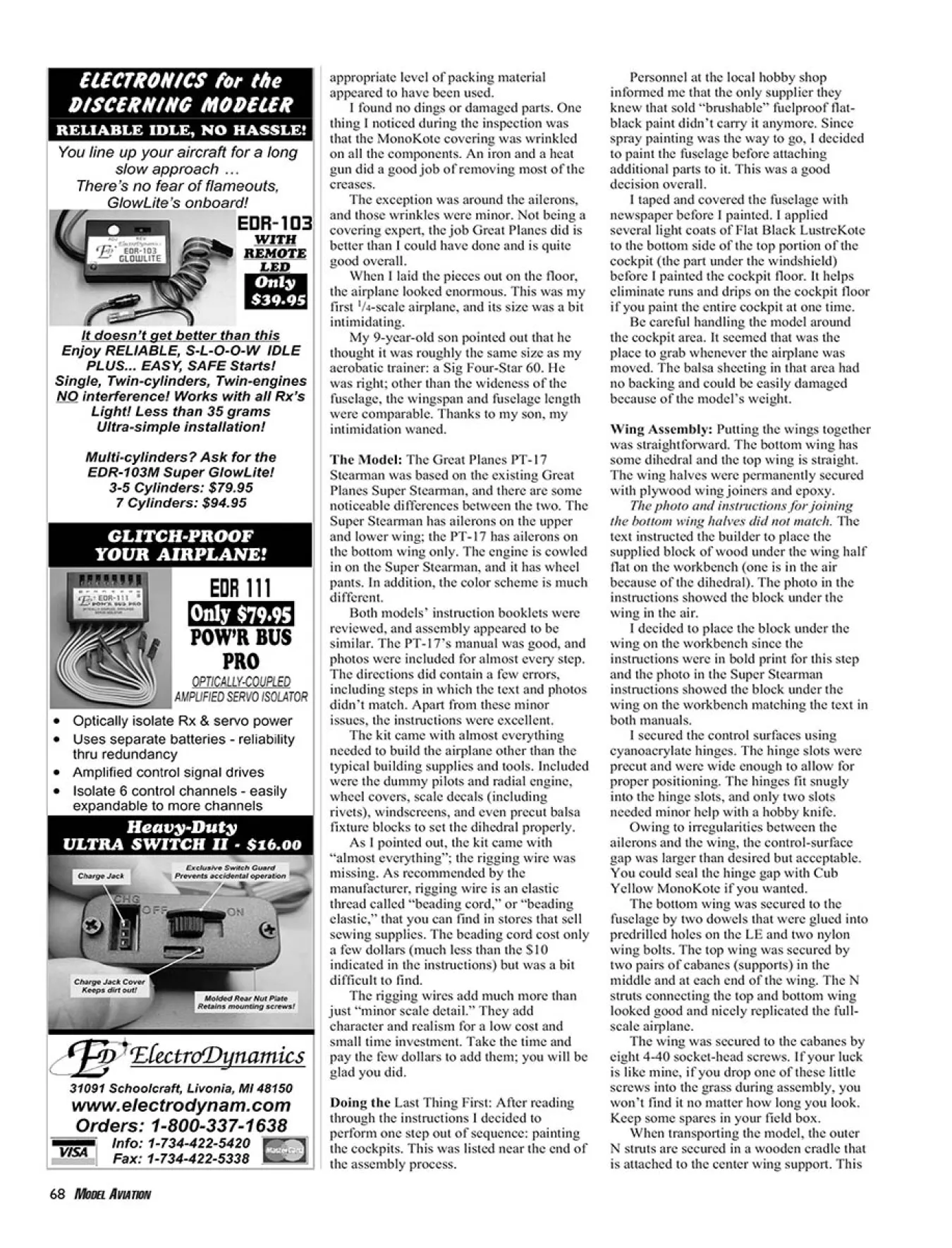

