
January 2005 131
Bob Kopski, 25 West End Dr., Lansdale PA 19446
RADIO CONTROL ELECTRICS
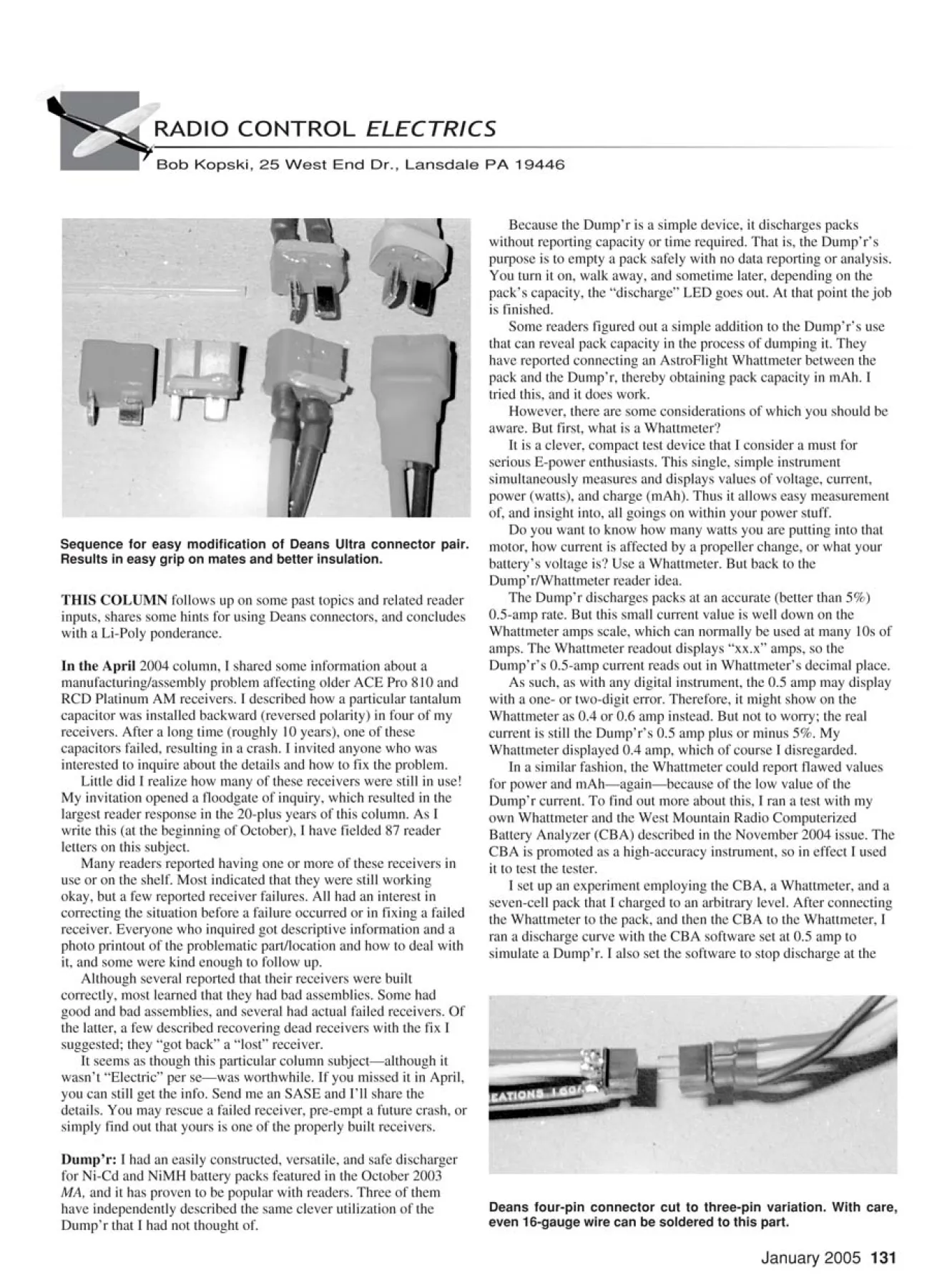
Deans four-pin connector cut to three-pin variation. With care,
even 16-gauge wire can be soldered to this part.
Sequence for easy modification of Deans Ultra connector pair.
Results in easy grip on mates and better insulation.
THIS COLUMN follows up on some past topics and related reader
inputs, shares some hints for using Deans connectors, and concludes
with a Li-Poly ponderance.
In the April 2004 column, I shared some information about a
manufacturing/assembly problem affecting older ACE Pro 810 and
RCD Platinum AM receivers. I described how a particular tantalum
capacitor was installed backward (reversed polarity) in four of my
receivers. After a long time (roughly 10 years), one of these
capacitors failed, resulting in a crash. I invited anyone who was
interested to inquire about the details and how to fix the problem.
Little did I realize how many of these receivers were still in use!
My invitation opened a floodgate of inquiry, which resulted in the
largest reader response in the 20-plus years of this column. As I
write this (at the beginning of October), I have fielded 87 reader
letters on this subject.
Many readers reported having one or more of these receivers in
use or on the shelf. Most indicated that they were still working
okay, but a few reported receiver failures. All had an interest in
correcting the situation before a failure occurred or in fixing a failed
receiver. Everyone who inquired got descriptive information and a
photo printout of the problematic part/location and how to deal with
it, and some were kind enough to follow up.
Although several reported that their receivers were built
correctly, most learned that they had bad assemblies. Some had
good and bad assemblies, and several had actual failed receivers. Of
the latter, a few described recovering dead receivers with the fix I
suggested; they “got back” a “lost” receiver.
It seems as though this particular column subject—although it
wasn’t “Electric” per se—was worthwhile. If you missed it in April,
you can still get the info. Send me an SASE and I’ll share the
details. You may rescue a failed receiver, pre-empt a future crash, or
simply find out that yours is one of the properly built receivers.
Dump’r: I had an easily constructed, versatile, and safe discharger
for Ni-Cd and NiMH battery packs featured in the October 2003
MA, and it has proven to be popular with readers. Three of them
have independently described the same clever utilization of the
Dump’r that I had not thought of.
Because the Dump’r is a simple device, it discharges packs
without reporting capacity or time required. That is, the Dump’r’s
purpose is to empty a pack safely with no data reporting or analysis.
You turn it on, walk away, and sometime later, depending on the
pack’s capacity, the “discharge” LED goes out. At that point the job
is finished.
Some readers figured out a simple addition to the Dump’r’s use
that can reveal pack capacity in the process of dumping it. They
have reported connecting an AstroFlight Whattmeter between the
pack and the Dump’r, thereby obtaining pack capacity in mAh. I
tried this, and it does work.
However, there are some considerations of which you should be
aware. But first, what is a Whattmeter?
It is a clever, compact test device that I consider a must for
serious E-power enthusiasts. This single, simple instrument
simultaneously measures and displays values of voltage, current,
power (watts), and charge (mAh). Thus it allows easy measurement
of, and insight into, all goings on within your power stuff.
Do you want to know how many watts you are putting into that
motor, how current is affected by a propeller change, or what your
battery’s voltage is? Use a Whattmeter. But back to the
Dump’r/Whattmeter reader idea.
The Dump’r discharges packs at an accurate (better than 5%)
0.5-amp rate. But this small current value is well down on the
Whattmeter amps scale, which can normally be used at many 10s of
amps. The Whattmeter readout displays “xx.x” amps, so the
Dump’r’s 0.5-amp current reads out in Whattmeter’s decimal place.
As such, as with any digital instrument, the 0.5 amp may display
with a one- or two-digit error. Therefore, it might show on the
Whattmeter as 0.4 or 0.6 amp instead. But not to worry; the real
current is still the Dump’r’s 0.5 amp plus or minus 5%. My
Whattmeter displayed 0.4 amp, which of course I disregarded.
In a similar fashion, the Whattmeter could report flawed values
for power and mAh—again—because of the low value of the
Dump’r current. To find out more about this, I ran a test with my
own Whattmeter and the West Mountain Radio Computerized
Battery Analyzer (CBA) described in the November 2004 issue. The
CBA is promoted as a high-accuracy instrument, so in effect I used
it to test the tester.
I set up an experiment employing the CBA, a Whattmeter, and a
seven-cell pack that I charged to an arbitrary level. After connecting
the Whattmeter to the pack, and then the CBA to the Whattmeter, I
ran a discharge curve with the CBA software set at 0.5 amp to
simulate a Dump’r. I also set the software to stop discharge at the
equivalent of 0.9 volt per cell, or 6.3 volts
for the pack—as Dump’r does. Thus in this
experiment my CBA was my substitute
Dump’r.
The test run took nearly 50 minutes and
automatically terminated when the pack
voltage fell to 6.3. The CBA software
reported 0.41 mAh, and the Whattmeter
indicated 0.384 mAh. This is good
agreement, given that absolute accuracy is
not a driving issue in this application. The
run-to-run repeatability is what really
matters. You can use a Whattmeter and a
Dump’r this way and keep tabs on your
packs with confidence.
Be aware that the Whattmeter does take
some small current (several milliamps) from
the pack for its own operation. If left
connected after the Dump’r shuts down, this
little instrument current will eventually drain
the pack extremely low, resulting in the
Whattmeter itself shutting down. Of course
the acquired data will be lost.
The time required for this to happen
depends on many variables, including cell
count, pack capacity, and pack condition,
and it can be as short as several minutes.
You don’t have to sit there watching the
process, but you do need to check in often
enough to catch the results before they
disappear!
Remember that the Dump’r is for Ni-Cd
and NiMH packs—not Li-Poly. Thanks to
those readers who told me about this clever
technique.
Photos this month illustrate unconventional
applications and modifications to Deans
connectors that I have found incredibly
useful. A couple of pictures show the use of
a modified four-pin Deans connector to
mate a brushless motor with its ESC.
I cut the fourth (widest-spaced) pins off,
leaving the three equally spaced male pins
and female sockets in place. In effect, I cut
down a four-pin connector set to make it a
three-pin set. (No, it’s not the same as using
a three-pin Deans to begin with; those pins
are not equidistant!)
I used this modified connector as shown,
to mate three brushless motor/ESC wires.
The neat thing about this is that the
connector pair can be rotated 180° to reverse
motor rotational direction; that is why the
three equidistant pins are needed. This is
simple, low-cost, compact, and lightweight!
The Deans connector body itself can
easily be cut with a Zona saw. A little care
results in a neat connector pair. The
connector set shown is installed in an AXI
221226/Castle Creations Phoenix-25
hookup. The peak system current is roughly
13 amps. I’m guessing that this connector
approach would continue to work well
upward of 20 amps, but I haven’t tried it.
Another photo shows a Deans Ultra
modification I’m using. If you’ve ever tried
to separate a tightly mated Ultra connector
pair, you know it can be challenging. One
often has to tug on the wires to do this job—
not a good idea. However, I’ve found a way
to greatly improve this frustrating situation.
You can modify Deans Ultra connectors
by adding “grips” to them as I have. You do
this by hot-melt gluing short pieces of 1⁄16-
inch-diameter plastic tube or rod material to
the connector sides just inside the wire end.
Put some hot-melt glue on the connector
surface, and press some plastic rod in place
on each side of the connector body one side
at a time. Trim the glued pieces at an angle
so that there is no abrupt protrusion of the
rod material at the connector edges.
When this is done, add more hot-melt
glue over the connector body at, and
forward of, the plastic pieces. When that
cools, add some 1⁄2-inch heat-shrink tubing
over all, and use a covering gun to shrink it
tight. This process does briefly reflow the
hot-melt glue underneath, and this seems to
do a great job of keeping everything in
place. The result is two opposing “bumps”
on the Deans Ultra connector body parts that
permit easy finger grip and separation of a
mated pair.
Try this simple modification; I believe
you will find it worthwhile. So far I’ve used
Goldenrod wire pushrod guide tubing and
some Plastruct rod
material for the
“bumps.” I suspect
that many other
items would work
well in this
application.
Li-Poly batteries
are everywhere—
and they certainly do
bring a whole new
level of performance
to E-power
aeromodeling. I have
many in enjoyable
use but have come to
ponder one
application aspect.
A common
advisory when using
Li-Poly batteries is to make sure not to
“short” the output of any cells or packs. The
suggestion is that “very bad things” could
result if this happens. I don’t know if this
consequence is true or not, and I’ve been
careful to avoid any risk. Or have I? How
about you?
Please recall the August 2004 column,
wherein I described the use of arming
switches with brushless controllers. I noted
how these ESCs typically have large-value
capacitors on the power wire inputs and how
these capacitors represent a momentary
short upon applying battery voltage.
In particular, I described how the
sparking and arcing that occurs upon arming
switch closure can easily destroy the switch
itself. I further noted that this same sparking
and arcing occurs on powering up when
using connectors as a “switch.”
Consider connecting a Li-Poly pack to
such a controller. I know that when I do so
via connectors, a clear, crisp spark
momentarily appears. No matter how you
look at it, this is a momentary short.
My ponderance is, how short can a short
be without being a short? You may want to
read that again. It queries exactly how long
(timewise) a short (circuit) can last before
the advisory of not shorting Li-Poly
batteries is violated.
And does a recurring series of short
shorts (as in the preceding, every time I
power up) accumulate in effect; i.e., do they
eventually become collectively long enough
to become that feared reality of shorting a
Li-Poly battery cell or pack? Does anybody
out there know?
Regardless, I am (cautiously) enjoying
the benefits of this battery technology—
always nervous, on edge, and hoping that
the new level of E-flying fun never turns
otherwise. Take care, everyone.
Thus ends the first column of the new year.
Have a great Electric 2005, everyone. And
please enclose an SASE with any
correspondence for which you’d like a reply.
Everyone so doing does get one. MA
132 MODEL AVIATION
Modified Deans connector makes tidy
brushless motor/controller connection
with easy rotation reversal possible.
Test setup using Astro Whattmeter to measure pack capacity
during “dumping.” A CBA temporarily substitutes for Dump’r.
Edition: Model Aviation - 2005/01
Page Numbers: 131,132

Edition: Model Aviation - 2005/01
Page Numbers: 131,132
January 2005 131
Bob Kopski, 25 West End Dr., Lansdale PA 19446
RADIO CONTROL ELECTRICS
Deans four-pin connector cut to three-pin variation. With care,
even 16-gauge wire can be soldered to this part.
Sequence for easy modification of Deans Ultra connector pair.
Results in easy grip on mates and better insulation.
THIS COLUMN follows up on some past topics and related reader
inputs, shares some hints for using Deans connectors, and concludes
with a Li-Poly ponderance.
In the April 2004 column, I shared some information about a
manufacturing/assembly problem affecting older ACE Pro 810 and
RCD Platinum AM receivers. I described how a particular tantalum
capacitor was installed backward (reversed polarity) in four of my
receivers. After a long time (roughly 10 years), one of these
capacitors failed, resulting in a crash. I invited anyone who was
interested to inquire about the details and how to fix the problem.
Little did I realize how many of these receivers were still in use!
My invitation opened a floodgate of inquiry, which resulted in the
largest reader response in the 20-plus years of this column. As I
write this (at the beginning of October), I have fielded 87 reader
letters on this subject.
Many readers reported having one or more of these receivers in
use or on the shelf. Most indicated that they were still working
okay, but a few reported receiver failures. All had an interest in
correcting the situation before a failure occurred or in fixing a failed
receiver. Everyone who inquired got descriptive information and a
photo printout of the problematic part/location and how to deal with
it, and some were kind enough to follow up.
Although several reported that their receivers were built
correctly, most learned that they had bad assemblies. Some had
good and bad assemblies, and several had actual failed receivers. Of
the latter, a few described recovering dead receivers with the fix I
suggested; they “got back” a “lost” receiver.
It seems as though this particular column subject—although it
wasn’t “Electric” per se—was worthwhile. If you missed it in April,
you can still get the info. Send me an SASE and I’ll share the
details. You may rescue a failed receiver, pre-empt a future crash, or
simply find out that yours is one of the properly built receivers.
Dump’r: I had an easily constructed, versatile, and safe discharger
for Ni-Cd and NiMH battery packs featured in the October 2003
MA, and it has proven to be popular with readers. Three of them
have independently described the same clever utilization of the
Dump’r that I had not thought of.
Because the Dump’r is a simple device, it discharges packs
without reporting capacity or time required. That is, the Dump’r’s
purpose is to empty a pack safely with no data reporting or analysis.
You turn it on, walk away, and sometime later, depending on the
pack’s capacity, the “discharge” LED goes out. At that point the job
is finished.
Some readers figured out a simple addition to the Dump’r’s use
that can reveal pack capacity in the process of dumping it. They
have reported connecting an AstroFlight Whattmeter between the
pack and the Dump’r, thereby obtaining pack capacity in mAh. I
tried this, and it does work.
However, there are some considerations of which you should be
aware. But first, what is a Whattmeter?
It is a clever, compact test device that I consider a must for
serious E-power enthusiasts. This single, simple instrument
simultaneously measures and displays values of voltage, current,
power (watts), and charge (mAh). Thus it allows easy measurement
of, and insight into, all goings on within your power stuff.
Do you want to know how many watts you are putting into that
motor, how current is affected by a propeller change, or what your
battery’s voltage is? Use a Whattmeter. But back to the
Dump’r/Whattmeter reader idea.
The Dump’r discharges packs at an accurate (better than 5%)
0.5-amp rate. But this small current value is well down on the
Whattmeter amps scale, which can normally be used at many 10s of
amps. The Whattmeter readout displays “xx.x” amps, so the
Dump’r’s 0.5-amp current reads out in Whattmeter’s decimal place.
As such, as with any digital instrument, the 0.5 amp may display
with a one- or two-digit error. Therefore, it might show on the
Whattmeter as 0.4 or 0.6 amp instead. But not to worry; the real
current is still the Dump’r’s 0.5 amp plus or minus 5%. My
Whattmeter displayed 0.4 amp, which of course I disregarded.
In a similar fashion, the Whattmeter could report flawed values
for power and mAh—again—because of the low value of the
Dump’r current. To find out more about this, I ran a test with my
own Whattmeter and the West Mountain Radio Computerized
Battery Analyzer (CBA) described in the November 2004 issue. The
CBA is promoted as a high-accuracy instrument, so in effect I used
it to test the tester.
I set up an experiment employing the CBA, a Whattmeter, and a
seven-cell pack that I charged to an arbitrary level. After connecting
the Whattmeter to the pack, and then the CBA to the Whattmeter, I
ran a discharge curve with the CBA software set at 0.5 amp to
simulate a Dump’r. I also set the software to stop discharge at the
equivalent of 0.9 volt per cell, or 6.3 volts
for the pack—as Dump’r does. Thus in this
experiment my CBA was my substitute
Dump’r.
The test run took nearly 50 minutes and
automatically terminated when the pack
voltage fell to 6.3. The CBA software
reported 0.41 mAh, and the Whattmeter
indicated 0.384 mAh. This is good
agreement, given that absolute accuracy is
not a driving issue in this application. The
run-to-run repeatability is what really
matters. You can use a Whattmeter and a
Dump’r this way and keep tabs on your
packs with confidence.
Be aware that the Whattmeter does take
some small current (several milliamps) from
the pack for its own operation. If left
connected after the Dump’r shuts down, this
little instrument current will eventually drain
the pack extremely low, resulting in the
Whattmeter itself shutting down. Of course
the acquired data will be lost.
The time required for this to happen
depends on many variables, including cell
count, pack capacity, and pack condition,
and it can be as short as several minutes.
You don’t have to sit there watching the
process, but you do need to check in often
enough to catch the results before they
disappear!
Remember that the Dump’r is for Ni-Cd
and NiMH packs—not Li-Poly. Thanks to
those readers who told me about this clever
technique.
Photos this month illustrate unconventional
applications and modifications to Deans
connectors that I have found incredibly
useful. A couple of pictures show the use of
a modified four-pin Deans connector to
mate a brushless motor with its ESC.
I cut the fourth (widest-spaced) pins off,
leaving the three equally spaced male pins
and female sockets in place. In effect, I cut
down a four-pin connector set to make it a
three-pin set. (No, it’s not the same as using
a three-pin Deans to begin with; those pins
are not equidistant!)
I used this modified connector as shown,
to mate three brushless motor/ESC wires.
The neat thing about this is that the
connector pair can be rotated 180° to reverse
motor rotational direction; that is why the
three equidistant pins are needed. This is
simple, low-cost, compact, and lightweight!
The Deans connector body itself can
easily be cut with a Zona saw. A little care
results in a neat connector pair. The
connector set shown is installed in an AXI
221226/Castle Creations Phoenix-25
hookup. The peak system current is roughly
13 amps. I’m guessing that this connector
approach would continue to work well
upward of 20 amps, but I haven’t tried it.
Another photo shows a Deans Ultra
modification I’m using. If you’ve ever tried
to separate a tightly mated Ultra connector
pair, you know it can be challenging. One
often has to tug on the wires to do this job—
not a good idea. However, I’ve found a way
to greatly improve this frustrating situation.
You can modify Deans Ultra connectors
by adding “grips” to them as I have. You do
this by hot-melt gluing short pieces of 1⁄16-
inch-diameter plastic tube or rod material to
the connector sides just inside the wire end.
Put some hot-melt glue on the connector
surface, and press some plastic rod in place
on each side of the connector body one side
at a time. Trim the glued pieces at an angle
so that there is no abrupt protrusion of the
rod material at the connector edges.
When this is done, add more hot-melt
glue over the connector body at, and
forward of, the plastic pieces. When that
cools, add some 1⁄2-inch heat-shrink tubing
over all, and use a covering gun to shrink it
tight. This process does briefly reflow the
hot-melt glue underneath, and this seems to
do a great job of keeping everything in
place. The result is two opposing “bumps”
on the Deans Ultra connector body parts that
permit easy finger grip and separation of a
mated pair.
Try this simple modification; I believe
you will find it worthwhile. So far I’ve used
Goldenrod wire pushrod guide tubing and
some Plastruct rod
material for the
“bumps.” I suspect
that many other
items would work
well in this
application.
Li-Poly batteries
are everywhere—
and they certainly do
bring a whole new
level of performance
to E-power
aeromodeling. I have
many in enjoyable
use but have come to
ponder one
application aspect.
A common
advisory when using
Li-Poly batteries is to make sure not to
“short” the output of any cells or packs. The
suggestion is that “very bad things” could
result if this happens. I don’t know if this
consequence is true or not, and I’ve been
careful to avoid any risk. Or have I? How
about you?
Please recall the August 2004 column,
wherein I described the use of arming
switches with brushless controllers. I noted
how these ESCs typically have large-value
capacitors on the power wire inputs and how
these capacitors represent a momentary
short upon applying battery voltage.
In particular, I described how the
sparking and arcing that occurs upon arming
switch closure can easily destroy the switch
itself. I further noted that this same sparking
and arcing occurs on powering up when
using connectors as a “switch.”
Consider connecting a Li-Poly pack to
such a controller. I know that when I do so
via connectors, a clear, crisp spark
momentarily appears. No matter how you
look at it, this is a momentary short.
My ponderance is, how short can a short
be without being a short? You may want to
read that again. It queries exactly how long
(timewise) a short (circuit) can last before
the advisory of not shorting Li-Poly
batteries is violated.
And does a recurring series of short
shorts (as in the preceding, every time I
power up) accumulate in effect; i.e., do they
eventually become collectively long enough
to become that feared reality of shorting a
Li-Poly battery cell or pack? Does anybody
out there know?
Regardless, I am (cautiously) enjoying
the benefits of this battery technology—
always nervous, on edge, and hoping that
the new level of E-flying fun never turns
otherwise. Take care, everyone.
Thus ends the first column of the new year.
Have a great Electric 2005, everyone. And
please enclose an SASE with any
correspondence for which you’d like a reply.
Everyone so doing does get one. MA
132 MODEL AVIATION
Modified Deans connector makes tidy
brushless motor/controller connection
with easy rotation reversal possible.
Test setup using Astro Whattmeter to measure pack capacity
during “dumping.” A CBA temporarily substitutes for Dump’r.

