
Giant Scale ARF finer points
April 2009 133
[[email protected]]
Radio Control Scale Aerobatics John Glezellis
Also included in this column:
• Firewall installation
• Correct hinge-installation
method
• Neat control horns
A 1/8-inch pilot hole has been drilled for the
10-32 control-horn bolt. Gradually increase
the drill bit’s diameter until it is a touch
smaller than the 10-32 size, so it can be
threaded before installing the bolt.
Remember to use a pencil to find the
centers of the servo mounting screws. Then
drill a 1/16-inch pilot hole and thread the
servo screw in place.
Using the methods described in the column, the horizontal stabilizer is rested so that the
hinge glue can dry properly and not run into the open framework.
After the Hangar 9 Angle Pro was zeroed at
the top of the motor box, the author
rotated it 90° and rested it vertically on the
firewall. When it reads -90.0°, you are
guaranteed that the firewall has 0° of
upthrust and downthrust.
I RECENTLY BEGAN the assembly
process of my Thunder Tiger 40% Extra 260.
This is a well-built model and is one of the
best “almost-ready-to-flys” I have seen thus
far. While building this airplane, I found a
few key areas that I would like to discuss,
since many of these steps are required by
most giant-scale ARFs on the market today.
To begin, I will show you how to check
the thrust of your firewall when you need to
install the firewall yourself. Then I will show
you how to properly hinge a given surface and
how to drill for control-horn bolts. Let’s
begin.
Installing the Firewall: Because quite a few
giant-scale engine options exist on the market,
some manufacturers leave the firewall
installation to the builder. On this airplane, I
decided to use the Desert Aircraft DA-170
power plant.
After I determined where the firewall
would be positioned with regards to depth, I
wanted to check the thrust to make sure no
upthrust or downthrust existed (as the right
thrust is predetermined).
To do that, I used the Hangar 9 Angle Pro.
If you have been following my columns, you
may remember this tool; I used it in the last
column to check control-surface deflection.
Once the depth of the firewall was set, I
needed to make sure that it was not angled; I
wanted to make sure that no upthrust or
downthrust was present. To do this, I took the
“clips” off of the Angle Pro tool so that it was
04sig5.QXD 2/24/09 9:36 AM Page 133
134 MODEL AVIATION
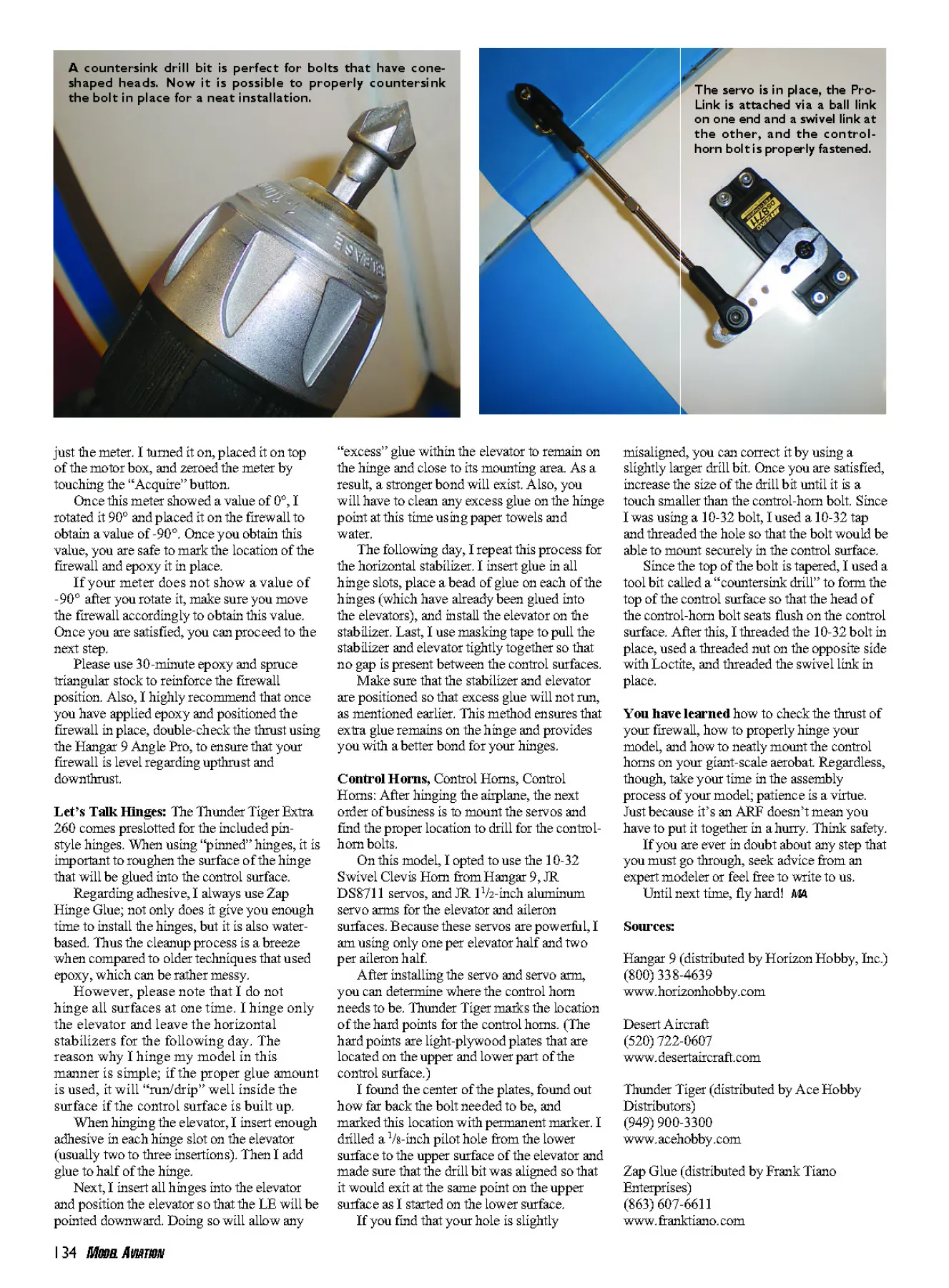
The servo is in place, the Pro-
Link is attached via a ball link
on one end and a swivel link at
the other, and the controlhorn
bolt is properly fastened.
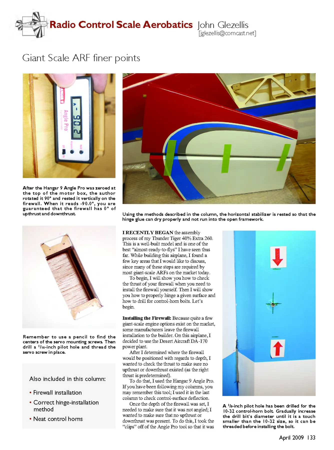
A countersink drill bit is perfect for bolts that have coneshaped
heads. Now it is possible to properly countersink
the bolt in place for a neat installation.
just the meter. I turned it on, placed it on top
of the motor box, and zeroed the meter by
touching the “Acquire” button.
Once this meter showed a value of 0°, I
rotated it 90° and placed it on the firewall to
obtain a value of -90°. Once you obtain this
value, you are safe to mark the location of the
firewall and epoxy it in place.
If your meter does not show a value of
-90° after you rotate it, make sure you move
the firewall accordingly to obtain this value.
Once you are satisfied, you can proceed to the
next step.
Please use 30-minute epoxy and spruce
triangular stock to reinforce the firewall
position. Also, I highly recommend that once
you have applied epoxy and positioned the
firewall in place, double-check the thrust using
the Hangar 9 Angle Pro, to ensure that your
firewall is level regarding upthrust and
downthrust.
Let’s Talk Hinges: The Thunder Tiger Extra
260 comes preslotted for the included pinstyle
hinges. When using “pinned” hinges, it is
important to roughen the surface of the hinge
that will be glued into the control surface.
Regarding adhesive, I always use Zap
Hinge Glue; not only does it give you enough
time to install the hinges, but it is also waterbased.
Thus the cleanup process is a breeze
when compared to older techniques that used
epoxy, which can be rather messy.
However, please note that I do not
hinge all surfaces at one time. I hinge only
the elevator and leave the horizontal
stabilizers for the following day. The
reason why I hinge my model in this
manner is simple; if the proper glue amount
is used, it will “run/drip” well inside the
surface if the control surface is built up.
When hinging the elevator, I insert enough
adhesive in each hinge slot on the elevator
(usually two to three insertions). Then I add
glue to half of the hinge.
Next, I insert all hinges into the elevator
and position the elevator so that the LE will be
pointed downward. Doing so will allow any
“excess” glue within the elevator to remain on
the hinge and close to its mounting area. As a
result, a stronger bond will exist. Also, you
will have to clean any excess glue on the hinge
point at this time using paper towels and
water.
The following day, I repeat this process for
the horizontal stabilizer. I insert glue in all
hinge slots, place a bead of glue on each of the
hinges (which have already been glued into
the elevators), and install the elevator on the
stabilizer. Last, I use masking tape to pull the
stabilizer and elevator tightly together so that
no gap is present between the control surfaces.
Make sure that the stabilizer and elevator
are positioned so that excess glue will not run,
as mentioned earlier. This method ensures that
extra glue remains on the hinge and provides
you with a better bond for your hinges.
Control Horns, Control Horns, Control
Horns: After hinging the airplane, the next
order of business is to mount the servos and
find the proper location to drill for the controlhorn
bolts.
On this model, I opted to use the 10-32
Swivel Clevis Horn from Hangar 9, JR
DS8711 servos, and JR 11/2-inch aluminum
servo arms for the elevator and aileron
surfaces. Because these servos are powerful, I
am using only one per elevator half and two
per aileron half.
After installing the servo and servo arm,
you can determine where the control horn
needs to be. Thunder Tiger marks the location
of the hard points for the control horns. (The
hard points are light-plywood plates that are
located on the upper and lower part of the
control surface.)
I found the center of the plates, found out
how far back the bolt needed to be, and
marked this location with permanent marker. I
drilled a 1/8-inch pilot hole from the lower
surface to the upper surface of the elevator and
made sure that the drill bit was aligned so that
it would exit at the same point on the upper
surface as I started on the lower surface.
If you find that your hole is slightly
misaligned, you can correct it by using a
slightly larger drill bit. Once you are satisfied,
increase the size of the drill bit until it is a
touch smaller than the control-horn bolt. Since
I was using a 10-32 bolt, I used a 10-32 tap
and threaded the hole so that the bolt would be
able to mount securely in the control surface.
Since the top of the bolt is tapered, I used a
tool bit called a “countersink drill” to form the
top of the control surface so that the head of
the control-horn bolt seats flush on the control
surface. After this, I threaded the 10-32 bolt in
place, used a threaded nut on the opposite side
with Loctite, and threaded the swivel link in
place.
You have learned how to check the thrust of
your firewall, how to properly hinge your
model, and how to neatly mount the control
horns on your giant-scale aerobat. Regardless,
though, take your time in the assembly
process of your model; patience is a virtue.
Just because it’s an ARF doesn’t mean you
have to put it together in a hurry. Think safety.
If you are ever in doubt about any step that
you must go through, seek advice from an
expert modeler or feel free to write to us.
Until next time, fly hard! MA
Sources:
Hangar 9 (distributed by Horizon Hobby, Inc.)
(800) 338-4639
www.horizonhobby.com
Desert Aircraft
(520) 722-0607
www.desertaircraft.com
Thunder Tiger (distributed by Ace Hobby
Distributors)
(949) 900-3300
www.acehobby.com
Zap Glue (distributed by Frank Tiano
Enterprises)
(863) 607-6611
www.franktiano.com
04sig5.QXD 2/24/09 9:36 AM Page 134
Edition: Model Aviation - 2009/04
Page Numbers: 133,134
Edition: Model Aviation - 2009/04
Page Numbers: 133,134
Giant Scale ARF finer points
April 2009 133
[[email protected]]
Radio Control Scale Aerobatics John Glezellis
Also included in this column:
• Firewall installation
• Correct hinge-installation
method
• Neat control horns
A 1/8-inch pilot hole has been drilled for the
10-32 control-horn bolt. Gradually increase
the drill bit’s diameter until it is a touch
smaller than the 10-32 size, so it can be
threaded before installing the bolt.
Remember to use a pencil to find the
centers of the servo mounting screws. Then
drill a 1/16-inch pilot hole and thread the
servo screw in place.
Using the methods described in the column, the horizontal stabilizer is rested so that the
hinge glue can dry properly and not run into the open framework.
After the Hangar 9 Angle Pro was zeroed at
the top of the motor box, the author
rotated it 90° and rested it vertically on the
firewall. When it reads -90.0°, you are
guaranteed that the firewall has 0° of
upthrust and downthrust.
I RECENTLY BEGAN the assembly
process of my Thunder Tiger 40% Extra 260.
This is a well-built model and is one of the
best “almost-ready-to-flys” I have seen thus
far. While building this airplane, I found a
few key areas that I would like to discuss,
since many of these steps are required by
most giant-scale ARFs on the market today.
To begin, I will show you how to check
the thrust of your firewall when you need to
install the firewall yourself. Then I will show
you how to properly hinge a given surface and
how to drill for control-horn bolts. Let’s
begin.
Installing the Firewall: Because quite a few
giant-scale engine options exist on the market,
some manufacturers leave the firewall
installation to the builder. On this airplane, I
decided to use the Desert Aircraft DA-170
power plant.
After I determined where the firewall
would be positioned with regards to depth, I
wanted to check the thrust to make sure no
upthrust or downthrust existed (as the right
thrust is predetermined).
To do that, I used the Hangar 9 Angle Pro.
If you have been following my columns, you
may remember this tool; I used it in the last
column to check control-surface deflection.
Once the depth of the firewall was set, I
needed to make sure that it was not angled; I
wanted to make sure that no upthrust or
downthrust was present. To do this, I took the
“clips” off of the Angle Pro tool so that it was
04sig5.QXD 2/24/09 9:36 AM Page 133
134 MODEL AVIATION
The servo is in place, the Pro-
Link is attached via a ball link
on one end and a swivel link at
the other, and the controlhorn
bolt is properly fastened.
A countersink drill bit is perfect for bolts that have coneshaped
heads. Now it is possible to properly countersink
the bolt in place for a neat installation.
just the meter. I turned it on, placed it on top
of the motor box, and zeroed the meter by
touching the “Acquire” button.
Once this meter showed a value of 0°, I
rotated it 90° and placed it on the firewall to
obtain a value of -90°. Once you obtain this
value, you are safe to mark the location of the
firewall and epoxy it in place.
If your meter does not show a value of
-90° after you rotate it, make sure you move
the firewall accordingly to obtain this value.
Once you are satisfied, you can proceed to the
next step.
Please use 30-minute epoxy and spruce
triangular stock to reinforce the firewall
position. Also, I highly recommend that once
you have applied epoxy and positioned the
firewall in place, double-check the thrust using
the Hangar 9 Angle Pro, to ensure that your
firewall is level regarding upthrust and
downthrust.
Let’s Talk Hinges: The Thunder Tiger Extra
260 comes preslotted for the included pinstyle
hinges. When using “pinned” hinges, it is
important to roughen the surface of the hinge
that will be glued into the control surface.
Regarding adhesive, I always use Zap
Hinge Glue; not only does it give you enough
time to install the hinges, but it is also waterbased.
Thus the cleanup process is a breeze
when compared to older techniques that used
epoxy, which can be rather messy.
However, please note that I do not
hinge all surfaces at one time. I hinge only
the elevator and leave the horizontal
stabilizers for the following day. The
reason why I hinge my model in this
manner is simple; if the proper glue amount
is used, it will “run/drip” well inside the
surface if the control surface is built up.
When hinging the elevator, I insert enough
adhesive in each hinge slot on the elevator
(usually two to three insertions). Then I add
glue to half of the hinge.
Next, I insert all hinges into the elevator
and position the elevator so that the LE will be
pointed downward. Doing so will allow any
“excess” glue within the elevator to remain on
the hinge and close to its mounting area. As a
result, a stronger bond will exist. Also, you
will have to clean any excess glue on the hinge
point at this time using paper towels and
water.
The following day, I repeat this process for
the horizontal stabilizer. I insert glue in all
hinge slots, place a bead of glue on each of the
hinges (which have already been glued into
the elevators), and install the elevator on the
stabilizer. Last, I use masking tape to pull the
stabilizer and elevator tightly together so that
no gap is present between the control surfaces.
Make sure that the stabilizer and elevator
are positioned so that excess glue will not run,
as mentioned earlier. This method ensures that
extra glue remains on the hinge and provides
you with a better bond for your hinges.
Control Horns, Control Horns, Control
Horns: After hinging the airplane, the next
order of business is to mount the servos and
find the proper location to drill for the controlhorn
bolts.
On this model, I opted to use the 10-32
Swivel Clevis Horn from Hangar 9, JR
DS8711 servos, and JR 11/2-inch aluminum
servo arms for the elevator and aileron
surfaces. Because these servos are powerful, I
am using only one per elevator half and two
per aileron half.
After installing the servo and servo arm,
you can determine where the control horn
needs to be. Thunder Tiger marks the location
of the hard points for the control horns. (The
hard points are light-plywood plates that are
located on the upper and lower part of the
control surface.)
I found the center of the plates, found out
how far back the bolt needed to be, and
marked this location with permanent marker. I
drilled a 1/8-inch pilot hole from the lower
surface to the upper surface of the elevator and
made sure that the drill bit was aligned so that
it would exit at the same point on the upper
surface as I started on the lower surface.
If you find that your hole is slightly
misaligned, you can correct it by using a
slightly larger drill bit. Once you are satisfied,
increase the size of the drill bit until it is a
touch smaller than the control-horn bolt. Since
I was using a 10-32 bolt, I used a 10-32 tap
and threaded the hole so that the bolt would be
able to mount securely in the control surface.
Since the top of the bolt is tapered, I used a
tool bit called a “countersink drill” to form the
top of the control surface so that the head of
the control-horn bolt seats flush on the control
surface. After this, I threaded the 10-32 bolt in
place, used a threaded nut on the opposite side
with Loctite, and threaded the swivel link in
place.
You have learned how to check the thrust of
your firewall, how to properly hinge your
model, and how to neatly mount the control
horns on your giant-scale aerobat. Regardless,
though, take your time in the assembly
process of your model; patience is a virtue.
Just because it’s an ARF doesn’t mean you
have to put it together in a hurry. Think safety.
If you are ever in doubt about any step that
you must go through, seek advice from an
expert modeler or feel free to write to us.
Until next time, fly hard! MA
Sources:
Hangar 9 (distributed by Horizon Hobby, Inc.)
(800) 338-4639
www.horizonhobby.com
Desert Aircraft
(520) 722-0607
www.desertaircraft.com
Thunder Tiger (distributed by Ace Hobby
Distributors)
(949) 900-3300
www.acehobby.com
Zap Glue (distributed by Frank Tiano
Enterprises)
(863) 607-6611
www.franktiano.com
04sig5.QXD 2/24/09 9:36 AM Page 134

