
by Ken Johnson
IF YOU ARE the type of FF modeler
who enjoys trying something unique, this
model may be just the thing for you.
Anyone can build a Piper Cub that flies.
Show me someone who can make a
flying wing or a canard fly, and I’ll show
you a real modeler. This is not to say
there’s anything wrong with Piper Cubs,
but the challenge of a radical planform is
intriguing.
I started playing with air-powered
models awhile back. Specifically, I used
the Air Hogs compressed-air motor unit
that is marketed by Spin Master Toys of
Toronto, Canada. This little power plant
puts out a great deal of torque and has a
fair running time.
My first air-powered model was a
standard free-flight tractor style. It flew
quite well and got me hooked on air
power, which is clean and inexpensive
(roughly $15 if you purchase the motor
from Spin Master), and the fuel is free.
It’s hard to beat that! An airplane that
weighs approximately 100 grams total is
ideal. The span would be 30-40 inches.
I have built various models since then,
including the Diamond Gem joined-wing
design, a Dragon Fly, a Butterfly, a scaletype
flying wing, and a Sea Gull. My
latest design also uses the joined-wing
concept, only this time it has an oval
shape.
My first try with this planform flew
well. The problem was that it was built
too light, thus was too prone to warping.
The stabilizer portion began to distort
after several weeks of flying, which
changed the stabilizer’s angle of attack.
The model was rendered damaged and
unflyable in the succeeding weeks.
I decided to try again, but this time I
built the model stronger. The first one
weighed 88 grams, and the new one weighs
110 grams. My earlier plans were handdrawn
and slightly inaccurate in outline
shape. I drew the newest design on the
computer, and it is better.
I made the outlines on my Macintosh
and then photocopied them and enlarged
them to the 35-inch-wingspan size. I redrew
the plans more completely and then got a
same-size copy, which I used to pinhole the
outline shapes. This worked well.
Since the tail of the number two model
is slightly larger (and a bit tail-heavy), it
requires a small amount of ballast at the
nose.
The Ring Wing climbs to the left and
reaches 100-150 feet of altitude before
transitioning to the glide. It requires roughly
1⁄8 inch of right thrust to open up the left
turn. This design has not flown in thermal
air yet, but I’m convinced that it could do so
quite well.
CONSTRUCTION
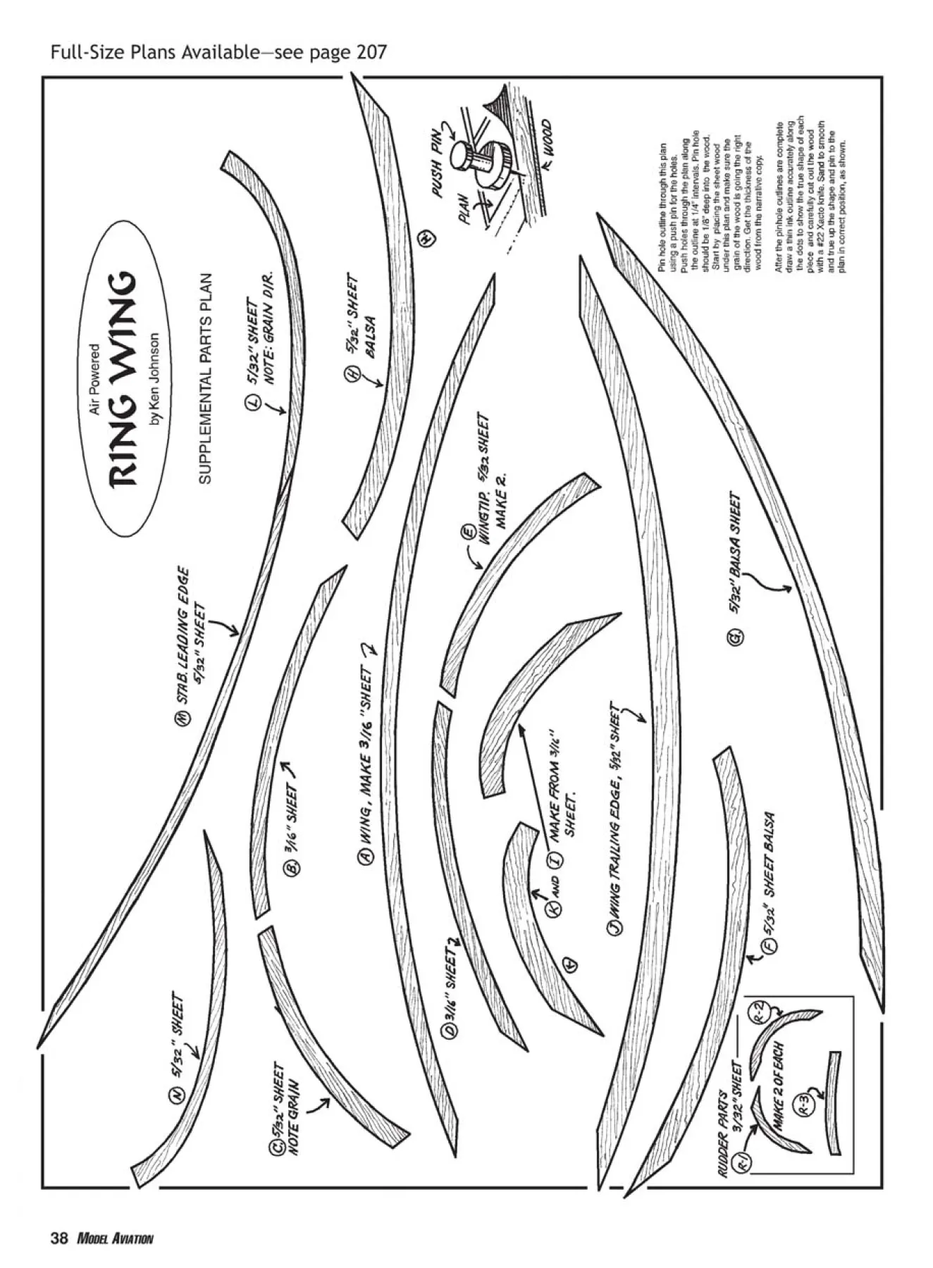
See the plans for the wing and
stabilizer outlines. The wing LE is made
from 3⁄16 sheet, quarter-grain balsa.
Position the wood (with the grain running
lengthwise) under the proper plans outline.
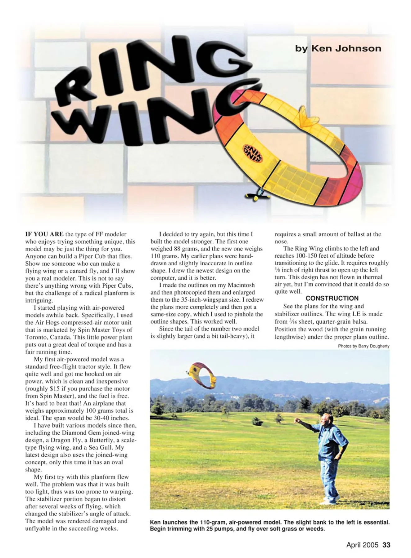
Ken launches the 110-gram, air-powered model. The slight bank to the left is essential.
Begin trimming with 25 pumps, and fly over soft grass or weeds.
Photos by Barry Dougherty
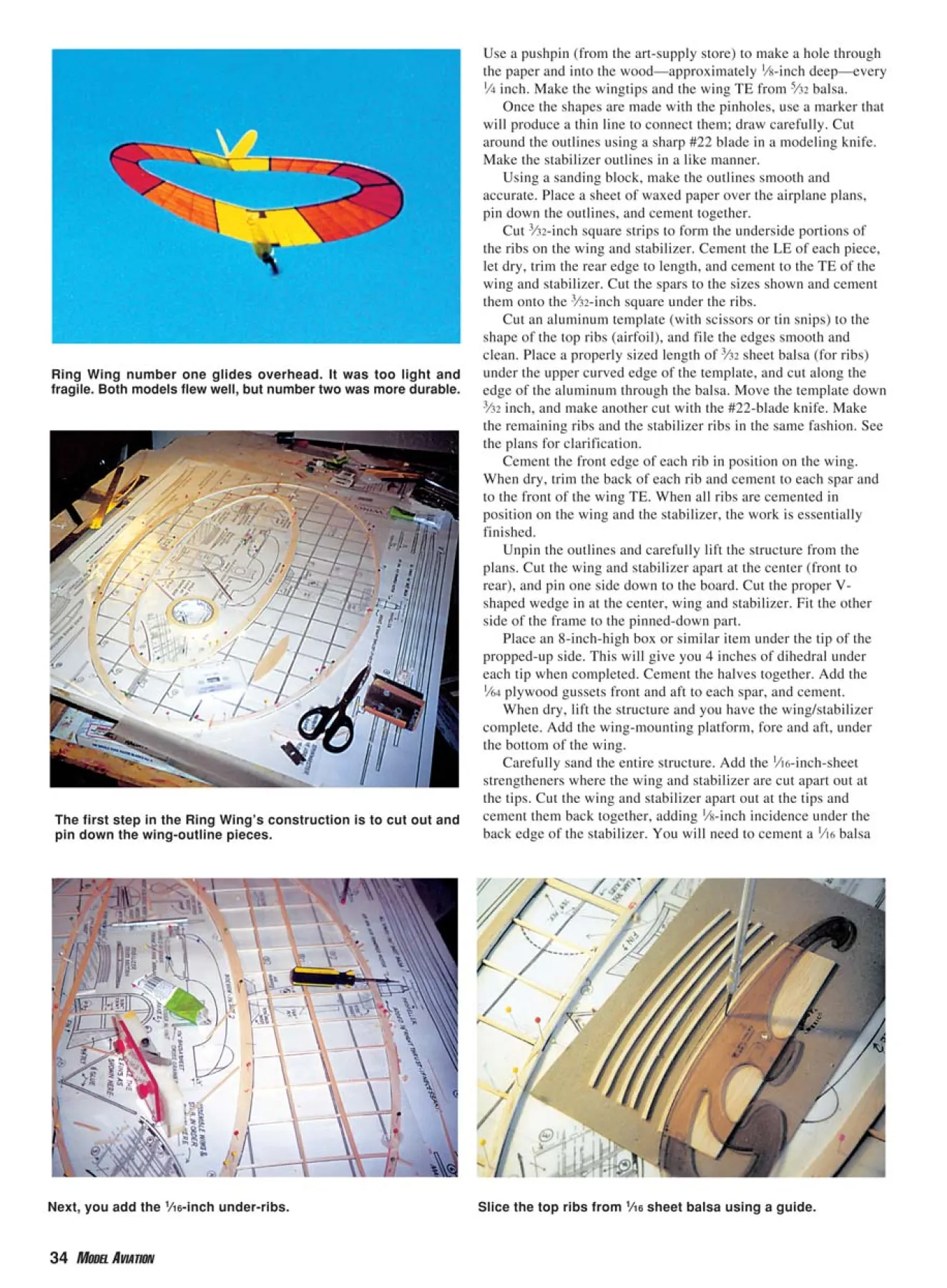
Next, you add the 1⁄16-inch under-ribs.
The first step in the Ring Wing’s construction is to cut out and
pin down the wing-outline pieces.
Slice the top ribs from 1⁄16 sheet balsa using a guide.
Ring Wing number one glides overhead. It was too light and
fragile. Both models flew well, but number two was more durable.
Use a pushpin (from the art-supply store) to make a hole through
the paper and into the wood—approximately 1⁄8-inch deep—every
1⁄4 inch. Make the wingtips and the wing TE from 5⁄32 balsa.
Once the shapes are made with the pinholes, use a marker that
will produce a thin line to connect them; draw carefully. Cut
around the outlines using a sharp #22 blade in a modeling knife.
Make the stabilizer outlines in a like manner.
Using a sanding block, make the outlines smooth and
accurate. Place a sheet of waxed paper over the airplane plans,
pin down the outlines, and cement together.
Cut 3⁄32-inch square strips to form the underside portions of
the ribs on the wing and stabilizer. Cement the LE of each piece,
let dry, trim the rear edge to length, and cement to the TE of the
wing and stabilizer. Cut the spars to the sizes shown and cement
them onto the 3⁄32-inch square under the ribs.
Cut an aluminum template (with scissors or tin snips) to the
shape of the top ribs (airfoil), and file the edges smooth and
clean. Place a properly sized length of 3⁄32 sheet balsa (for ribs)
under the upper curved edge of the template, and cut along the
edge of the aluminum through the balsa. Move the template down
3⁄32 inch, and make another cut with the #22-blade knife. Make
the remaining ribs and the stabilizer ribs in the same fashion. See
the plans for clarification.
Cement the front edge of each rib in position on the wing.
When dry, trim the back of each rib and cement to each spar and
to the front of the wing TE. When all ribs are cemented in
position on the wing and the stabilizer, the work is essentially
finished.
Unpin the outlines and carefully lift the structure from the
plans. Cut the wing and stabilizer apart at the center (front to
rear), and pin one side down to the board. Cut the proper Vshaped
wedge in at the center, wing and stabilizer. Fit the other
side of the frame to the pinned-down part.
Place an 8-inch-high box or similar item under the tip of the
propped-up side. This will give you 4 inches of dihedral under
each tip when completed. Cement the halves together. Add the
1⁄64 plywood gussets front and aft to each spar, and cement.
When dry, lift the structure and you have the wing/stabilizer
complete. Add the wing-mounting platform, fore and aft, under
the bottom of the wing.
Carefully sand the entire structure. Add the 1⁄16-inch-sheet
strengtheners where the wing and stabilizer are cut apart out at
the tips. Cut the wing and stabilizer apart out at the tips and
cement them back together, adding 1⁄8-inch incidence under the
back edge of the stabilizer. You will need to cement a 1⁄16 balsa
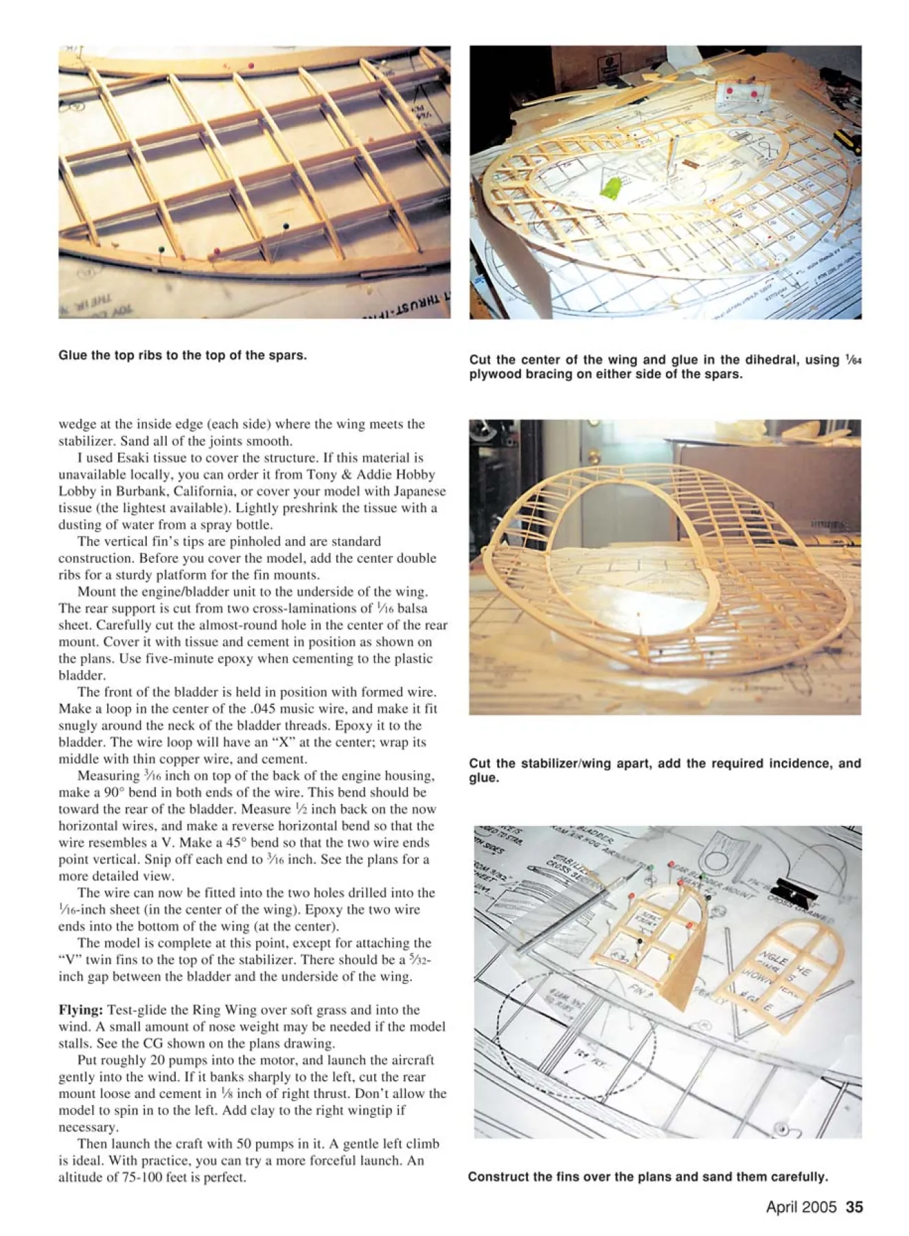
Glue the top ribs to the top of the spars.
wedge at the inside edge (each side) where the wing meets the
stabilizer. Sand all of the joints smooth.
I used Esaki tissue to cover the structure. If this material is
unavailable locally, you can order it from Tony & Addie Hobby
Lobby in Burbank, California, or cover your model with Japanese
tissue (the lightest available). Lightly preshrink the tissue with a
dusting of water from a spray bottle.
The vertical fin’s tips are pinholed and are standard
construction. Before you cover the model, add the center double
ribs for a sturdy platform for the fin mounts.
Mount the engine/bladder unit to the underside of the wing.
The rear support is cut from two cross-laminations of 1⁄16 balsa
sheet. Carefully cut the almost-round hole in the center of the rear
mount. Cover it with tissue and cement in position as shown on
the plans. Use five-minute epoxy when cementing to the plastic
bladder.
The front of the bladder is held in position with formed wire.
Make a loop in the center of the .045 music wire, and make it fit
snugly around the neck of the bladder threads. Epoxy it to the
bladder. The wire loop will have an “X” at the center; wrap its
middle with thin copper wire, and cement.
Measuring 3⁄16 inch on top of the back of the engine housing,
make a 90° bend in both ends of the wire. This bend should be
toward the rear of the bladder. Measure 1⁄2 inch back on the now
horizontal wires, and make a reverse horizontal bend so that the
wire resembles a V. Make a 45° bend so that the two wire ends
point vertical. Snip off each end to 3⁄16 inch. See the plans for a
more detailed view.
The wire can now be fitted into the two holes drilled into the
1⁄16-inch sheet (in the center of the wing). Epoxy the two wire
ends into the bottom of the wing (at the center).
The model is complete at this point, except for attaching the
“V” twin fins to the top of the stabilizer. There should be a 5⁄32-
inch gap between the bladder and the underside of the wing.
Flying: Test-glide the Ring Wing over soft grass and into the
wind. A small amount of nose weight may be needed if the model
stalls. See the CG shown on the plans drawing.
Put roughly 20 pumps into the motor, and launch the aircraft
gently into the wind. If it banks sharply to the left, cut the rear
mount loose and cement in 1⁄8 inch of right thrust. Don’t allow the
model to spin in to the left. Add clay to the right wingtip if
necessary.
Then launch the craft with 50 pumps in it. A gentle left climb
is ideal. With practice, you can try a more forceful launch. An
altitude of 75-100 feet is perfect.
Cut the center of the wing and glue in the dihedral, using 1⁄64
plywood bracing on either side of the spars.
Cut the stabilizer/wing apart, add the required incidence, and
glue.
Construct the fins over the plans and sand them carefully.
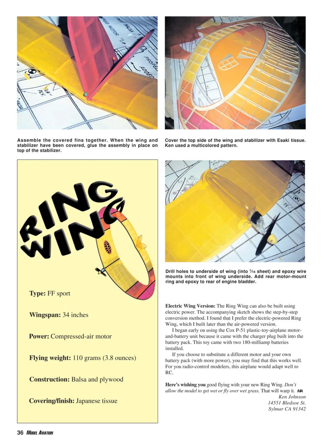
Cover the top side of the wing and stabilizer with Esaki tissue.
Ken used a multicolored pattern.
Drill holes to underside of wing (into 1⁄16 sheet) and epoxy wire
mounts into front of wing underside. Add rear motor-mount
ring and epoxy to rear of engine bladder.
Assemble the covered fins together. When the wing and
stabilizer have been covered, glue the assembly in place on
top of the stabilizer.
Electric Wing Version: The Ring Wing can also be built using
electric power. The accompanying sketch shows the step-by-step
conversion method. I found that I prefer the electric-powered Ring
Wing, which I built later than the air-powered version.
I began early on using the Cox P-51 plastic-toy-airplane motorand-
battery unit because it came with the charger plug built into the
battery pack. This toy came with two 180-milliamp batteries
installed.
If you choose to substitute a different motor and your own
battery pack (with more power), you may find that this works well.
For you radio-control modelers, this airplane would adapt well to
RC.
Here’s wishing you good flying with your new Ring Wing. Don’t
allow the model to get wet or fly over wet grass. That will warp it. MA
Ken Johnson
14551 Bledsoe St.
Sylmar CA 91342
36 MODEL AVIATION
Type: FF sport
Wingspan: 34 inches
Power: Compressed-air motor
Flying weight: 110 grams (3.8 ounces)
Construction: Balsa and plywood
Covering/finish: Japanese tissue
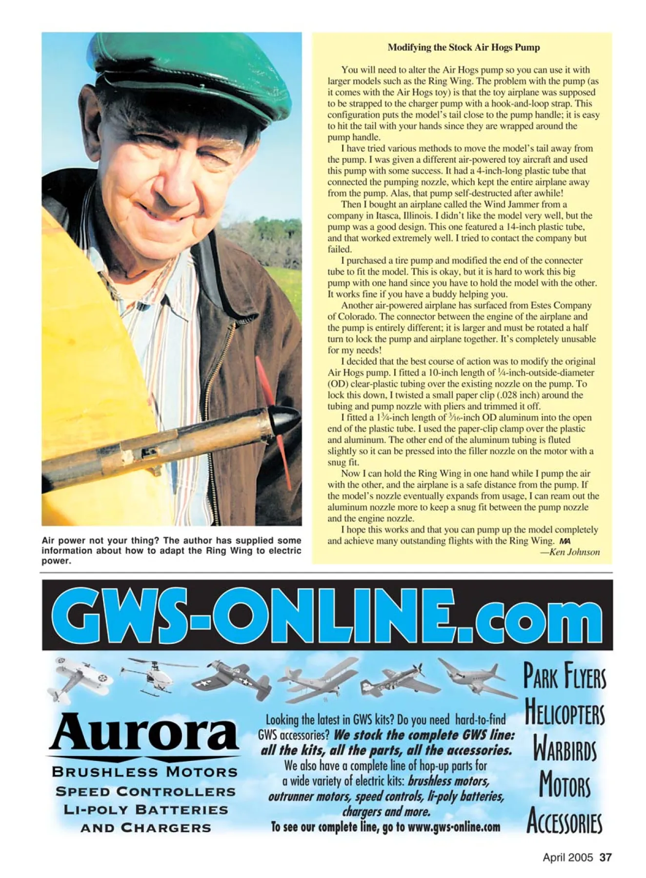
Air power not your thing? The author has supplied some
information about how to adapt the Ring Wing to electric
power.
Modifying the Stock Air Hogs Pump
You will need to alter the Air Hogs pump so you can use it with
larger models such as the Ring Wing. The problem with the pump (as
it comes with the Air Hogs toy) is that the toy airplane was supposed
to be strapped to the charger pump with a hook-and-loop strap. This
configuration puts the model’s tail close to the pump handle; it is easy
to hit the tail with your hands since they are wrapped around the
pump handle.
I have tried various methods to move the model’s tail away from
the pump. I was given a different air-powered toy aircraft and used
this pump with some success. It had a 4-inch-long plastic tube that
connected the pumping nozzle, which kept the entire airplane away
from the pump. Alas, that pump self-destructed after awhile!
Then I bought an airplane called the Wind Jammer from a
company in Itasca, Illinois. I didn’t like the model very well, but the
pump was a good design. This one featured a 14-inch plastic tube,
and that worked extremely well. I tried to contact the company but
failed.
I purchased a tire pump and modified the end of the connecter
tube to fit the model. This is okay, but it is hard to work this big
pump with one hand since you have to hold the model with the other.
It works fine if you have a buddy helping you.
Another air-powered airplane has surfaced from Estes Company
of Colorado. The connector between the engine of the airplane and
the pump is entirely different; it is larger and must be rotated a half
turn to lock the pump and airplane together. It’s completely unusable
for my needs!
I decided that the best course of action was to modify the original
Air Hogs pump. I fitted a 10-inch length of 1⁄4-inch-outside-diameter
(OD) clear-plastic tubing over the existing nozzle on the pump. To
lock this down, I twisted a small paper clip (.028 inch) around the
tubing and pump nozzle with pliers and trimmed it off.
I fitted a 13⁄4-inch length of 3⁄16-inch OD aluminum into the open
end of the plastic tube. I used the paper-clip clamp over the plastic
and aluminum. The other end of the aluminum tubing is fluted
slightly so it can be pressed into the filler nozzle on the motor with a
snug fit.
Now I can hold the Ring Wing in one hand while I pump the air
with the other, and the airplane is a safe distance from the pump. If
the model’s nozzle eventually expands from usage, I can ream out the
aluminum nozzle more to keep a snug fit between the pump nozzle
and the engine nozzle.
I hope this works and that you can pump up the model completely
and achieve many outstanding flights with the Ring Wing. MA
—Ken Johnson
Edition: Model Aviation - 2005/04
Page Numbers: 33,34,35,36,37,38,39,40
Edition: Model Aviation - 2005/04
Page Numbers: 33,34,35,36,37,38,39,40
by Ken Johnson
IF YOU ARE the type of FF modeler
who enjoys trying something unique, this
model may be just the thing for you.
Anyone can build a Piper Cub that flies.
Show me someone who can make a
flying wing or a canard fly, and I’ll show
you a real modeler. This is not to say
there’s anything wrong with Piper Cubs,
but the challenge of a radical planform is
intriguing.
I started playing with air-powered
models awhile back. Specifically, I used
the Air Hogs compressed-air motor unit
that is marketed by Spin Master Toys of
Toronto, Canada. This little power plant
puts out a great deal of torque and has a
fair running time.
My first air-powered model was a
standard free-flight tractor style. It flew
quite well and got me hooked on air
power, which is clean and inexpensive
(roughly $15 if you purchase the motor
from Spin Master), and the fuel is free.
It’s hard to beat that! An airplane that
weighs approximately 100 grams total is
ideal. The span would be 30-40 inches.
I have built various models since then,
including the Diamond Gem joined-wing
design, a Dragon Fly, a Butterfly, a scaletype
flying wing, and a Sea Gull. My
latest design also uses the joined-wing
concept, only this time it has an oval
shape.
My first try with this planform flew
well. The problem was that it was built
too light, thus was too prone to warping.
The stabilizer portion began to distort
after several weeks of flying, which
changed the stabilizer’s angle of attack.
The model was rendered damaged and
unflyable in the succeeding weeks.
I decided to try again, but this time I
built the model stronger. The first one
weighed 88 grams, and the new one weighs
110 grams. My earlier plans were handdrawn
and slightly inaccurate in outline
shape. I drew the newest design on the
computer, and it is better.
I made the outlines on my Macintosh
and then photocopied them and enlarged
them to the 35-inch-wingspan size. I redrew
the plans more completely and then got a
same-size copy, which I used to pinhole the
outline shapes. This worked well.
Since the tail of the number two model
is slightly larger (and a bit tail-heavy), it
requires a small amount of ballast at the
nose.
The Ring Wing climbs to the left and
reaches 100-150 feet of altitude before
transitioning to the glide. It requires roughly
1⁄8 inch of right thrust to open up the left
turn. This design has not flown in thermal
air yet, but I’m convinced that it could do so
quite well.
CONSTRUCTION
See the plans for the wing and
stabilizer outlines. The wing LE is made
from 3⁄16 sheet, quarter-grain balsa.
Position the wood (with the grain running
lengthwise) under the proper plans outline.
Ken launches the 110-gram, air-powered model. The slight bank to the left is essential.
Begin trimming with 25 pumps, and fly over soft grass or weeds.
Photos by Barry Dougherty
Next, you add the 1⁄16-inch under-ribs.
The first step in the Ring Wing’s construction is to cut out and
pin down the wing-outline pieces.
Slice the top ribs from 1⁄16 sheet balsa using a guide.
Ring Wing number one glides overhead. It was too light and
fragile. Both models flew well, but number two was more durable.
Use a pushpin (from the art-supply store) to make a hole through
the paper and into the wood—approximately 1⁄8-inch deep—every
1⁄4 inch. Make the wingtips and the wing TE from 5⁄32 balsa.
Once the shapes are made with the pinholes, use a marker that
will produce a thin line to connect them; draw carefully. Cut
around the outlines using a sharp #22 blade in a modeling knife.
Make the stabilizer outlines in a like manner.
Using a sanding block, make the outlines smooth and
accurate. Place a sheet of waxed paper over the airplane plans,
pin down the outlines, and cement together.
Cut 3⁄32-inch square strips to form the underside portions of
the ribs on the wing and stabilizer. Cement the LE of each piece,
let dry, trim the rear edge to length, and cement to the TE of the
wing and stabilizer. Cut the spars to the sizes shown and cement
them onto the 3⁄32-inch square under the ribs.
Cut an aluminum template (with scissors or tin snips) to the
shape of the top ribs (airfoil), and file the edges smooth and
clean. Place a properly sized length of 3⁄32 sheet balsa (for ribs)
under the upper curved edge of the template, and cut along the
edge of the aluminum through the balsa. Move the template down
3⁄32 inch, and make another cut with the #22-blade knife. Make
the remaining ribs and the stabilizer ribs in the same fashion. See
the plans for clarification.
Cement the front edge of each rib in position on the wing.
When dry, trim the back of each rib and cement to each spar and
to the front of the wing TE. When all ribs are cemented in
position on the wing and the stabilizer, the work is essentially
finished.
Unpin the outlines and carefully lift the structure from the
plans. Cut the wing and stabilizer apart at the center (front to
rear), and pin one side down to the board. Cut the proper Vshaped
wedge in at the center, wing and stabilizer. Fit the other
side of the frame to the pinned-down part.
Place an 8-inch-high box or similar item under the tip of the
propped-up side. This will give you 4 inches of dihedral under
each tip when completed. Cement the halves together. Add the
1⁄64 plywood gussets front and aft to each spar, and cement.
When dry, lift the structure and you have the wing/stabilizer
complete. Add the wing-mounting platform, fore and aft, under
the bottom of the wing.
Carefully sand the entire structure. Add the 1⁄16-inch-sheet
strengtheners where the wing and stabilizer are cut apart out at
the tips. Cut the wing and stabilizer apart out at the tips and
cement them back together, adding 1⁄8-inch incidence under the
back edge of the stabilizer. You will need to cement a 1⁄16 balsa
Glue the top ribs to the top of the spars.
wedge at the inside edge (each side) where the wing meets the
stabilizer. Sand all of the joints smooth.
I used Esaki tissue to cover the structure. If this material is
unavailable locally, you can order it from Tony & Addie Hobby
Lobby in Burbank, California, or cover your model with Japanese
tissue (the lightest available). Lightly preshrink the tissue with a
dusting of water from a spray bottle.
The vertical fin’s tips are pinholed and are standard
construction. Before you cover the model, add the center double
ribs for a sturdy platform for the fin mounts.
Mount the engine/bladder unit to the underside of the wing.
The rear support is cut from two cross-laminations of 1⁄16 balsa
sheet. Carefully cut the almost-round hole in the center of the rear
mount. Cover it with tissue and cement in position as shown on
the plans. Use five-minute epoxy when cementing to the plastic
bladder.
The front of the bladder is held in position with formed wire.
Make a loop in the center of the .045 music wire, and make it fit
snugly around the neck of the bladder threads. Epoxy it to the
bladder. The wire loop will have an “X” at the center; wrap its
middle with thin copper wire, and cement.
Measuring 3⁄16 inch on top of the back of the engine housing,
make a 90° bend in both ends of the wire. This bend should be
toward the rear of the bladder. Measure 1⁄2 inch back on the now
horizontal wires, and make a reverse horizontal bend so that the
wire resembles a V. Make a 45° bend so that the two wire ends
point vertical. Snip off each end to 3⁄16 inch. See the plans for a
more detailed view.
The wire can now be fitted into the two holes drilled into the
1⁄16-inch sheet (in the center of the wing). Epoxy the two wire
ends into the bottom of the wing (at the center).
The model is complete at this point, except for attaching the
“V” twin fins to the top of the stabilizer. There should be a 5⁄32-
inch gap between the bladder and the underside of the wing.
Flying: Test-glide the Ring Wing over soft grass and into the
wind. A small amount of nose weight may be needed if the model
stalls. See the CG shown on the plans drawing.
Put roughly 20 pumps into the motor, and launch the aircraft
gently into the wind. If it banks sharply to the left, cut the rear
mount loose and cement in 1⁄8 inch of right thrust. Don’t allow the
model to spin in to the left. Add clay to the right wingtip if
necessary.
Then launch the craft with 50 pumps in it. A gentle left climb
is ideal. With practice, you can try a more forceful launch. An
altitude of 75-100 feet is perfect.
Cut the center of the wing and glue in the dihedral, using 1⁄64
plywood bracing on either side of the spars.
Cut the stabilizer/wing apart, add the required incidence, and
glue.
Construct the fins over the plans and sand them carefully.
Cover the top side of the wing and stabilizer with Esaki tissue.
Ken used a multicolored pattern.
Drill holes to underside of wing (into 1⁄16 sheet) and epoxy wire
mounts into front of wing underside. Add rear motor-mount
ring and epoxy to rear of engine bladder.
Assemble the covered fins together. When the wing and
stabilizer have been covered, glue the assembly in place on
top of the stabilizer.
Electric Wing Version: The Ring Wing can also be built using
electric power. The accompanying sketch shows the step-by-step
conversion method. I found that I prefer the electric-powered Ring
Wing, which I built later than the air-powered version.
I began early on using the Cox P-51 plastic-toy-airplane motorand-
battery unit because it came with the charger plug built into the
battery pack. This toy came with two 180-milliamp batteries
installed.
If you choose to substitute a different motor and your own
battery pack (with more power), you may find that this works well.
For you radio-control modelers, this airplane would adapt well to
RC.
Here’s wishing you good flying with your new Ring Wing. Don’t
allow the model to get wet or fly over wet grass. That will warp it. MA
Ken Johnson
14551 Bledsoe St.
Sylmar CA 91342
36 MODEL AVIATION
Type: FF sport
Wingspan: 34 inches
Power: Compressed-air motor
Flying weight: 110 grams (3.8 ounces)
Construction: Balsa and plywood
Covering/finish: Japanese tissue
Air power not your thing? The author has supplied some
information about how to adapt the Ring Wing to electric
power.
Modifying the Stock Air Hogs Pump
You will need to alter the Air Hogs pump so you can use it with
larger models such as the Ring Wing. The problem with the pump (as
it comes with the Air Hogs toy) is that the toy airplane was supposed
to be strapped to the charger pump with a hook-and-loop strap. This
configuration puts the model’s tail close to the pump handle; it is easy
to hit the tail with your hands since they are wrapped around the
pump handle.
I have tried various methods to move the model’s tail away from
the pump. I was given a different air-powered toy aircraft and used
this pump with some success. It had a 4-inch-long plastic tube that
connected the pumping nozzle, which kept the entire airplane away
from the pump. Alas, that pump self-destructed after awhile!
Then I bought an airplane called the Wind Jammer from a
company in Itasca, Illinois. I didn’t like the model very well, but the
pump was a good design. This one featured a 14-inch plastic tube,
and that worked extremely well. I tried to contact the company but
failed.
I purchased a tire pump and modified the end of the connecter
tube to fit the model. This is okay, but it is hard to work this big
pump with one hand since you have to hold the model with the other.
It works fine if you have a buddy helping you.
Another air-powered airplane has surfaced from Estes Company
of Colorado. The connector between the engine of the airplane and
the pump is entirely different; it is larger and must be rotated a half
turn to lock the pump and airplane together. It’s completely unusable
for my needs!
I decided that the best course of action was to modify the original
Air Hogs pump. I fitted a 10-inch length of 1⁄4-inch-outside-diameter
(OD) clear-plastic tubing over the existing nozzle on the pump. To
lock this down, I twisted a small paper clip (.028 inch) around the
tubing and pump nozzle with pliers and trimmed it off.
I fitted a 13⁄4-inch length of 3⁄16-inch OD aluminum into the open
end of the plastic tube. I used the paper-clip clamp over the plastic
and aluminum. The other end of the aluminum tubing is fluted
slightly so it can be pressed into the filler nozzle on the motor with a
snug fit.
Now I can hold the Ring Wing in one hand while I pump the air
with the other, and the airplane is a safe distance from the pump. If
the model’s nozzle eventually expands from usage, I can ream out the
aluminum nozzle more to keep a snug fit between the pump nozzle
and the engine nozzle.
I hope this works and that you can pump up the model completely
and achieve many outstanding flights with the Ring Wing. MA
—Ken Johnson
Edition: Model Aviation - 2005/04
Page Numbers: 33,34,35,36,37,38,39,40
by Ken Johnson
IF YOU ARE the type of FF modeler
who enjoys trying something unique, this
model may be just the thing for you.
Anyone can build a Piper Cub that flies.
Show me someone who can make a
flying wing or a canard fly, and I’ll show
you a real modeler. This is not to say
there’s anything wrong with Piper Cubs,
but the challenge of a radical planform is
intriguing.
I started playing with air-powered
models awhile back. Specifically, I used
the Air Hogs compressed-air motor unit
that is marketed by Spin Master Toys of
Toronto, Canada. This little power plant
puts out a great deal of torque and has a
fair running time.
My first air-powered model was a
standard free-flight tractor style. It flew
quite well and got me hooked on air
power, which is clean and inexpensive
(roughly $15 if you purchase the motor
from Spin Master), and the fuel is free.
It’s hard to beat that! An airplane that
weighs approximately 100 grams total is
ideal. The span would be 30-40 inches.
I have built various models since then,
including the Diamond Gem joined-wing
design, a Dragon Fly, a Butterfly, a scaletype
flying wing, and a Sea Gull. My
latest design also uses the joined-wing
concept, only this time it has an oval
shape.
My first try with this planform flew
well. The problem was that it was built
too light, thus was too prone to warping.
The stabilizer portion began to distort
after several weeks of flying, which
changed the stabilizer’s angle of attack.
The model was rendered damaged and
unflyable in the succeeding weeks.
I decided to try again, but this time I
built the model stronger. The first one
weighed 88 grams, and the new one weighs
110 grams. My earlier plans were handdrawn
and slightly inaccurate in outline
shape. I drew the newest design on the
computer, and it is better.
I made the outlines on my Macintosh
and then photocopied them and enlarged
them to the 35-inch-wingspan size. I redrew
the plans more completely and then got a
same-size copy, which I used to pinhole the
outline shapes. This worked well.
Since the tail of the number two model
is slightly larger (and a bit tail-heavy), it
requires a small amount of ballast at the
nose.
The Ring Wing climbs to the left and
reaches 100-150 feet of altitude before
transitioning to the glide. It requires roughly
1⁄8 inch of right thrust to open up the left
turn. This design has not flown in thermal
air yet, but I’m convinced that it could do so
quite well.
CONSTRUCTION
See the plans for the wing and
stabilizer outlines. The wing LE is made
from 3⁄16 sheet, quarter-grain balsa.
Position the wood (with the grain running
lengthwise) under the proper plans outline.
Ken launches the 110-gram, air-powered model. The slight bank to the left is essential.
Begin trimming with 25 pumps, and fly over soft grass or weeds.
Photos by Barry Dougherty
Next, you add the 1⁄16-inch under-ribs.
The first step in the Ring Wing’s construction is to cut out and
pin down the wing-outline pieces.
Slice the top ribs from 1⁄16 sheet balsa using a guide.
Ring Wing number one glides overhead. It was too light and
fragile. Both models flew well, but number two was more durable.
Use a pushpin (from the art-supply store) to make a hole through
the paper and into the wood—approximately 1⁄8-inch deep—every
1⁄4 inch. Make the wingtips and the wing TE from 5⁄32 balsa.
Once the shapes are made with the pinholes, use a marker that
will produce a thin line to connect them; draw carefully. Cut
around the outlines using a sharp #22 blade in a modeling knife.
Make the stabilizer outlines in a like manner.
Using a sanding block, make the outlines smooth and
accurate. Place a sheet of waxed paper over the airplane plans,
pin down the outlines, and cement together.
Cut 3⁄32-inch square strips to form the underside portions of
the ribs on the wing and stabilizer. Cement the LE of each piece,
let dry, trim the rear edge to length, and cement to the TE of the
wing and stabilizer. Cut the spars to the sizes shown and cement
them onto the 3⁄32-inch square under the ribs.
Cut an aluminum template (with scissors or tin snips) to the
shape of the top ribs (airfoil), and file the edges smooth and
clean. Place a properly sized length of 3⁄32 sheet balsa (for ribs)
under the upper curved edge of the template, and cut along the
edge of the aluminum through the balsa. Move the template down
3⁄32 inch, and make another cut with the #22-blade knife. Make
the remaining ribs and the stabilizer ribs in the same fashion. See
the plans for clarification.
Cement the front edge of each rib in position on the wing.
When dry, trim the back of each rib and cement to each spar and
to the front of the wing TE. When all ribs are cemented in
position on the wing and the stabilizer, the work is essentially
finished.
Unpin the outlines and carefully lift the structure from the
plans. Cut the wing and stabilizer apart at the center (front to
rear), and pin one side down to the board. Cut the proper Vshaped
wedge in at the center, wing and stabilizer. Fit the other
side of the frame to the pinned-down part.
Place an 8-inch-high box or similar item under the tip of the
propped-up side. This will give you 4 inches of dihedral under
each tip when completed. Cement the halves together. Add the
1⁄64 plywood gussets front and aft to each spar, and cement.
When dry, lift the structure and you have the wing/stabilizer
complete. Add the wing-mounting platform, fore and aft, under
the bottom of the wing.
Carefully sand the entire structure. Add the 1⁄16-inch-sheet
strengtheners where the wing and stabilizer are cut apart out at
the tips. Cut the wing and stabilizer apart out at the tips and
cement them back together, adding 1⁄8-inch incidence under the
back edge of the stabilizer. You will need to cement a 1⁄16 balsa
Glue the top ribs to the top of the spars.
wedge at the inside edge (each side) where the wing meets the
stabilizer. Sand all of the joints smooth.
I used Esaki tissue to cover the structure. If this material is
unavailable locally, you can order it from Tony & Addie Hobby
Lobby in Burbank, California, or cover your model with Japanese
tissue (the lightest available). Lightly preshrink the tissue with a
dusting of water from a spray bottle.
The vertical fin’s tips are pinholed and are standard
construction. Before you cover the model, add the center double
ribs for a sturdy platform for the fin mounts.
Mount the engine/bladder unit to the underside of the wing.
The rear support is cut from two cross-laminations of 1⁄16 balsa
sheet. Carefully cut the almost-round hole in the center of the rear
mount. Cover it with tissue and cement in position as shown on
the plans. Use five-minute epoxy when cementing to the plastic
bladder.
The front of the bladder is held in position with formed wire.
Make a loop in the center of the .045 music wire, and make it fit
snugly around the neck of the bladder threads. Epoxy it to the
bladder. The wire loop will have an “X” at the center; wrap its
middle with thin copper wire, and cement.
Measuring 3⁄16 inch on top of the back of the engine housing,
make a 90° bend in both ends of the wire. This bend should be
toward the rear of the bladder. Measure 1⁄2 inch back on the now
horizontal wires, and make a reverse horizontal bend so that the
wire resembles a V. Make a 45° bend so that the two wire ends
point vertical. Snip off each end to 3⁄16 inch. See the plans for a
more detailed view.
The wire can now be fitted into the two holes drilled into the
1⁄16-inch sheet (in the center of the wing). Epoxy the two wire
ends into the bottom of the wing (at the center).
The model is complete at this point, except for attaching the
“V” twin fins to the top of the stabilizer. There should be a 5⁄32-
inch gap between the bladder and the underside of the wing.
Flying: Test-glide the Ring Wing over soft grass and into the
wind. A small amount of nose weight may be needed if the model
stalls. See the CG shown on the plans drawing.
Put roughly 20 pumps into the motor, and launch the aircraft
gently into the wind. If it banks sharply to the left, cut the rear
mount loose and cement in 1⁄8 inch of right thrust. Don’t allow the
model to spin in to the left. Add clay to the right wingtip if
necessary.
Then launch the craft with 50 pumps in it. A gentle left climb
is ideal. With practice, you can try a more forceful launch. An
altitude of 75-100 feet is perfect.
Cut the center of the wing and glue in the dihedral, using 1⁄64
plywood bracing on either side of the spars.
Cut the stabilizer/wing apart, add the required incidence, and
glue.
Construct the fins over the plans and sand them carefully.
Cover the top side of the wing and stabilizer with Esaki tissue.
Ken used a multicolored pattern.
Drill holes to underside of wing (into 1⁄16 sheet) and epoxy wire
mounts into front of wing underside. Add rear motor-mount
ring and epoxy to rear of engine bladder.
Assemble the covered fins together. When the wing and
stabilizer have been covered, glue the assembly in place on
top of the stabilizer.
Electric Wing Version: The Ring Wing can also be built using
electric power. The accompanying sketch shows the step-by-step
conversion method. I found that I prefer the electric-powered Ring
Wing, which I built later than the air-powered version.
I began early on using the Cox P-51 plastic-toy-airplane motorand-
battery unit because it came with the charger plug built into the
battery pack. This toy came with two 180-milliamp batteries
installed.
If you choose to substitute a different motor and your own
battery pack (with more power), you may find that this works well.
For you radio-control modelers, this airplane would adapt well to
RC.
Here’s wishing you good flying with your new Ring Wing. Don’t
allow the model to get wet or fly over wet grass. That will warp it. MA
Ken Johnson
14551 Bledsoe St.
Sylmar CA 91342
36 MODEL AVIATION
Type: FF sport
Wingspan: 34 inches
Power: Compressed-air motor
Flying weight: 110 grams (3.8 ounces)
Construction: Balsa and plywood
Covering/finish: Japanese tissue
Air power not your thing? The author has supplied some
information about how to adapt the Ring Wing to electric
power.
Modifying the Stock Air Hogs Pump
You will need to alter the Air Hogs pump so you can use it with
larger models such as the Ring Wing. The problem with the pump (as
it comes with the Air Hogs toy) is that the toy airplane was supposed
to be strapped to the charger pump with a hook-and-loop strap. This
configuration puts the model’s tail close to the pump handle; it is easy
to hit the tail with your hands since they are wrapped around the
pump handle.
I have tried various methods to move the model’s tail away from
the pump. I was given a different air-powered toy aircraft and used
this pump with some success. It had a 4-inch-long plastic tube that
connected the pumping nozzle, which kept the entire airplane away
from the pump. Alas, that pump self-destructed after awhile!
Then I bought an airplane called the Wind Jammer from a
company in Itasca, Illinois. I didn’t like the model very well, but the
pump was a good design. This one featured a 14-inch plastic tube,
and that worked extremely well. I tried to contact the company but
failed.
I purchased a tire pump and modified the end of the connecter
tube to fit the model. This is okay, but it is hard to work this big
pump with one hand since you have to hold the model with the other.
It works fine if you have a buddy helping you.
Another air-powered airplane has surfaced from Estes Company
of Colorado. The connector between the engine of the airplane and
the pump is entirely different; it is larger and must be rotated a half
turn to lock the pump and airplane together. It’s completely unusable
for my needs!
I decided that the best course of action was to modify the original
Air Hogs pump. I fitted a 10-inch length of 1⁄4-inch-outside-diameter
(OD) clear-plastic tubing over the existing nozzle on the pump. To
lock this down, I twisted a small paper clip (.028 inch) around the
tubing and pump nozzle with pliers and trimmed it off.
I fitted a 13⁄4-inch length of 3⁄16-inch OD aluminum into the open
end of the plastic tube. I used the paper-clip clamp over the plastic
and aluminum. The other end of the aluminum tubing is fluted
slightly so it can be pressed into the filler nozzle on the motor with a
snug fit.
Now I can hold the Ring Wing in one hand while I pump the air
with the other, and the airplane is a safe distance from the pump. If
the model’s nozzle eventually expands from usage, I can ream out the
aluminum nozzle more to keep a snug fit between the pump nozzle
and the engine nozzle.
I hope this works and that you can pump up the model completely
and achieve many outstanding flights with the Ring Wing. MA
—Ken Johnson
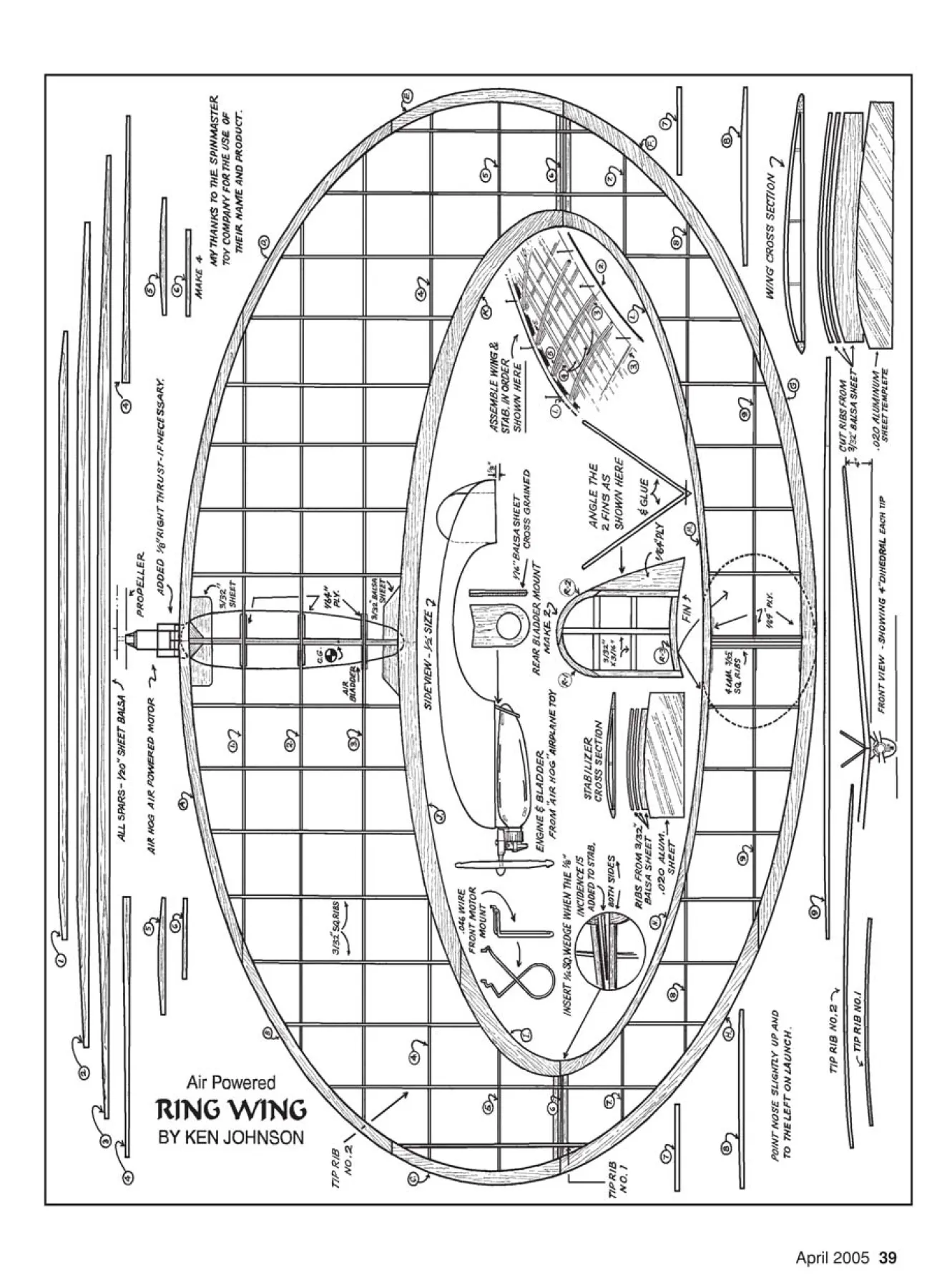
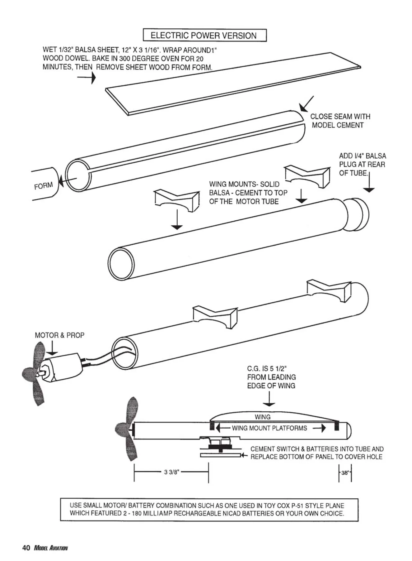

