
with radio reception. They can also be
dangerous if they come into contact with an
electrical charge from the receiver battery.
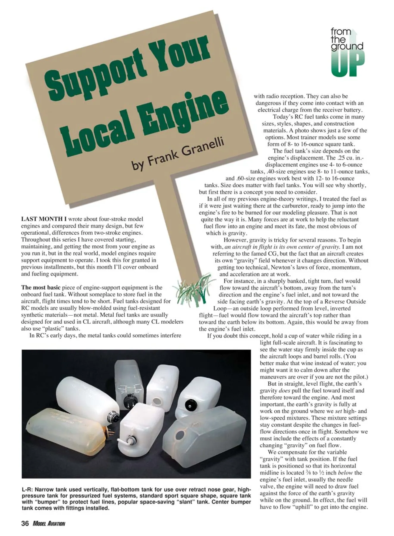
Today’s RC fuel tanks come in many
sizes, styles, shapes, and construction
materials. A photo shows just a few of the
options. Most trainer models use some
form of 8- to 16-ounce square tank.
The fuel tank’s size depends on the
engine’s displacement. The .25 cu. in.-
displacement engines use 4- to 6-ounce
tanks, .40-size engines use 8- to 11-ounce tanks,
and .60-size engines work best with 12- to 16-ounce
tanks. Size does matter with fuel tanks. You will see why shortly,
but first there is a concept you need to consider.
In all of my previous engine-theory writings, I treated the fuel as
if it were just waiting there at the carburetor, ready to jump into the
engine’s fire to be burned for our modeling pleasure. That is not
quite the way it is. Many forces are at work to help the reluctant
fuel flow into an engine and meet its fate, the most obvious of
which is gravity.
However, gravity is tricky for several reasons. To begin
with, an aircraft in flight is its own center of gravity. I am not
referring to the famed CG, but the fact that an aircraft creates
its own “gravity” field whenever it changes direction. Without
getting too technical, Newton’s laws of force, momentum,
and acceleration are at work.
For instance, in a sharply banked, tight turn, fuel would
flow toward the aircraft’s bottom, away from the turn’s
direction and the engine’s fuel inlet, and not toward the
side facing earth’s gravity. At the top of a Reverse Outside
Loop—an outside loop performed from level, inverted
flight—fuel would flow toward the aircraft’s top rather than
toward the earth below its bottom. Again, this would be away from
the engine’s fuel inlet.
If you doubt this concept, hold a cup of water while riding in a
light full-scale aircraft. It is fascinating to
see the water stay firmly inside the cup as
the aircraft loops and barrel rolls. (You
better make that wine instead of water; you
might want it to calm down after the
maneuvers are over if you are not the pilot.)
But in straight, level flight, the earth’s
gravity does pull the fuel toward itself and
therefore toward the engine. And most
important, the earth’s gravity is fully at
work on the ground where we set high- and
low-speed mixtures. These mixture settings
stay constant despite the changes in fuelflow
directions once in flight. Somehow we
must include the effects of a constantly
changing “gravity” on fuel flow.
We compensate for the variable
“gravity” with tank position. If the fuel
tank is positioned so that its horizontal
midline is located 3⁄8 to 1⁄2 inch below the
engine’s fuel inlet, usually the needle
valve, the engine will need to draw fuel
against the force of the earth’s gravity
while on the ground. In effect, the fuel will
have to flow “uphill” to get into the engine.
LAST MONTH I wrote about four-stroke model
engines and compared their many design, but few
operational, differences from two-stroke engines.
Throughout this series I have covered starting,
maintaining, and getting the most from your engine as
you run it, but in the real world, model engines require
support equipment to operate. I took this for granted in
previous installments, but this month I’ll cover onboard
and fueling equipment.
The most basic piece of engine-support equipment is the
onboard fuel tank. Without someplace to store fuel in the
aircraft, flight times tend to be short. Fuel tanks designed for
RC models are usually blow-molded using fuel-resistant
synthetic materials—not metal. Metal fuel tanks are usually
designed for and used in CL aircraft, although many CL modelers
also use “plastic” tanks.
In RC’s early days, the metal tanks could sometimes interfere
L-R: Narrow tank used vertically, flat-bottom tank for use over retract nose gear, highpressure
tank for pressurized fuel systems, standard sport square shape, square tank
with “bumper” to protect fuel lines, popular space-saving “slant” tank. Center bumper
tank comes with fittings installed.
Once in flight, many common maneuvers can only serve to
“richen” the mixture. In level, inverted flight or rolls, the earth’s
gravity tends to pull the fuel “downhill” into the engine, resulting in
a slightly richer mixture. When the aircraft’s motion pulls fuel away
from the inlet, as in the tight turns and outside loops mentioned
previously, the “mixture leaning” effect is reduced since the engine
has already been set to pull fuel “uphill.”
A photo shows the best tank position in relation to the engine’s
needle valve. Tank distance from the engine is also critical. For .25-
.65 engines without fuel pumps—most trainer engines—the fuel
tank should be a maximum of 4-5 inches behind the engine. The
closer, the better. Remember that the engine must draw the fuel over
this distance as well as fight gravity.
Why can’t we just put a 16-ounce tank behind a .25 cu. in. engine
and fly for an hour? Because of something called “head pressure,”
which is the second force pushing fuel into the engine.
The weight of the fuel itself is acting to push it through the small
opening, into the engine. The larger the tank size, the heavier the
fuel is and the greater the force pushing it out of the tank. In the .25-
engine scenario, the needle valves would have to be set extremely
“lean” to compensate for the full tank’s high head pressure.
But as the tank empties during flight, the head pressure drops.
Approximately halfway into the flight, the pressure gets so low that
the mixture settings, made with a full tank, are too lean. The engine
November 2004 37
Photos by the author except as noted
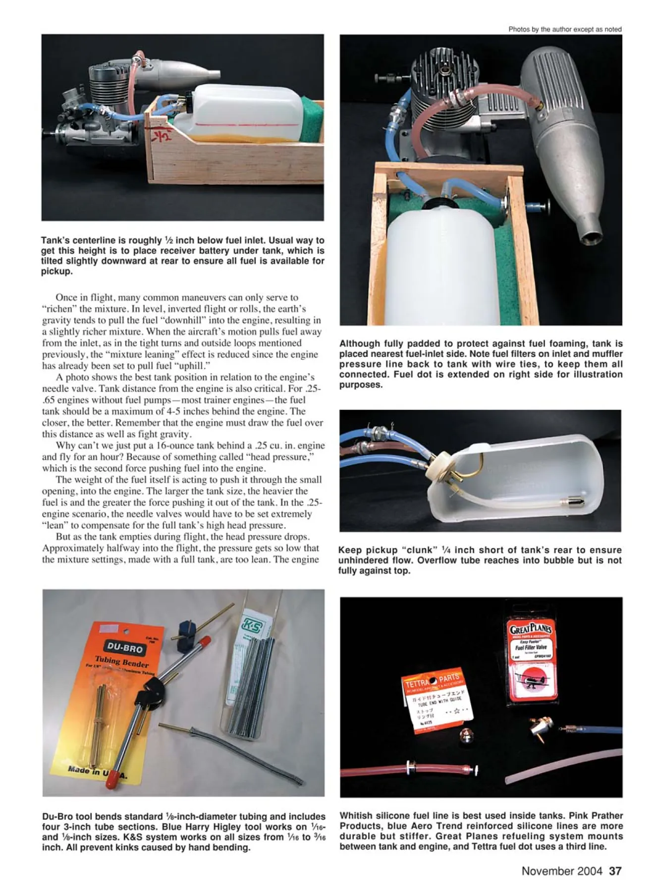
Tank’s centerline is roughly 1⁄2 inch below fuel inlet. Usual way to
get this height is to place receiver battery under tank, which is
tilted slightly downward at rear to ensure all fuel is available for
pickup.
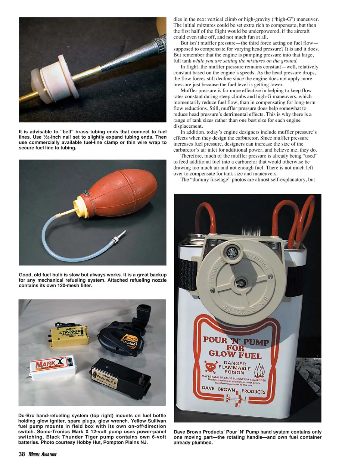
Although fully padded to protect against fuel foaming, tank is
placed nearest fuel-inlet side. Note fuel filters on inlet and muffler
pressure line back to tank with wire ties, to keep them all
connected. Fuel dot is extended on right side for illustration
purposes.
Keep pickup “clunk” 1⁄4 inch short of tank’s rear to ensure
unhindered flow. Overflow tube reaches into bubble but is not
fully against top.
Du-Bro tool bends standard 1⁄8-inch-diameter tubing and includes
four 3-inch tube sections. Blue Harry Higley tool works on 1⁄16-
and 1⁄8-inch sizes. K&S system works on all sizes from 1⁄16 to 3⁄16
inch. All prevent kinks caused by hand bending.
Whitish silicone fuel line is best used inside tanks. Pink Prather
Products, blue Aero Trend reinforced silicone lines are more
durable but stiffer. Great Planes refueling system mounts
between tank and engine, and Tettra fuel dot uses a third line.
dies in the next vertical climb or high-gravity (“high-G”) maneuver.
The initial mixtures could be set extra rich to compensate, but then
the first half of the flight would be underpowered, if the aircraft
could even take off, and not much fun at all.
But isn’t muffler pressure—the third force acting on fuel flow—
supposed to compensate for varying head pressure? It is and it does.
But remember that the engine is pumping pressure into that large,
full tank while you are setting the mixtures on the ground.
In flight, the muffler pressure remains constant—well, relatively
constant based on the engine’s speeds. As the head pressure drops,
the flow forces still decline since the engine does not apply more
pressure just because the fuel level is getting lower.
Muffler pressure is far more effective in helping to keep flow
rates constant during steep climbs and high-G maneuvers, which
momentarily reduce fuel flow, than in compensating for long-term
flow reductions. Still, muffler pressure does help somewhat to
reduce head pressure’s detrimental effects. This is why there is a
range of tank sizes rather than one best size for each engine
displacement.
In addition, today’s engine designers include muffler pressure’s
effects when they design the carburetor. Since muffler pressure
increases fuel pressure, designers can increase the size of the
carburetor’s air inlet for additional power, and believe me, they do.
Therefore, much of the muffler pressure is already being “used”
to feed additional fuel into a carburetor that would otherwise be
drawing too much air and not enough fuel. There is not much left
over to compensate for tank size and maneuvers.
The “dummy fuselage” photos are almost self-explanatory, but
38 MODEL AVIATION
It is advisable to “bell” brass tubing ends that connect to fuel
lines. Use 1⁄32-inch nail set to slightly expand tubing ends. Then
use commercially available fuel-line clamp or thin wire wrap to
secure fuel line to tubing.
Good, old fuel bulb is slow but always works. It is a great backup
for any mechanical refueling system. Attached refueling nozzle
contains its own 120-mesh filter.
Du-Bro hand-refueling system (top right) mounts on fuel bottle
holding glow igniter, spare plugs, glow wrench. Yellow Sullivan
fuel pump mounts in field box with its own on-off/direction
switch. Sonic-Tronics Mark X 12-volt pump uses power-panel
switching. Black Thunder Tiger pump contains own 6-volt
batteries. Photo courtesy Hobby Hut, Pompton Plains NJ.
Dave Brown Products’ Pour ‘N’ Pump hand system contains only
one moving part—the rotating handle—and own fuel container
already plumbed.
some parts are worth mentioning. Notice
that the tank’s fuel-outlet line is roughly the
same height as the engine’s fuel inlet. Try to
run the fuel line directly to the inlet, without
going far downhill, and then way back up.
If there is too much “uphill,” the engine
could quit lean as fuel levels reach the last
few ounces and head pressure vanishes. If
your engine always quits before the tank is
empty, check for this roller-coaster
condition.
Also note that the fuel tank is not
centered behind the engine. The tank’s fuel
outlet is positioned slightly more toward the
side with the needle valve. This reduces the
uphill/downhill effect no matter which
direction the aircraft banks or rolls. Fuel
flow remains almost constant. If possible,
mount the tank inside a thin foam layer to
reduce possible “bubbling” from the
engine’s vibration, as shown.
If the engine is tightly cowled, or the
fuel line to the engine cannot easily be
disconnected for refueling, you will need a
third line to the fuel tank. This “fill line”
must be blocked off after filling to prevent
muffler-pressure loss during operation. The
photo shows a “fuel dot” used for this
purpose, which is simple and popular. Little
can go wrong unless you somehow lose the
dot while refueling.
Other popular methods exist, such as the
Great Planes Fuel Filler Valve, that block
the fuel flow into the engine while filling
the tank, to prevent accidental engine
flooding. However, sometimes such
systems require longer fuel-line runs to the
engine. It is often a good idea in such cases
to use a third line anyway.
The filler valve connects to the tank, as
would a fuel dot, allowing the engine’s fuel
line to be made as short and direct as
possible. Block off the unused port with a
short piece of fuel line capped with a small
4-40 bolt. There are so many onboard
refueling systems available that you should
check your local hobby shop to find the
ones that seem best to you.
Hooking the lines up inside the tank is
also fairly simple. The cutaway photo
shows how to position a three-line system
inside the tank. If the tank has a bubble
section, position the muffler pressure/
overflow brass tubing inside the bubble for
maximum tank capacity. Most fuel tanks
include enough brass tubing to fabricate any
three-line system.
Try to reach into the bubble with as
straight a brass tubing “run” as possible.
This helps prevent the fuel “pickup” line
from wrapping itself around the vent
tubing and getting stuck in a full forward
position, which could cause the engine to
quit during the next vertical maneuver.
Some modelers prefer to use rigid
plastic tubing on the pickup line to
prevent this, but sometimes that also
prevents the engine from receiving fuel
during long vertical dives or spins. That is
a modeler’s choice, however.
To further reduce the chance of pickupline
fouling, the fuel-inlet tubing (the fill
line) should be a straight line into the tank,
as shown. Most fuel pumps have no trouble
filling the tank against any extra pressure
this may cause. Squeeze the filling line
while installing the fuel-dot cap or quickly
close whatever fueling system you are using
to prevent spilling fuel once the pump line
is removed.
Bending the brass tubing is fairly easy,
but you must be careful to avoid kinking it
if you bend it by hand. Several great tubing
benders, shown, prevent kinks while
providing just the angles needed. There are
many others, so get the one you prefer.
If you accidentally bend the tubing,
carefully apply pressure on the sides of the
spot using pliers. This makes the tubing
round enough to allow operation if you do
not have a spare brass tube (available in
most hobby shops).
Some flexible tubing—called fuel
line—is also required to connect the
tank’s brass tubing to the engine, muffler,
and fill port. At one time there were many
types of fuel line available, but only two
are commonly used today.
Pure silicone fuel line is used inside
the tank. This semiclear tubing is
extremely flexible and allows the pickup
line to conform to the aircraft’s
maneuvers without kinking or leaving the
fuel itself. It is also fuelproof and is
unaffected by model fuel. It lasts almost
forever without stiffening or degrading.
On the other hand, pure silicone fuel line
is prone to cracking or rubbing wear. It
also tends to slip off the brass tubing if it’s
improperly secured. It is great inside the
tank but does not last long outside of it.
Therefore, a form of “reinforced” silicone
fuel line has become popular.
As is pure silicone, reinforced silicone
is totally fuelproof. Unlike pure silicone, it
is resistant to cracking and vibration wear
and tends to stay connected. Fuel lines,
which were once problematic, are now
nearly trouble-free for years. Just make
sure there is no firm contact between the
fuel line and the fuselage structure, to
prevent wear caused by vibration.
What about the fuel line’s size, or
diameter? This is not as critical as it once
was since engine-fuel draw has greatly
improved. Consider it, but don’t lose too
much sleep over it. Small-diameter fuel
line is good for up to .25 cu. in. engines.
Larger engines, up to .65 cu. in., require
medium-diameter fuel line. Engines larger
than .65 cu. in. work well with largediameter
line.
The best way to know for sure what
size to use is to compare the engine’s inlet
diameter (inside measurement) at the highspeed
needle valve to the inside fuel-line
diameter. Try to match these diameters as
closely as possible.
A slightly larger-diameter fuel line is
preferable to a smaller size if a perfect
match is impossible. Just make sure that
the fuel line has a firm grip on the
engine’s fuel inlet and will not slip off.
In emergencies, I have used mediumdiameter
fuel line on 1.40 cu. in. engines
without noticeable differences, so fuelline
diameter may not be extremely
important.
The last part of tank installation is the
fuel filter, but this is not open to debate.
Reality trumps anyone’s opinion; use a
good filter or have problems. It is that
simple. Competition fliers have proven
this many times throughout many years. I
relearn this lesson every 200 or so flights
on my competition aircraft.
Despite triple-filtering the fuel during
refueling, from a 100-mesh screen down
to a 250-mesh screen, I must clean the
onboard fuel filters in my competition
aircraft every 200 flights or they start to
clog. Alcohol-insoluble material builds up
inside the filters and must be removed
using paint thinner. If the filters didn’t
catch this material, it would eventually
clog small carburetor sections or fuelpump
parts. Nothing but grief comes of
this.
It is also a good idea to install a second
filter in the muffler pressure line, between
the muffler and the fuel tank. This limits
the amount of junk the engine blows back
into the fuel tank.
The only caveat about using filters is to
make sure their sections are tight to prevent
air leaks. Clean the filters every 200-300
flights for non-pumped engines or every
200 flights for pump-equipped engines.
The onboard fuel tank is perfectly sized,
constructed, plumbed, and positioned; now
we can go flying—except the fuel tank is
still empty. We can’t do more than testglide
the airplane without fuel, so how do
we get it into the aircraft’s tank?
For several years, my early refueling
system was a 2-ounce turkey baster with a
fuel tube attached. It was slow, but it
worked! Such systems are still available,
but in larger sizes, as shown. These
squeeze bulbs are convenient backups if
the primary refueling system fails at the
field. You may want to include one in
your field box just in case.
But more sophisticated refueling
methods are the most popular by far. As
shown, there are four popular types. There
are various kinds of hand pumps, some of
which fit on the plastic fuel jug and use a
hand-crank pump. Rotate the handle one
direction and the fuel flows into the
aircraft. Rotate the other way and out it
comes after the flying day is done.
Some, such as the Du-Bro system
shown, also hold the glow-plug igniter and
spare parts. Others, such as Dave Brown
Products’ Pump-N-Go system, may
include the fuel container as well.
There are refueling systems that attach
directly to the fuel container and resemble
the hand systems but use electric pumps.
They usually also contain batteries for
power. Field-box fuel pumps may also
contain their own batteries, but most use
the 12-volt field-box battery.
Some systems, such as the yellow
Sullivan fuel pump in the picture, have
their own on-off/directional switches, and
others use the fuel-pump switch on the
field box’s power panel (more about that
next month), as the Mark X electric fuel
pump does.
The fuel line used to plumb the
refueling system is usually the same
reinforced silicone line used onboard the
aircraft. Many electric-fuel-pump
manufacturers recommend that the large
fuel line be used to reduce wear on the
pump. Sometimes that requires using a
short length of medium fuel line over the
filling nozzle and then applying the large
line over the assembly.
The refueling system has fuel filters; be
sure to clean them more often than you
clean the onboard filters. Refueling filters
may be used for more than one aircraft, so
they require more frequent service.
Now that the aircraft is fueled and ready to
go, we need to turn it over and light the glow
plug to get it started. We also need to hold it
in place safely during run-up and settings.
Next month, which will be the last
installment of the engine segment, I will
cover field boxes, batteries, starters, glowplug
igniters, and chicken sticks. MA
Frank Granelli
24 Old Middletown Rd.
Rockaway NJ 07866
Edition: Model Aviation - 2004/11
Page Numbers: 36,37,38,40,43
Edition: Model Aviation - 2004/11
Page Numbers: 36,37,38,40,43
with radio reception. They can also be
dangerous if they come into contact with an
electrical charge from the receiver battery.
Today’s RC fuel tanks come in many
sizes, styles, shapes, and construction
materials. A photo shows just a few of the
options. Most trainer models use some
form of 8- to 16-ounce square tank.
The fuel tank’s size depends on the
engine’s displacement. The .25 cu. in.-
displacement engines use 4- to 6-ounce
tanks, .40-size engines use 8- to 11-ounce tanks,
and .60-size engines work best with 12- to 16-ounce
tanks. Size does matter with fuel tanks. You will see why shortly,
but first there is a concept you need to consider.
In all of my previous engine-theory writings, I treated the fuel as
if it were just waiting there at the carburetor, ready to jump into the
engine’s fire to be burned for our modeling pleasure. That is not
quite the way it is. Many forces are at work to help the reluctant
fuel flow into an engine and meet its fate, the most obvious of
which is gravity.
However, gravity is tricky for several reasons. To begin
with, an aircraft in flight is its own center of gravity. I am not
referring to the famed CG, but the fact that an aircraft creates
its own “gravity” field whenever it changes direction. Without
getting too technical, Newton’s laws of force, momentum,
and acceleration are at work.
For instance, in a sharply banked, tight turn, fuel would
flow toward the aircraft’s bottom, away from the turn’s
direction and the engine’s fuel inlet, and not toward the
side facing earth’s gravity. At the top of a Reverse Outside
Loop—an outside loop performed from level, inverted
flight—fuel would flow toward the aircraft’s top rather than
toward the earth below its bottom. Again, this would be away from
the engine’s fuel inlet.
If you doubt this concept, hold a cup of water while riding in a
light full-scale aircraft. It is fascinating to
see the water stay firmly inside the cup as
the aircraft loops and barrel rolls. (You
better make that wine instead of water; you
might want it to calm down after the
maneuvers are over if you are not the pilot.)
But in straight, level flight, the earth’s
gravity does pull the fuel toward itself and
therefore toward the engine. And most
important, the earth’s gravity is fully at
work on the ground where we set high- and
low-speed mixtures. These mixture settings
stay constant despite the changes in fuelflow
directions once in flight. Somehow we
must include the effects of a constantly
changing “gravity” on fuel flow.
We compensate for the variable
“gravity” with tank position. If the fuel
tank is positioned so that its horizontal
midline is located 3⁄8 to 1⁄2 inch below the
engine’s fuel inlet, usually the needle
valve, the engine will need to draw fuel
against the force of the earth’s gravity
while on the ground. In effect, the fuel will
have to flow “uphill” to get into the engine.
LAST MONTH I wrote about four-stroke model
engines and compared their many design, but few
operational, differences from two-stroke engines.
Throughout this series I have covered starting,
maintaining, and getting the most from your engine as
you run it, but in the real world, model engines require
support equipment to operate. I took this for granted in
previous installments, but this month I’ll cover onboard
and fueling equipment.
The most basic piece of engine-support equipment is the
onboard fuel tank. Without someplace to store fuel in the
aircraft, flight times tend to be short. Fuel tanks designed for
RC models are usually blow-molded using fuel-resistant
synthetic materials—not metal. Metal fuel tanks are usually
designed for and used in CL aircraft, although many CL modelers
also use “plastic” tanks.
In RC’s early days, the metal tanks could sometimes interfere
L-R: Narrow tank used vertically, flat-bottom tank for use over retract nose gear, highpressure
tank for pressurized fuel systems, standard sport square shape, square tank
with “bumper” to protect fuel lines, popular space-saving “slant” tank. Center bumper
tank comes with fittings installed.
Once in flight, many common maneuvers can only serve to
“richen” the mixture. In level, inverted flight or rolls, the earth’s
gravity tends to pull the fuel “downhill” into the engine, resulting in
a slightly richer mixture. When the aircraft’s motion pulls fuel away
from the inlet, as in the tight turns and outside loops mentioned
previously, the “mixture leaning” effect is reduced since the engine
has already been set to pull fuel “uphill.”
A photo shows the best tank position in relation to the engine’s
needle valve. Tank distance from the engine is also critical. For .25-
.65 engines without fuel pumps—most trainer engines—the fuel
tank should be a maximum of 4-5 inches behind the engine. The
closer, the better. Remember that the engine must draw the fuel over
this distance as well as fight gravity.
Why can’t we just put a 16-ounce tank behind a .25 cu. in. engine
and fly for an hour? Because of something called “head pressure,”
which is the second force pushing fuel into the engine.
The weight of the fuel itself is acting to push it through the small
opening, into the engine. The larger the tank size, the heavier the
fuel is and the greater the force pushing it out of the tank. In the .25-
engine scenario, the needle valves would have to be set extremely
“lean” to compensate for the full tank’s high head pressure.
But as the tank empties during flight, the head pressure drops.
Approximately halfway into the flight, the pressure gets so low that
the mixture settings, made with a full tank, are too lean. The engine
November 2004 37
Photos by the author except as noted
Tank’s centerline is roughly 1⁄2 inch below fuel inlet. Usual way to
get this height is to place receiver battery under tank, which is
tilted slightly downward at rear to ensure all fuel is available for
pickup.
Although fully padded to protect against fuel foaming, tank is
placed nearest fuel-inlet side. Note fuel filters on inlet and muffler
pressure line back to tank with wire ties, to keep them all
connected. Fuel dot is extended on right side for illustration
purposes.
Keep pickup “clunk” 1⁄4 inch short of tank’s rear to ensure
unhindered flow. Overflow tube reaches into bubble but is not
fully against top.
Du-Bro tool bends standard 1⁄8-inch-diameter tubing and includes
four 3-inch tube sections. Blue Harry Higley tool works on 1⁄16-
and 1⁄8-inch sizes. K&S system works on all sizes from 1⁄16 to 3⁄16
inch. All prevent kinks caused by hand bending.
Whitish silicone fuel line is best used inside tanks. Pink Prather
Products, blue Aero Trend reinforced silicone lines are more
durable but stiffer. Great Planes refueling system mounts
between tank and engine, and Tettra fuel dot uses a third line.
dies in the next vertical climb or high-gravity (“high-G”) maneuver.
The initial mixtures could be set extra rich to compensate, but then
the first half of the flight would be underpowered, if the aircraft
could even take off, and not much fun at all.
But isn’t muffler pressure—the third force acting on fuel flow—
supposed to compensate for varying head pressure? It is and it does.
But remember that the engine is pumping pressure into that large,
full tank while you are setting the mixtures on the ground.
In flight, the muffler pressure remains constant—well, relatively
constant based on the engine’s speeds. As the head pressure drops,
the flow forces still decline since the engine does not apply more
pressure just because the fuel level is getting lower.
Muffler pressure is far more effective in helping to keep flow
rates constant during steep climbs and high-G maneuvers, which
momentarily reduce fuel flow, than in compensating for long-term
flow reductions. Still, muffler pressure does help somewhat to
reduce head pressure’s detrimental effects. This is why there is a
range of tank sizes rather than one best size for each engine
displacement.
In addition, today’s engine designers include muffler pressure’s
effects when they design the carburetor. Since muffler pressure
increases fuel pressure, designers can increase the size of the
carburetor’s air inlet for additional power, and believe me, they do.
Therefore, much of the muffler pressure is already being “used”
to feed additional fuel into a carburetor that would otherwise be
drawing too much air and not enough fuel. There is not much left
over to compensate for tank size and maneuvers.
The “dummy fuselage” photos are almost self-explanatory, but
38 MODEL AVIATION
It is advisable to “bell” brass tubing ends that connect to fuel
lines. Use 1⁄32-inch nail set to slightly expand tubing ends. Then
use commercially available fuel-line clamp or thin wire wrap to
secure fuel line to tubing.
Good, old fuel bulb is slow but always works. It is a great backup
for any mechanical refueling system. Attached refueling nozzle
contains its own 120-mesh filter.
Du-Bro hand-refueling system (top right) mounts on fuel bottle
holding glow igniter, spare plugs, glow wrench. Yellow Sullivan
fuel pump mounts in field box with its own on-off/direction
switch. Sonic-Tronics Mark X 12-volt pump uses power-panel
switching. Black Thunder Tiger pump contains own 6-volt
batteries. Photo courtesy Hobby Hut, Pompton Plains NJ.
Dave Brown Products’ Pour ‘N’ Pump hand system contains only
one moving part—the rotating handle—and own fuel container
already plumbed.
some parts are worth mentioning. Notice
that the tank’s fuel-outlet line is roughly the
same height as the engine’s fuel inlet. Try to
run the fuel line directly to the inlet, without
going far downhill, and then way back up.
If there is too much “uphill,” the engine
could quit lean as fuel levels reach the last
few ounces and head pressure vanishes. If
your engine always quits before the tank is
empty, check for this roller-coaster
condition.
Also note that the fuel tank is not
centered behind the engine. The tank’s fuel
outlet is positioned slightly more toward the
side with the needle valve. This reduces the
uphill/downhill effect no matter which
direction the aircraft banks or rolls. Fuel
flow remains almost constant. If possible,
mount the tank inside a thin foam layer to
reduce possible “bubbling” from the
engine’s vibration, as shown.
If the engine is tightly cowled, or the
fuel line to the engine cannot easily be
disconnected for refueling, you will need a
third line to the fuel tank. This “fill line”
must be blocked off after filling to prevent
muffler-pressure loss during operation. The
photo shows a “fuel dot” used for this
purpose, which is simple and popular. Little
can go wrong unless you somehow lose the
dot while refueling.
Other popular methods exist, such as the
Great Planes Fuel Filler Valve, that block
the fuel flow into the engine while filling
the tank, to prevent accidental engine
flooding. However, sometimes such
systems require longer fuel-line runs to the
engine. It is often a good idea in such cases
to use a third line anyway.
The filler valve connects to the tank, as
would a fuel dot, allowing the engine’s fuel
line to be made as short and direct as
possible. Block off the unused port with a
short piece of fuel line capped with a small
4-40 bolt. There are so many onboard
refueling systems available that you should
check your local hobby shop to find the
ones that seem best to you.
Hooking the lines up inside the tank is
also fairly simple. The cutaway photo
shows how to position a three-line system
inside the tank. If the tank has a bubble
section, position the muffler pressure/
overflow brass tubing inside the bubble for
maximum tank capacity. Most fuel tanks
include enough brass tubing to fabricate any
three-line system.
Try to reach into the bubble with as
straight a brass tubing “run” as possible.
This helps prevent the fuel “pickup” line
from wrapping itself around the vent
tubing and getting stuck in a full forward
position, which could cause the engine to
quit during the next vertical maneuver.
Some modelers prefer to use rigid
plastic tubing on the pickup line to
prevent this, but sometimes that also
prevents the engine from receiving fuel
during long vertical dives or spins. That is
a modeler’s choice, however.
To further reduce the chance of pickupline
fouling, the fuel-inlet tubing (the fill
line) should be a straight line into the tank,
as shown. Most fuel pumps have no trouble
filling the tank against any extra pressure
this may cause. Squeeze the filling line
while installing the fuel-dot cap or quickly
close whatever fueling system you are using
to prevent spilling fuel once the pump line
is removed.
Bending the brass tubing is fairly easy,
but you must be careful to avoid kinking it
if you bend it by hand. Several great tubing
benders, shown, prevent kinks while
providing just the angles needed. There are
many others, so get the one you prefer.
If you accidentally bend the tubing,
carefully apply pressure on the sides of the
spot using pliers. This makes the tubing
round enough to allow operation if you do
not have a spare brass tube (available in
most hobby shops).
Some flexible tubing—called fuel
line—is also required to connect the
tank’s brass tubing to the engine, muffler,
and fill port. At one time there were many
types of fuel line available, but only two
are commonly used today.
Pure silicone fuel line is used inside
the tank. This semiclear tubing is
extremely flexible and allows the pickup
line to conform to the aircraft’s
maneuvers without kinking or leaving the
fuel itself. It is also fuelproof and is
unaffected by model fuel. It lasts almost
forever without stiffening or degrading.
On the other hand, pure silicone fuel line
is prone to cracking or rubbing wear. It
also tends to slip off the brass tubing if it’s
improperly secured. It is great inside the
tank but does not last long outside of it.
Therefore, a form of “reinforced” silicone
fuel line has become popular.
As is pure silicone, reinforced silicone
is totally fuelproof. Unlike pure silicone, it
is resistant to cracking and vibration wear
and tends to stay connected. Fuel lines,
which were once problematic, are now
nearly trouble-free for years. Just make
sure there is no firm contact between the
fuel line and the fuselage structure, to
prevent wear caused by vibration.
What about the fuel line’s size, or
diameter? This is not as critical as it once
was since engine-fuel draw has greatly
improved. Consider it, but don’t lose too
much sleep over it. Small-diameter fuel
line is good for up to .25 cu. in. engines.
Larger engines, up to .65 cu. in., require
medium-diameter fuel line. Engines larger
than .65 cu. in. work well with largediameter
line.
The best way to know for sure what
size to use is to compare the engine’s inlet
diameter (inside measurement) at the highspeed
needle valve to the inside fuel-line
diameter. Try to match these diameters as
closely as possible.
A slightly larger-diameter fuel line is
preferable to a smaller size if a perfect
match is impossible. Just make sure that
the fuel line has a firm grip on the
engine’s fuel inlet and will not slip off.
In emergencies, I have used mediumdiameter
fuel line on 1.40 cu. in. engines
without noticeable differences, so fuelline
diameter may not be extremely
important.
The last part of tank installation is the
fuel filter, but this is not open to debate.
Reality trumps anyone’s opinion; use a
good filter or have problems. It is that
simple. Competition fliers have proven
this many times throughout many years. I
relearn this lesson every 200 or so flights
on my competition aircraft.
Despite triple-filtering the fuel during
refueling, from a 100-mesh screen down
to a 250-mesh screen, I must clean the
onboard fuel filters in my competition
aircraft every 200 flights or they start to
clog. Alcohol-insoluble material builds up
inside the filters and must be removed
using paint thinner. If the filters didn’t
catch this material, it would eventually
clog small carburetor sections or fuelpump
parts. Nothing but grief comes of
this.
It is also a good idea to install a second
filter in the muffler pressure line, between
the muffler and the fuel tank. This limits
the amount of junk the engine blows back
into the fuel tank.
The only caveat about using filters is to
make sure their sections are tight to prevent
air leaks. Clean the filters every 200-300
flights for non-pumped engines or every
200 flights for pump-equipped engines.
The onboard fuel tank is perfectly sized,
constructed, plumbed, and positioned; now
we can go flying—except the fuel tank is
still empty. We can’t do more than testglide
the airplane without fuel, so how do
we get it into the aircraft’s tank?
For several years, my early refueling
system was a 2-ounce turkey baster with a
fuel tube attached. It was slow, but it
worked! Such systems are still available,
but in larger sizes, as shown. These
squeeze bulbs are convenient backups if
the primary refueling system fails at the
field. You may want to include one in
your field box just in case.
But more sophisticated refueling
methods are the most popular by far. As
shown, there are four popular types. There
are various kinds of hand pumps, some of
which fit on the plastic fuel jug and use a
hand-crank pump. Rotate the handle one
direction and the fuel flows into the
aircraft. Rotate the other way and out it
comes after the flying day is done.
Some, such as the Du-Bro system
shown, also hold the glow-plug igniter and
spare parts. Others, such as Dave Brown
Products’ Pump-N-Go system, may
include the fuel container as well.
There are refueling systems that attach
directly to the fuel container and resemble
the hand systems but use electric pumps.
They usually also contain batteries for
power. Field-box fuel pumps may also
contain their own batteries, but most use
the 12-volt field-box battery.
Some systems, such as the yellow
Sullivan fuel pump in the picture, have
their own on-off/directional switches, and
others use the fuel-pump switch on the
field box’s power panel (more about that
next month), as the Mark X electric fuel
pump does.
The fuel line used to plumb the
refueling system is usually the same
reinforced silicone line used onboard the
aircraft. Many electric-fuel-pump
manufacturers recommend that the large
fuel line be used to reduce wear on the
pump. Sometimes that requires using a
short length of medium fuel line over the
filling nozzle and then applying the large
line over the assembly.
The refueling system has fuel filters; be
sure to clean them more often than you
clean the onboard filters. Refueling filters
may be used for more than one aircraft, so
they require more frequent service.
Now that the aircraft is fueled and ready to
go, we need to turn it over and light the glow
plug to get it started. We also need to hold it
in place safely during run-up and settings.
Next month, which will be the last
installment of the engine segment, I will
cover field boxes, batteries, starters, glowplug
igniters, and chicken sticks. MA
Frank Granelli
24 Old Middletown Rd.
Rockaway NJ 07866
Edition: Model Aviation - 2004/11
Page Numbers: 36,37,38,40,43
with radio reception. They can also be
dangerous if they come into contact with an
electrical charge from the receiver battery.
Today’s RC fuel tanks come in many
sizes, styles, shapes, and construction
materials. A photo shows just a few of the
options. Most trainer models use some
form of 8- to 16-ounce square tank.
The fuel tank’s size depends on the
engine’s displacement. The .25 cu. in.-
displacement engines use 4- to 6-ounce
tanks, .40-size engines use 8- to 11-ounce tanks,
and .60-size engines work best with 12- to 16-ounce
tanks. Size does matter with fuel tanks. You will see why shortly,
but first there is a concept you need to consider.
In all of my previous engine-theory writings, I treated the fuel as
if it were just waiting there at the carburetor, ready to jump into the
engine’s fire to be burned for our modeling pleasure. That is not
quite the way it is. Many forces are at work to help the reluctant
fuel flow into an engine and meet its fate, the most obvious of
which is gravity.
However, gravity is tricky for several reasons. To begin
with, an aircraft in flight is its own center of gravity. I am not
referring to the famed CG, but the fact that an aircraft creates
its own “gravity” field whenever it changes direction. Without
getting too technical, Newton’s laws of force, momentum,
and acceleration are at work.
For instance, in a sharply banked, tight turn, fuel would
flow toward the aircraft’s bottom, away from the turn’s
direction and the engine’s fuel inlet, and not toward the
side facing earth’s gravity. At the top of a Reverse Outside
Loop—an outside loop performed from level, inverted
flight—fuel would flow toward the aircraft’s top rather than
toward the earth below its bottom. Again, this would be away from
the engine’s fuel inlet.
If you doubt this concept, hold a cup of water while riding in a
light full-scale aircraft. It is fascinating to
see the water stay firmly inside the cup as
the aircraft loops and barrel rolls. (You
better make that wine instead of water; you
might want it to calm down after the
maneuvers are over if you are not the pilot.)
But in straight, level flight, the earth’s
gravity does pull the fuel toward itself and
therefore toward the engine. And most
important, the earth’s gravity is fully at
work on the ground where we set high- and
low-speed mixtures. These mixture settings
stay constant despite the changes in fuelflow
directions once in flight. Somehow we
must include the effects of a constantly
changing “gravity” on fuel flow.
We compensate for the variable
“gravity” with tank position. If the fuel
tank is positioned so that its horizontal
midline is located 3⁄8 to 1⁄2 inch below the
engine’s fuel inlet, usually the needle
valve, the engine will need to draw fuel
against the force of the earth’s gravity
while on the ground. In effect, the fuel will
have to flow “uphill” to get into the engine.
LAST MONTH I wrote about four-stroke model
engines and compared their many design, but few
operational, differences from two-stroke engines.
Throughout this series I have covered starting,
maintaining, and getting the most from your engine as
you run it, but in the real world, model engines require
support equipment to operate. I took this for granted in
previous installments, but this month I’ll cover onboard
and fueling equipment.
The most basic piece of engine-support equipment is the
onboard fuel tank. Without someplace to store fuel in the
aircraft, flight times tend to be short. Fuel tanks designed for
RC models are usually blow-molded using fuel-resistant
synthetic materials—not metal. Metal fuel tanks are usually
designed for and used in CL aircraft, although many CL modelers
also use “plastic” tanks.
In RC’s early days, the metal tanks could sometimes interfere
L-R: Narrow tank used vertically, flat-bottom tank for use over retract nose gear, highpressure
tank for pressurized fuel systems, standard sport square shape, square tank
with “bumper” to protect fuel lines, popular space-saving “slant” tank. Center bumper
tank comes with fittings installed.
Once in flight, many common maneuvers can only serve to
“richen” the mixture. In level, inverted flight or rolls, the earth’s
gravity tends to pull the fuel “downhill” into the engine, resulting in
a slightly richer mixture. When the aircraft’s motion pulls fuel away
from the inlet, as in the tight turns and outside loops mentioned
previously, the “mixture leaning” effect is reduced since the engine
has already been set to pull fuel “uphill.”
A photo shows the best tank position in relation to the engine’s
needle valve. Tank distance from the engine is also critical. For .25-
.65 engines without fuel pumps—most trainer engines—the fuel
tank should be a maximum of 4-5 inches behind the engine. The
closer, the better. Remember that the engine must draw the fuel over
this distance as well as fight gravity.
Why can’t we just put a 16-ounce tank behind a .25 cu. in. engine
and fly for an hour? Because of something called “head pressure,”
which is the second force pushing fuel into the engine.
The weight of the fuel itself is acting to push it through the small
opening, into the engine. The larger the tank size, the heavier the
fuel is and the greater the force pushing it out of the tank. In the .25-
engine scenario, the needle valves would have to be set extremely
“lean” to compensate for the full tank’s high head pressure.
But as the tank empties during flight, the head pressure drops.
Approximately halfway into the flight, the pressure gets so low that
the mixture settings, made with a full tank, are too lean. The engine
November 2004 37
Photos by the author except as noted
Tank’s centerline is roughly 1⁄2 inch below fuel inlet. Usual way to
get this height is to place receiver battery under tank, which is
tilted slightly downward at rear to ensure all fuel is available for
pickup.
Although fully padded to protect against fuel foaming, tank is
placed nearest fuel-inlet side. Note fuel filters on inlet and muffler
pressure line back to tank with wire ties, to keep them all
connected. Fuel dot is extended on right side for illustration
purposes.
Keep pickup “clunk” 1⁄4 inch short of tank’s rear to ensure
unhindered flow. Overflow tube reaches into bubble but is not
fully against top.
Du-Bro tool bends standard 1⁄8-inch-diameter tubing and includes
four 3-inch tube sections. Blue Harry Higley tool works on 1⁄16-
and 1⁄8-inch sizes. K&S system works on all sizes from 1⁄16 to 3⁄16
inch. All prevent kinks caused by hand bending.
Whitish silicone fuel line is best used inside tanks. Pink Prather
Products, blue Aero Trend reinforced silicone lines are more
durable but stiffer. Great Planes refueling system mounts
between tank and engine, and Tettra fuel dot uses a third line.
dies in the next vertical climb or high-gravity (“high-G”) maneuver.
The initial mixtures could be set extra rich to compensate, but then
the first half of the flight would be underpowered, if the aircraft
could even take off, and not much fun at all.
But isn’t muffler pressure—the third force acting on fuel flow—
supposed to compensate for varying head pressure? It is and it does.
But remember that the engine is pumping pressure into that large,
full tank while you are setting the mixtures on the ground.
In flight, the muffler pressure remains constant—well, relatively
constant based on the engine’s speeds. As the head pressure drops,
the flow forces still decline since the engine does not apply more
pressure just because the fuel level is getting lower.
Muffler pressure is far more effective in helping to keep flow
rates constant during steep climbs and high-G maneuvers, which
momentarily reduce fuel flow, than in compensating for long-term
flow reductions. Still, muffler pressure does help somewhat to
reduce head pressure’s detrimental effects. This is why there is a
range of tank sizes rather than one best size for each engine
displacement.
In addition, today’s engine designers include muffler pressure’s
effects when they design the carburetor. Since muffler pressure
increases fuel pressure, designers can increase the size of the
carburetor’s air inlet for additional power, and believe me, they do.
Therefore, much of the muffler pressure is already being “used”
to feed additional fuel into a carburetor that would otherwise be
drawing too much air and not enough fuel. There is not much left
over to compensate for tank size and maneuvers.
The “dummy fuselage” photos are almost self-explanatory, but
38 MODEL AVIATION
It is advisable to “bell” brass tubing ends that connect to fuel
lines. Use 1⁄32-inch nail set to slightly expand tubing ends. Then
use commercially available fuel-line clamp or thin wire wrap to
secure fuel line to tubing.
Good, old fuel bulb is slow but always works. It is a great backup
for any mechanical refueling system. Attached refueling nozzle
contains its own 120-mesh filter.
Du-Bro hand-refueling system (top right) mounts on fuel bottle
holding glow igniter, spare plugs, glow wrench. Yellow Sullivan
fuel pump mounts in field box with its own on-off/direction
switch. Sonic-Tronics Mark X 12-volt pump uses power-panel
switching. Black Thunder Tiger pump contains own 6-volt
batteries. Photo courtesy Hobby Hut, Pompton Plains NJ.
Dave Brown Products’ Pour ‘N’ Pump hand system contains only
one moving part—the rotating handle—and own fuel container
already plumbed.
some parts are worth mentioning. Notice
that the tank’s fuel-outlet line is roughly the
same height as the engine’s fuel inlet. Try to
run the fuel line directly to the inlet, without
going far downhill, and then way back up.
If there is too much “uphill,” the engine
could quit lean as fuel levels reach the last
few ounces and head pressure vanishes. If
your engine always quits before the tank is
empty, check for this roller-coaster
condition.
Also note that the fuel tank is not
centered behind the engine. The tank’s fuel
outlet is positioned slightly more toward the
side with the needle valve. This reduces the
uphill/downhill effect no matter which
direction the aircraft banks or rolls. Fuel
flow remains almost constant. If possible,
mount the tank inside a thin foam layer to
reduce possible “bubbling” from the
engine’s vibration, as shown.
If the engine is tightly cowled, or the
fuel line to the engine cannot easily be
disconnected for refueling, you will need a
third line to the fuel tank. This “fill line”
must be blocked off after filling to prevent
muffler-pressure loss during operation. The
photo shows a “fuel dot” used for this
purpose, which is simple and popular. Little
can go wrong unless you somehow lose the
dot while refueling.
Other popular methods exist, such as the
Great Planes Fuel Filler Valve, that block
the fuel flow into the engine while filling
the tank, to prevent accidental engine
flooding. However, sometimes such
systems require longer fuel-line runs to the
engine. It is often a good idea in such cases
to use a third line anyway.
The filler valve connects to the tank, as
would a fuel dot, allowing the engine’s fuel
line to be made as short and direct as
possible. Block off the unused port with a
short piece of fuel line capped with a small
4-40 bolt. There are so many onboard
refueling systems available that you should
check your local hobby shop to find the
ones that seem best to you.
Hooking the lines up inside the tank is
also fairly simple. The cutaway photo
shows how to position a three-line system
inside the tank. If the tank has a bubble
section, position the muffler pressure/
overflow brass tubing inside the bubble for
maximum tank capacity. Most fuel tanks
include enough brass tubing to fabricate any
three-line system.
Try to reach into the bubble with as
straight a brass tubing “run” as possible.
This helps prevent the fuel “pickup” line
from wrapping itself around the vent
tubing and getting stuck in a full forward
position, which could cause the engine to
quit during the next vertical maneuver.
Some modelers prefer to use rigid
plastic tubing on the pickup line to
prevent this, but sometimes that also
prevents the engine from receiving fuel
during long vertical dives or spins. That is
a modeler’s choice, however.
To further reduce the chance of pickupline
fouling, the fuel-inlet tubing (the fill
line) should be a straight line into the tank,
as shown. Most fuel pumps have no trouble
filling the tank against any extra pressure
this may cause. Squeeze the filling line
while installing the fuel-dot cap or quickly
close whatever fueling system you are using
to prevent spilling fuel once the pump line
is removed.
Bending the brass tubing is fairly easy,
but you must be careful to avoid kinking it
if you bend it by hand. Several great tubing
benders, shown, prevent kinks while
providing just the angles needed. There are
many others, so get the one you prefer.
If you accidentally bend the tubing,
carefully apply pressure on the sides of the
spot using pliers. This makes the tubing
round enough to allow operation if you do
not have a spare brass tube (available in
most hobby shops).
Some flexible tubing—called fuel
line—is also required to connect the
tank’s brass tubing to the engine, muffler,
and fill port. At one time there were many
types of fuel line available, but only two
are commonly used today.
Pure silicone fuel line is used inside
the tank. This semiclear tubing is
extremely flexible and allows the pickup
line to conform to the aircraft’s
maneuvers without kinking or leaving the
fuel itself. It is also fuelproof and is
unaffected by model fuel. It lasts almost
forever without stiffening or degrading.
On the other hand, pure silicone fuel line
is prone to cracking or rubbing wear. It
also tends to slip off the brass tubing if it’s
improperly secured. It is great inside the
tank but does not last long outside of it.
Therefore, a form of “reinforced” silicone
fuel line has become popular.
As is pure silicone, reinforced silicone
is totally fuelproof. Unlike pure silicone, it
is resistant to cracking and vibration wear
and tends to stay connected. Fuel lines,
which were once problematic, are now
nearly trouble-free for years. Just make
sure there is no firm contact between the
fuel line and the fuselage structure, to
prevent wear caused by vibration.
What about the fuel line’s size, or
diameter? This is not as critical as it once
was since engine-fuel draw has greatly
improved. Consider it, but don’t lose too
much sleep over it. Small-diameter fuel
line is good for up to .25 cu. in. engines.
Larger engines, up to .65 cu. in., require
medium-diameter fuel line. Engines larger
than .65 cu. in. work well with largediameter
line.
The best way to know for sure what
size to use is to compare the engine’s inlet
diameter (inside measurement) at the highspeed
needle valve to the inside fuel-line
diameter. Try to match these diameters as
closely as possible.
A slightly larger-diameter fuel line is
preferable to a smaller size if a perfect
match is impossible. Just make sure that
the fuel line has a firm grip on the
engine’s fuel inlet and will not slip off.
In emergencies, I have used mediumdiameter
fuel line on 1.40 cu. in. engines
without noticeable differences, so fuelline
diameter may not be extremely
important.
The last part of tank installation is the
fuel filter, but this is not open to debate.
Reality trumps anyone’s opinion; use a
good filter or have problems. It is that
simple. Competition fliers have proven
this many times throughout many years. I
relearn this lesson every 200 or so flights
on my competition aircraft.
Despite triple-filtering the fuel during
refueling, from a 100-mesh screen down
to a 250-mesh screen, I must clean the
onboard fuel filters in my competition
aircraft every 200 flights or they start to
clog. Alcohol-insoluble material builds up
inside the filters and must be removed
using paint thinner. If the filters didn’t
catch this material, it would eventually
clog small carburetor sections or fuelpump
parts. Nothing but grief comes of
this.
It is also a good idea to install a second
filter in the muffler pressure line, between
the muffler and the fuel tank. This limits
the amount of junk the engine blows back
into the fuel tank.
The only caveat about using filters is to
make sure their sections are tight to prevent
air leaks. Clean the filters every 200-300
flights for non-pumped engines or every
200 flights for pump-equipped engines.
The onboard fuel tank is perfectly sized,
constructed, plumbed, and positioned; now
we can go flying—except the fuel tank is
still empty. We can’t do more than testglide
the airplane without fuel, so how do
we get it into the aircraft’s tank?
For several years, my early refueling
system was a 2-ounce turkey baster with a
fuel tube attached. It was slow, but it
worked! Such systems are still available,
but in larger sizes, as shown. These
squeeze bulbs are convenient backups if
the primary refueling system fails at the
field. You may want to include one in
your field box just in case.
But more sophisticated refueling
methods are the most popular by far. As
shown, there are four popular types. There
are various kinds of hand pumps, some of
which fit on the plastic fuel jug and use a
hand-crank pump. Rotate the handle one
direction and the fuel flows into the
aircraft. Rotate the other way and out it
comes after the flying day is done.
Some, such as the Du-Bro system
shown, also hold the glow-plug igniter and
spare parts. Others, such as Dave Brown
Products’ Pump-N-Go system, may
include the fuel container as well.
There are refueling systems that attach
directly to the fuel container and resemble
the hand systems but use electric pumps.
They usually also contain batteries for
power. Field-box fuel pumps may also
contain their own batteries, but most use
the 12-volt field-box battery.
Some systems, such as the yellow
Sullivan fuel pump in the picture, have
their own on-off/directional switches, and
others use the fuel-pump switch on the
field box’s power panel (more about that
next month), as the Mark X electric fuel
pump does.
The fuel line used to plumb the
refueling system is usually the same
reinforced silicone line used onboard the
aircraft. Many electric-fuel-pump
manufacturers recommend that the large
fuel line be used to reduce wear on the
pump. Sometimes that requires using a
short length of medium fuel line over the
filling nozzle and then applying the large
line over the assembly.
The refueling system has fuel filters; be
sure to clean them more often than you
clean the onboard filters. Refueling filters
may be used for more than one aircraft, so
they require more frequent service.
Now that the aircraft is fueled and ready to
go, we need to turn it over and light the glow
plug to get it started. We also need to hold it
in place safely during run-up and settings.
Next month, which will be the last
installment of the engine segment, I will
cover field boxes, batteries, starters, glowplug
igniters, and chicken sticks. MA
Frank Granelli
24 Old Middletown Rd.
Rockaway NJ 07866

