
68 MODEL AVIATION
ANDY PANONCILLO
Swashplate: JR Vibe 50 3D Pro Helicopter Kit
Killer helicopter
performance in a
50-size package
THE FIRST TIME I saw the Vibe 50 was at its unveiling at the
2007 IRCHA [International Radio Controlled Helicopter
Association] Jamboree. It immediately captured my attention
because of its overall balance in construction in terms of looks and
attention to detail that makes it durable.
That characteristic was proven when the Vibe
went down while Curtis “Iceman” Youngblood
was flying it during the noontime demo. Great
show! He picked up the model, popped the
links back on, and flew it again. Now that’s
a good sign that you have a tough
helicopter.
I didn’t hesitate to consent when
asked to do this review for MA. I knew
it would be fun, not only in building,
but also during the machine’s flight
evaluation.
Construction: The build on the
whole is surprisingly simple
and straightforward. The
manual is loaded with good
illustrations and detailed information
regarding the hardware that is
required for each particular
step.
Assembly is well
coordinated, with labeled packaging that
makes it even easier for the builder to be
The builder is required to supply his or her choice of
main blades. The V-Blades shown are 600mm long
and enhance the rigid feeling of this small package.
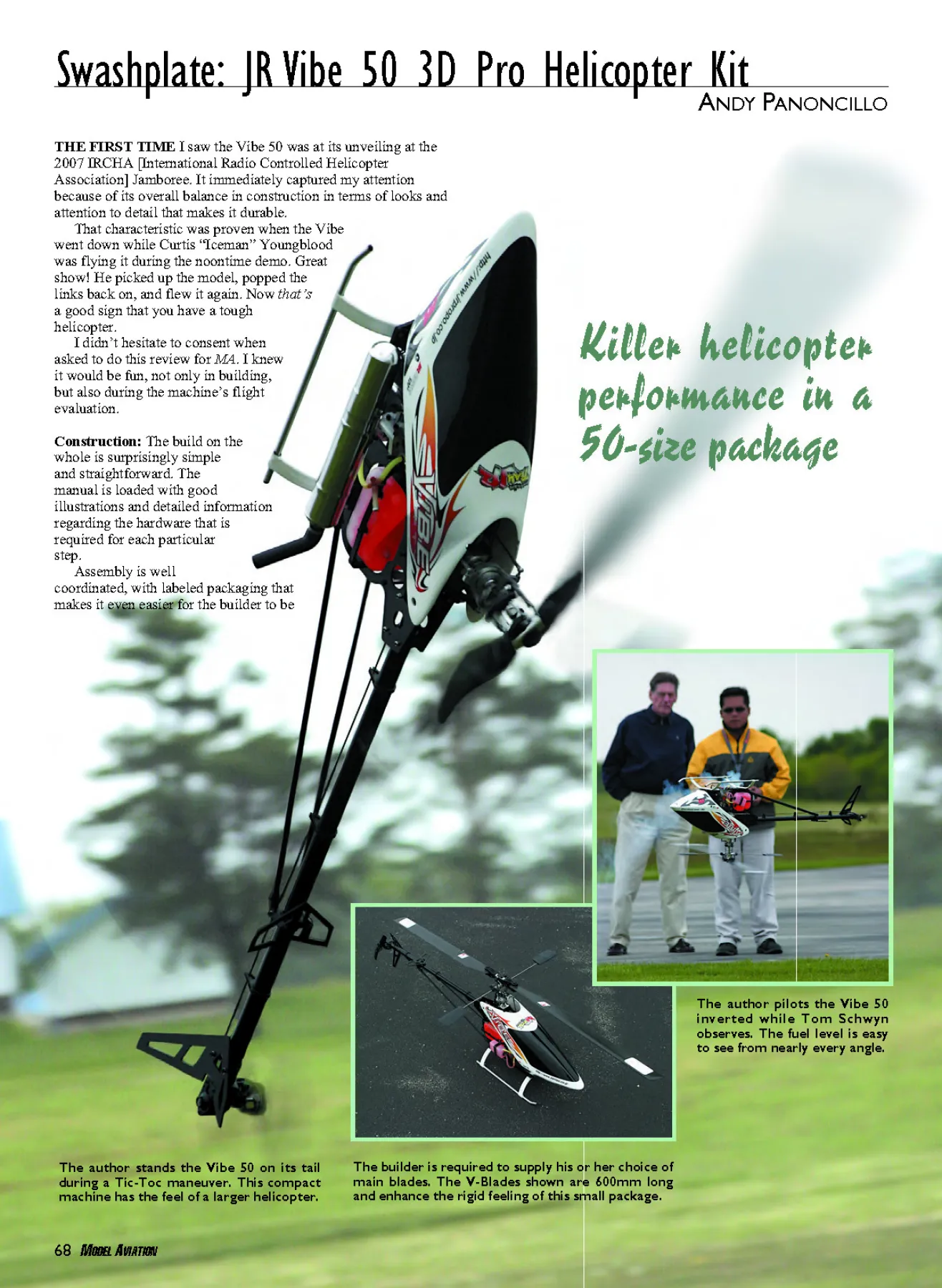
The author stands the Vibe 50 on its tail
during a Tic-Toc maneuver. This compact
machine has the feel of a larger helicopter.
The author pilots the Vibe 50
inverted while Tom Schwyn
observes. The fuel level is easy
to see from nearly every angle.
04sig3.QXD 2/24/09 1:45 PM Page 68
April 2009 69
To assure proper alignment, tighten bearing blocks against the
G10 frame sides with shaft temporarily installed.
Construction photos by the author Field and flight photos by Michael Ramsey
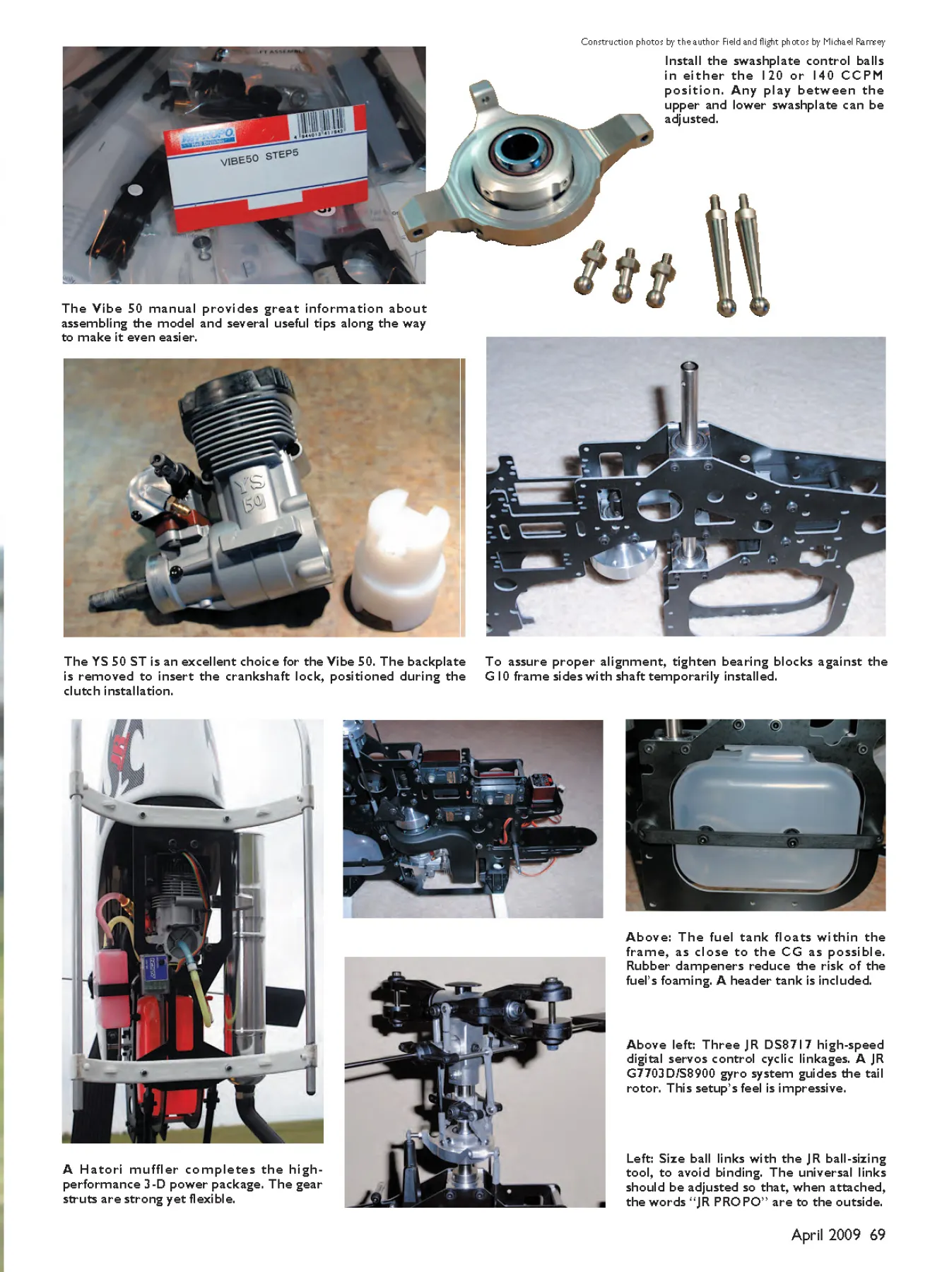
Install the swashplate control balls
in either the 120 or 140 CCPM
position. Any play between the
upper and lower swashplate can be
adjusted.
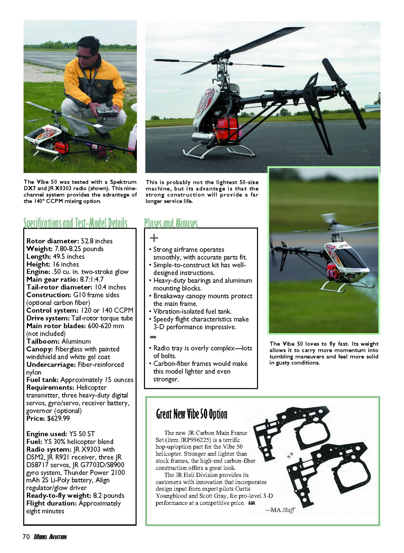
The YS 50 ST is an excellent choice for the Vibe 50. The backplate
is removed to insert the crankshaft lock, positioned during the
clutch installation.
A Hatori muffler completes the highperformance
3-D power package. The gear
struts are strong yet flexible.
Left: Size ball links with the JR ball-sizing
tool, to avoid binding. The universal links
should be adjusted so that, when attached,
the words “JR PROPO” are to the outside.
Above left: Three JR DS8717 high-speed
digital servos control cyclic linkages. A JR
G7703D/S8900 gyro system guides the tail
rotor. This setup’s feel is impressive.
Above: The fuel tank floats within the
frame, as close to the CG as possible.
Rubber dampeners reduce the risk of the
fuel’s foaming. A header tank is included.
The Vibe 50 manual provides great information about
assembling the model and several useful tips along the way
to make it even easier.
04sig3.QXD 2/24/09 1:55 PM Page 69
70 MODEL AVIATION
+
• Strong airframe operates
smoothly, with accurate parts fit.
• Simple-to-construct kit has welldesigned
instructions.
• Heavy-duty bearings and aluminum
mounting blocks.
• Breakaway canopy mounts protect
the main frame.
• Vibration-isolated fuel tank.
• Speedy flight characteristics make
3-D performance impressive. -• Radio tray is overly complex—lots
of bolts.
• Carbon-fiber frames would make
this model lighter and even
stronger.
Pluses and Minuses
The Vibe 50 was tested with a Spektrum
DX7 and JR X9303 radio (shown). This ninechannel
system provides the advantage of
the 140° CCPM mixing option.
This is probably not the lightest 50-size
machine, but its advantage is that the
strong construction will provide a far
longer service life.
Rotor diameter: 52.8 inches
Weight: 7.80-8.25 pounds
Length: 49.5 inches
Height: 16 inches
Engine: .50 cu. in. two-stroke glow
Main gear ratio: 8.7:1:4.7
Tail-rotor diameter: 10.4 inches
Construction: G10 frame sides
(optional carbon fiber)
Control system: 120 or 140 CCPM
Drive system: Tail-rotor torque tube
Main rotor blades: 600-620 mm
(not included)
Tailboom: Aluminum
Canopy: Fiberglass with painted
windshield and white gel coat
Undercarriage: Fiber-reinforced
nylon
Fuel tank: Approximately 15 ounces
Requirements: Helicopter
transmitter, three heavy-duty digital
servos, gyro/servo, receiver battery,
governor (optional)
Price: $629.99
Engine used: YS 50 ST
Fuel: YS 30% helicopter blend
Radio system: JR X9303 with
DSM2, JR R921 receiver, three JR
DS8717 servos, JR G7703D/S8900
gyro system, Thunder Power 2100
mAh 2S Li-Poly battery, Align
regulator/glow driver
Ready-to-fly weight: 8.2 pounds
Flight duration: Approximately
eight minutes
Specifications and Test-Model Details
Great New Vibe 50 Option
The Vibe 50 loves to fly fast. Its weight
allows it to carry more momentum into
tumbling maneuvers and feel more solid
in gusty conditions.
The new JR Carbon Main Frame
Set (item JRP996225) is a terrific
hop-up/option part for the Vibe 50
helicopter. Stronger and lighter than
stock frames, the high-end carbon-fiber
construction offers a great look.
The JR Heli Division provides its
customers with innovation that incorporates
design input from expert pilots Curtis
Youngblood and Scott Gray, for pro-level 3-D
performance at a competitive price. MA
—MA Staff
04sig3.QXD 2/24/09 2:12 PM Page 70
confident during the process. The kit also
comes with two grades of thread-locking
compound.
Construction begins with the clutch bell
and starter-shaft assembly. The hex-shaped
adapter doubles as a locking mechanism, to
keep assembly secure. The clutch bell
includes a mount for a governor magnet that
maintains balance because of the placement
of a second magnet 180° from the other. I
confirmed that fact on my pinpoint balancer.
Two plastic housings sandwich the nylon
tail pinion and pinion shaft within a bearing
assembly. It was good to see that JR
continued the tradition of using the
crossmember to strengthen this assembly,
since it is often subjected to heavy loads.
The bevel gear is preassembled and the tail
pinion shaft is prepinned, creating a mesh
between the gears that feels smooth and true.
The ball joints that fit into the plastic
parts are a tight and secure fit. Decide early
whether to use 120° or 140° Cyclic/
Collective Pitch Mixing (CCPM), because
the T-arms and elevator arms must match.
Check your radio; not every transmitter
features 140° mixing.
I like that the dual-stage main gear is
labeled right-side up; this eliminates any
confusion when completing the autorotation
assembly. That’s an extremely beefy design,
by the way. Make sure the autorotation
spacer is step-side down. It is well illustrated
in the manual.
The fuel tank is located in a visible
location, close to the CG. The assembly
includes nearly foolproof hardware that
assures a leak-free seal.
I would love to have a fuel magnet here
instead of a regular clunk. Using a fuel
magnet eliminates the need for a header
tank. The fuel tank is suspended between the
frames with a tank holder made from rubber,
making it less susceptible to foaming.
The side frames are not interchangeable.
To be honest, I did assemble them backward
and had to go back several steps to make the
correction.
The three bearing blocks with the clutch
bell assembly sets the frame halves in
position. Hardened-steel 3 x 8mm bolts with
flat 3mm washers secure the frames against
the bearing blocks. I installed the governor
mount on the left side. I slid the main shaft
through those two bearing blocks to ensure
that two frames were initially aligned well.
The frame parts are not fully tightened
and secured with thread lock until all the
bracing and block housings are located.
There is a total of six crossmembers.
The elevator arm is secured against the
frame using its spindle. The spindle does
have a notch on it for the setscrew to grab
when tightened. Observe through the main
frame that the elevator arm is positioned at
90° to the A-arm. A longer hex driver does
help with this step.
The body catch and standoff for the
canopy are designed to break away in the
event of a crash. This is an excellent
forethought; it will protect the frame from
damage. The engine mount is a one-piece
aluminum block that makes it easier to set
squarely against the frame.
The landing struts and adapter are
supported with 32mm-long crossmembers
bolted with 3 x 12mm and 3 x 50mm sockethead
bolts. The skids are bolted against the
strut with 3 x 4mm grub screws. The bottom
frame plate is bolted against the bottom of
the engine mount with 3 x 8mm socket-head
screws that sandwich the landing gear in
place.
Set the main gear and main shaft in
place, ensuring that the main shaft collar
eliminates any vertical play. With that step
complete, go back and tighten all the bolts
with thread-locking compound.
The quality of the CNC-machined
aluminum swashplate is a good example of
how well the Vibe 50 is designed. I noticed
no irregular play, and it is very smooth.
Three setscrews located on the swashplate
can be tightened if play develops later.
There are two sets of aileron and pitch
swashplate linkages. The longer set is for
140° and the shorter set is for the 120°
CCPM setup. The washout base is made
from aluminum, and it slides through the
main shaft smoothly, even without lubricant.
Both mixing arms have a total of four
bearings that provide smooth operation, but
I like the use of a 3mm nut that keeps the 3 x
14mm socket-head bolts against the main
blade grip. If those links loosen, the problem
could be fatal to the machine.
The plastic main blade grips are beefy
enough to be strong and capable. I like how
the manual provides good illustrations for
positioning the 8 x 14 x 4mm bearing, thrust
bearings, O-ring dampeners, and spacers in
the correct order. Not following this
sequence can lead to serious problems down
the road.
The one-piece, high-tilt flybar arm and
one-piece universal ball link are just a
couple of the many things I’m glad JR
applied to the Vibe 50. Although the flybar
is labeled 440mm, mine is shorter for some
reason. I installed it regardless; it would be
easy to replace later. The paddles do come
with removable weights that I replaced later,
in favor of a more sensitive setup.
The CNC-machined aluminum head
assembly is installed on the 10mm main
shaft and secured with a single 3 x 22mm
socket-head bolt and lock nut. That is
commonplace.
However, I’d rather see either a second
bolt or maybe a bolt that would clamp the
head onto the main shaft so that a single
“Jesus bolt” is not taking the entire load.
This would provide extra security and peace
of mind. Let’s face it; we do fly the 50-size
machines considerably more aggressively.
For the control rods, the builder simply
needs to match the links directly according
to the manual’s illustrations. I found that I
needed a ball-sizing tool to make sure that
all the links moved freely.
The tail-drive shaft assembly requires
only three simple steps. The aluminum shaft
floats inside the aluminum tailboom within
bearings that are isolated with rubber
grommets. It’s a simple enough setup that I
believe will hold up well against the
beatings that sudden changes in tail direction
induce.
A small amount of oil or grease on the
bearing holders makes sliding the drive shaft
fairly easy. The way JR designed the driveshaft
joint creates a solid feel.
The overall tail-gear assembly is bigger
and stronger than that of most other 50-
class machines on the market, which
contributes to the Vibe’s general integrity
and confidence. The tail fins (horizontal
and vertical) are made from G10 material
that could have been made from thinner
material and saved weight.
The manual provides detailed
instructions for both the dual-yoke tail-rotor
actuator and hub assembly. The tail-pitch
slider is not only incredibly smooth against
the tail output shaft, but it also moves freely
with the tail-pitch control lever—and I mean
extraordinarily smoothly, even without
lubrication.
The plastic tail-blade holders include
halves that are joined with four 2 x 10mm
socket-head bolts. This design makes it easy
to disassemble and regrease/oil the bearings.
The tailboom supports are simple to put
together and are guaranteed to be equal in
length because of their predrilled holes. The
manual recommends J.B. Weld, so I used
the five-minute formula.
Once assembled and installed, the tail
bellcrank provides enough throw; it is
smooth and exhibits no slop or binding. The
tail control rod is supported with three
guides. The Vibe 50 utilizes a flexible rod
with multiple guides to keep it in place and
operating smoothly.
I used the YS 50 ST engine with a Hatori
SAB-50 pipe. The engine slides up from the
bottom without having to remove the needle;
this makes maintenance a snap. The highefficiency
fan housing is self-aligning, with
enough clearance that there is no worry
about the fan’s rubbing in the shroud.
The kit came with servo mounting plates
and self-tapping screws. I’d prefer to use a
socket-head screw against a lock nut. During
regular maintenance, there is less chance of
stripping when using a lock nut security
system.
The servo locations are well laid out. The
kit even came with servo wheels that I found
handy for the push-pull linkages. Choose
servo arms that follow the rule of 90 as
closely as possible, to avoid large trim
adjustment from the transmitter.
The manual provides exact control rod
measurements from the servos to the Tarms.
This proved to be helpful; almost no
adjustment was needed.
Flight Characteristics: Flight tests began
with a hover, and the Vibe 50 showed that it
is stable and predictable. I set the governor
at 2,050 rpm for idle-up Number 1, which is
good for basic forward flight and
fundamental aerobatics. The helicopter
showed the ability to perform stable and
predictable flight.
The Vibe 50 can carry speed well and
track straight. While testing backward rightside-
up and backward inverted flight
maneuvers, I was amazed by how stable it
performed. The JR G770 3D gyro seemed to
work well with the ability to hold the tail
steady.
If you love 3-D as I do, don’t let this
helicopter’s weight deceive you. At first I
thought it would make the Vibe 50 a
collective management nightmare, but the
model maintained a great deal of authority
and speed. The extra weight actually helps it
perform the 3-D maneuvers that need speed,
such as the Hurricane, Funnel, Tic-Toc, and
others.
My cyclic setup is noticeably quick, so
the helicopter proved to be predictable and
locked into one place fairly easily during
Pirouetting Flips or the Chaos. Tailslide
maneuvers are even more dramatic because
of the model’s ability to carry speed in the
descent. This was on only the first tank of
fuel, mind you.
The second, third, and fourth flights on
the Vibe 50’s first day out became even
more enjoyable, because I got used to its
capability. It’s certainly a helicopter that
people should try.
On another day, I observed this model’s
durability test when I accidentally touched the
grass with it inverted in a hover. The only
damage was to the main shaft. Amazing!
I’d like to see carbon frames become
available for this helicopter, because they
would definitely make it even more fun
to fly. In the meantime, the JR Vibe 50 is
a great model that is strong in
construction and can provide any RC
helicopter pilot with less maintenance to
worry about. MA
Andy Panoncillo
[email protected]
Manufacturer/Distributor:
JR/Horizon Hobby Inc.
4105 Fieldstone Rd.
Champaign IL 61822
(800) 338-4639
www.jrradios.com
Items Used in Review:
YS 50 ST engine:
YS Parts and Service
(775) 267-9252
www.yspartsandservice.com
Hatori muffler systems:
Ron’s Heliproz South
(800) 321-9909
www.ronlund.com
Thunder Power batteries:
Thunder Power RC
(702) 228-8883
www.thunderpowerrc.com
Other Published Reviews:
Model Helicopter World: September 2008
Edition: Model Aviation - 2009/04
Page Numbers: 68,69,70,72,74,77
Edition: Model Aviation - 2009/04
Page Numbers: 68,69,70,72,74,77
68 MODEL AVIATION
ANDY PANONCILLO
Swashplate: JR Vibe 50 3D Pro Helicopter Kit
Killer helicopter
performance in a
50-size package
THE FIRST TIME I saw the Vibe 50 was at its unveiling at the
2007 IRCHA [International Radio Controlled Helicopter
Association] Jamboree. It immediately captured my attention
because of its overall balance in construction in terms of looks and
attention to detail that makes it durable.
That characteristic was proven when the Vibe
went down while Curtis “Iceman” Youngblood
was flying it during the noontime demo. Great
show! He picked up the model, popped the
links back on, and flew it again. Now that’s
a good sign that you have a tough
helicopter.
I didn’t hesitate to consent when
asked to do this review for MA. I knew
it would be fun, not only in building,
but also during the machine’s flight
evaluation.
Construction: The build on the
whole is surprisingly simple
and straightforward. The
manual is loaded with good
illustrations and detailed information
regarding the hardware that is
required for each particular
step.
Assembly is well
coordinated, with labeled packaging that
makes it even easier for the builder to be
The builder is required to supply his or her choice of
main blades. The V-Blades shown are 600mm long
and enhance the rigid feeling of this small package.
The author stands the Vibe 50 on its tail
during a Tic-Toc maneuver. This compact
machine has the feel of a larger helicopter.
The author pilots the Vibe 50
inverted while Tom Schwyn
observes. The fuel level is easy
to see from nearly every angle.
04sig3.QXD 2/24/09 1:45 PM Page 68
April 2009 69
To assure proper alignment, tighten bearing blocks against the
G10 frame sides with shaft temporarily installed.
Construction photos by the author Field and flight photos by Michael Ramsey
Install the swashplate control balls
in either the 120 or 140 CCPM
position. Any play between the
upper and lower swashplate can be
adjusted.
The YS 50 ST is an excellent choice for the Vibe 50. The backplate
is removed to insert the crankshaft lock, positioned during the
clutch installation.
A Hatori muffler completes the highperformance
3-D power package. The gear
struts are strong yet flexible.
Left: Size ball links with the JR ball-sizing
tool, to avoid binding. The universal links
should be adjusted so that, when attached,
the words “JR PROPO” are to the outside.
Above left: Three JR DS8717 high-speed
digital servos control cyclic linkages. A JR
G7703D/S8900 gyro system guides the tail
rotor. This setup’s feel is impressive.
Above: The fuel tank floats within the
frame, as close to the CG as possible.
Rubber dampeners reduce the risk of the
fuel’s foaming. A header tank is included.
The Vibe 50 manual provides great information about
assembling the model and several useful tips along the way
to make it even easier.
04sig3.QXD 2/24/09 1:55 PM Page 69
70 MODEL AVIATION
+
• Strong airframe operates
smoothly, with accurate parts fit.
• Simple-to-construct kit has welldesigned
instructions.
• Heavy-duty bearings and aluminum
mounting blocks.
• Breakaway canopy mounts protect
the main frame.
• Vibration-isolated fuel tank.
• Speedy flight characteristics make
3-D performance impressive. -• Radio tray is overly complex—lots
of bolts.
• Carbon-fiber frames would make
this model lighter and even
stronger.
Pluses and Minuses
The Vibe 50 was tested with a Spektrum
DX7 and JR X9303 radio (shown). This ninechannel
system provides the advantage of
the 140° CCPM mixing option.
This is probably not the lightest 50-size
machine, but its advantage is that the
strong construction will provide a far
longer service life.
Rotor diameter: 52.8 inches
Weight: 7.80-8.25 pounds
Length: 49.5 inches
Height: 16 inches
Engine: .50 cu. in. two-stroke glow
Main gear ratio: 8.7:1:4.7
Tail-rotor diameter: 10.4 inches
Construction: G10 frame sides
(optional carbon fiber)
Control system: 120 or 140 CCPM
Drive system: Tail-rotor torque tube
Main rotor blades: 600-620 mm
(not included)
Tailboom: Aluminum
Canopy: Fiberglass with painted
windshield and white gel coat
Undercarriage: Fiber-reinforced
nylon
Fuel tank: Approximately 15 ounces
Requirements: Helicopter
transmitter, three heavy-duty digital
servos, gyro/servo, receiver battery,
governor (optional)
Price: $629.99
Engine used: YS 50 ST
Fuel: YS 30% helicopter blend
Radio system: JR X9303 with
DSM2, JR R921 receiver, three JR
DS8717 servos, JR G7703D/S8900
gyro system, Thunder Power 2100
mAh 2S Li-Poly battery, Align
regulator/glow driver
Ready-to-fly weight: 8.2 pounds
Flight duration: Approximately
eight minutes
Specifications and Test-Model Details
Great New Vibe 50 Option
The Vibe 50 loves to fly fast. Its weight
allows it to carry more momentum into
tumbling maneuvers and feel more solid
in gusty conditions.
The new JR Carbon Main Frame
Set (item JRP996225) is a terrific
hop-up/option part for the Vibe 50
helicopter. Stronger and lighter than
stock frames, the high-end carbon-fiber
construction offers a great look.
The JR Heli Division provides its
customers with innovation that incorporates
design input from expert pilots Curtis
Youngblood and Scott Gray, for pro-level 3-D
performance at a competitive price. MA
—MA Staff
04sig3.QXD 2/24/09 2:12 PM Page 70
confident during the process. The kit also
comes with two grades of thread-locking
compound.
Construction begins with the clutch bell
and starter-shaft assembly. The hex-shaped
adapter doubles as a locking mechanism, to
keep assembly secure. The clutch bell
includes a mount for a governor magnet that
maintains balance because of the placement
of a second magnet 180° from the other. I
confirmed that fact on my pinpoint balancer.
Two plastic housings sandwich the nylon
tail pinion and pinion shaft within a bearing
assembly. It was good to see that JR
continued the tradition of using the
crossmember to strengthen this assembly,
since it is often subjected to heavy loads.
The bevel gear is preassembled and the tail
pinion shaft is prepinned, creating a mesh
between the gears that feels smooth and true.
The ball joints that fit into the plastic
parts are a tight and secure fit. Decide early
whether to use 120° or 140° Cyclic/
Collective Pitch Mixing (CCPM), because
the T-arms and elevator arms must match.
Check your radio; not every transmitter
features 140° mixing.
I like that the dual-stage main gear is
labeled right-side up; this eliminates any
confusion when completing the autorotation
assembly. That’s an extremely beefy design,
by the way. Make sure the autorotation
spacer is step-side down. It is well illustrated
in the manual.
The fuel tank is located in a visible
location, close to the CG. The assembly
includes nearly foolproof hardware that
assures a leak-free seal.
I would love to have a fuel magnet here
instead of a regular clunk. Using a fuel
magnet eliminates the need for a header
tank. The fuel tank is suspended between the
frames with a tank holder made from rubber,
making it less susceptible to foaming.
The side frames are not interchangeable.
To be honest, I did assemble them backward
and had to go back several steps to make the
correction.
The three bearing blocks with the clutch
bell assembly sets the frame halves in
position. Hardened-steel 3 x 8mm bolts with
flat 3mm washers secure the frames against
the bearing blocks. I installed the governor
mount on the left side. I slid the main shaft
through those two bearing blocks to ensure
that two frames were initially aligned well.
The frame parts are not fully tightened
and secured with thread lock until all the
bracing and block housings are located.
There is a total of six crossmembers.
The elevator arm is secured against the
frame using its spindle. The spindle does
have a notch on it for the setscrew to grab
when tightened. Observe through the main
frame that the elevator arm is positioned at
90° to the A-arm. A longer hex driver does
help with this step.
The body catch and standoff for the
canopy are designed to break away in the
event of a crash. This is an excellent
forethought; it will protect the frame from
damage. The engine mount is a one-piece
aluminum block that makes it easier to set
squarely against the frame.
The landing struts and adapter are
supported with 32mm-long crossmembers
bolted with 3 x 12mm and 3 x 50mm sockethead
bolts. The skids are bolted against the
strut with 3 x 4mm grub screws. The bottom
frame plate is bolted against the bottom of
the engine mount with 3 x 8mm socket-head
screws that sandwich the landing gear in
place.
Set the main gear and main shaft in
place, ensuring that the main shaft collar
eliminates any vertical play. With that step
complete, go back and tighten all the bolts
with thread-locking compound.
The quality of the CNC-machined
aluminum swashplate is a good example of
how well the Vibe 50 is designed. I noticed
no irregular play, and it is very smooth.
Three setscrews located on the swashplate
can be tightened if play develops later.
There are two sets of aileron and pitch
swashplate linkages. The longer set is for
140° and the shorter set is for the 120°
CCPM setup. The washout base is made
from aluminum, and it slides through the
main shaft smoothly, even without lubricant.
Both mixing arms have a total of four
bearings that provide smooth operation, but
I like the use of a 3mm nut that keeps the 3 x
14mm socket-head bolts against the main
blade grip. If those links loosen, the problem
could be fatal to the machine.
The plastic main blade grips are beefy
enough to be strong and capable. I like how
the manual provides good illustrations for
positioning the 8 x 14 x 4mm bearing, thrust
bearings, O-ring dampeners, and spacers in
the correct order. Not following this
sequence can lead to serious problems down
the road.
The one-piece, high-tilt flybar arm and
one-piece universal ball link are just a
couple of the many things I’m glad JR
applied to the Vibe 50. Although the flybar
is labeled 440mm, mine is shorter for some
reason. I installed it regardless; it would be
easy to replace later. The paddles do come
with removable weights that I replaced later,
in favor of a more sensitive setup.
The CNC-machined aluminum head
assembly is installed on the 10mm main
shaft and secured with a single 3 x 22mm
socket-head bolt and lock nut. That is
commonplace.
However, I’d rather see either a second
bolt or maybe a bolt that would clamp the
head onto the main shaft so that a single
“Jesus bolt” is not taking the entire load.
This would provide extra security and peace
of mind. Let’s face it; we do fly the 50-size
machines considerably more aggressively.
For the control rods, the builder simply
needs to match the links directly according
to the manual’s illustrations. I found that I
needed a ball-sizing tool to make sure that
all the links moved freely.
The tail-drive shaft assembly requires
only three simple steps. The aluminum shaft
floats inside the aluminum tailboom within
bearings that are isolated with rubber
grommets. It’s a simple enough setup that I
believe will hold up well against the
beatings that sudden changes in tail direction
induce.
A small amount of oil or grease on the
bearing holders makes sliding the drive shaft
fairly easy. The way JR designed the driveshaft
joint creates a solid feel.
The overall tail-gear assembly is bigger
and stronger than that of most other 50-
class machines on the market, which
contributes to the Vibe’s general integrity
and confidence. The tail fins (horizontal
and vertical) are made from G10 material
that could have been made from thinner
material and saved weight.
The manual provides detailed
instructions for both the dual-yoke tail-rotor
actuator and hub assembly. The tail-pitch
slider is not only incredibly smooth against
the tail output shaft, but it also moves freely
with the tail-pitch control lever—and I mean
extraordinarily smoothly, even without
lubrication.
The plastic tail-blade holders include
halves that are joined with four 2 x 10mm
socket-head bolts. This design makes it easy
to disassemble and regrease/oil the bearings.
The tailboom supports are simple to put
together and are guaranteed to be equal in
length because of their predrilled holes. The
manual recommends J.B. Weld, so I used
the five-minute formula.
Once assembled and installed, the tail
bellcrank provides enough throw; it is
smooth and exhibits no slop or binding. The
tail control rod is supported with three
guides. The Vibe 50 utilizes a flexible rod
with multiple guides to keep it in place and
operating smoothly.
I used the YS 50 ST engine with a Hatori
SAB-50 pipe. The engine slides up from the
bottom without having to remove the needle;
this makes maintenance a snap. The highefficiency
fan housing is self-aligning, with
enough clearance that there is no worry
about the fan’s rubbing in the shroud.
The kit came with servo mounting plates
and self-tapping screws. I’d prefer to use a
socket-head screw against a lock nut. During
regular maintenance, there is less chance of
stripping when using a lock nut security
system.
The servo locations are well laid out. The
kit even came with servo wheels that I found
handy for the push-pull linkages. Choose
servo arms that follow the rule of 90 as
closely as possible, to avoid large trim
adjustment from the transmitter.
The manual provides exact control rod
measurements from the servos to the Tarms.
This proved to be helpful; almost no
adjustment was needed.
Flight Characteristics: Flight tests began
with a hover, and the Vibe 50 showed that it
is stable and predictable. I set the governor
at 2,050 rpm for idle-up Number 1, which is
good for basic forward flight and
fundamental aerobatics. The helicopter
showed the ability to perform stable and
predictable flight.
The Vibe 50 can carry speed well and
track straight. While testing backward rightside-
up and backward inverted flight
maneuvers, I was amazed by how stable it
performed. The JR G770 3D gyro seemed to
work well with the ability to hold the tail
steady.
If you love 3-D as I do, don’t let this
helicopter’s weight deceive you. At first I
thought it would make the Vibe 50 a
collective management nightmare, but the
model maintained a great deal of authority
and speed. The extra weight actually helps it
perform the 3-D maneuvers that need speed,
such as the Hurricane, Funnel, Tic-Toc, and
others.
My cyclic setup is noticeably quick, so
the helicopter proved to be predictable and
locked into one place fairly easily during
Pirouetting Flips or the Chaos. Tailslide
maneuvers are even more dramatic because
of the model’s ability to carry speed in the
descent. This was on only the first tank of
fuel, mind you.
The second, third, and fourth flights on
the Vibe 50’s first day out became even
more enjoyable, because I got used to its
capability. It’s certainly a helicopter that
people should try.
On another day, I observed this model’s
durability test when I accidentally touched the
grass with it inverted in a hover. The only
damage was to the main shaft. Amazing!
I’d like to see carbon frames become
available for this helicopter, because they
would definitely make it even more fun
to fly. In the meantime, the JR Vibe 50 is
a great model that is strong in
construction and can provide any RC
helicopter pilot with less maintenance to
worry about. MA
Andy Panoncillo
[email protected]
Manufacturer/Distributor:
JR/Horizon Hobby Inc.
4105 Fieldstone Rd.
Champaign IL 61822
(800) 338-4639
www.jrradios.com
Items Used in Review:
YS 50 ST engine:
YS Parts and Service
(775) 267-9252
www.yspartsandservice.com
Hatori muffler systems:
Ron’s Heliproz South
(800) 321-9909
www.ronlund.com
Thunder Power batteries:
Thunder Power RC
(702) 228-8883
www.thunderpowerrc.com
Other Published Reviews:
Model Helicopter World: September 2008
Edition: Model Aviation - 2009/04
Page Numbers: 68,69,70,72,74,77
68 MODEL AVIATION
ANDY PANONCILLO
Swashplate: JR Vibe 50 3D Pro Helicopter Kit
Killer helicopter
performance in a
50-size package
THE FIRST TIME I saw the Vibe 50 was at its unveiling at the
2007 IRCHA [International Radio Controlled Helicopter
Association] Jamboree. It immediately captured my attention
because of its overall balance in construction in terms of looks and
attention to detail that makes it durable.
That characteristic was proven when the Vibe
went down while Curtis “Iceman” Youngblood
was flying it during the noontime demo. Great
show! He picked up the model, popped the
links back on, and flew it again. Now that’s
a good sign that you have a tough
helicopter.
I didn’t hesitate to consent when
asked to do this review for MA. I knew
it would be fun, not only in building,
but also during the machine’s flight
evaluation.
Construction: The build on the
whole is surprisingly simple
and straightforward. The
manual is loaded with good
illustrations and detailed information
regarding the hardware that is
required for each particular
step.
Assembly is well
coordinated, with labeled packaging that
makes it even easier for the builder to be
The builder is required to supply his or her choice of
main blades. The V-Blades shown are 600mm long
and enhance the rigid feeling of this small package.
The author stands the Vibe 50 on its tail
during a Tic-Toc maneuver. This compact
machine has the feel of a larger helicopter.
The author pilots the Vibe 50
inverted while Tom Schwyn
observes. The fuel level is easy
to see from nearly every angle.
04sig3.QXD 2/24/09 1:45 PM Page 68
April 2009 69
To assure proper alignment, tighten bearing blocks against the
G10 frame sides with shaft temporarily installed.
Construction photos by the author Field and flight photos by Michael Ramsey
Install the swashplate control balls
in either the 120 or 140 CCPM
position. Any play between the
upper and lower swashplate can be
adjusted.
The YS 50 ST is an excellent choice for the Vibe 50. The backplate
is removed to insert the crankshaft lock, positioned during the
clutch installation.
A Hatori muffler completes the highperformance
3-D power package. The gear
struts are strong yet flexible.
Left: Size ball links with the JR ball-sizing
tool, to avoid binding. The universal links
should be adjusted so that, when attached,
the words “JR PROPO” are to the outside.
Above left: Three JR DS8717 high-speed
digital servos control cyclic linkages. A JR
G7703D/S8900 gyro system guides the tail
rotor. This setup’s feel is impressive.
Above: The fuel tank floats within the
frame, as close to the CG as possible.
Rubber dampeners reduce the risk of the
fuel’s foaming. A header tank is included.
The Vibe 50 manual provides great information about
assembling the model and several useful tips along the way
to make it even easier.
04sig3.QXD 2/24/09 1:55 PM Page 69
70 MODEL AVIATION
+
• Strong airframe operates
smoothly, with accurate parts fit.
• Simple-to-construct kit has welldesigned
instructions.
• Heavy-duty bearings and aluminum
mounting blocks.
• Breakaway canopy mounts protect
the main frame.
• Vibration-isolated fuel tank.
• Speedy flight characteristics make
3-D performance impressive. -• Radio tray is overly complex—lots
of bolts.
• Carbon-fiber frames would make
this model lighter and even
stronger.
Pluses and Minuses
The Vibe 50 was tested with a Spektrum
DX7 and JR X9303 radio (shown). This ninechannel
system provides the advantage of
the 140° CCPM mixing option.
This is probably not the lightest 50-size
machine, but its advantage is that the
strong construction will provide a far
longer service life.
Rotor diameter: 52.8 inches
Weight: 7.80-8.25 pounds
Length: 49.5 inches
Height: 16 inches
Engine: .50 cu. in. two-stroke glow
Main gear ratio: 8.7:1:4.7
Tail-rotor diameter: 10.4 inches
Construction: G10 frame sides
(optional carbon fiber)
Control system: 120 or 140 CCPM
Drive system: Tail-rotor torque tube
Main rotor blades: 600-620 mm
(not included)
Tailboom: Aluminum
Canopy: Fiberglass with painted
windshield and white gel coat
Undercarriage: Fiber-reinforced
nylon
Fuel tank: Approximately 15 ounces
Requirements: Helicopter
transmitter, three heavy-duty digital
servos, gyro/servo, receiver battery,
governor (optional)
Price: $629.99
Engine used: YS 50 ST
Fuel: YS 30% helicopter blend
Radio system: JR X9303 with
DSM2, JR R921 receiver, three JR
DS8717 servos, JR G7703D/S8900
gyro system, Thunder Power 2100
mAh 2S Li-Poly battery, Align
regulator/glow driver
Ready-to-fly weight: 8.2 pounds
Flight duration: Approximately
eight minutes
Specifications and Test-Model Details
Great New Vibe 50 Option
The Vibe 50 loves to fly fast. Its weight
allows it to carry more momentum into
tumbling maneuvers and feel more solid
in gusty conditions.
The new JR Carbon Main Frame
Set (item JRP996225) is a terrific
hop-up/option part for the Vibe 50
helicopter. Stronger and lighter than
stock frames, the high-end carbon-fiber
construction offers a great look.
The JR Heli Division provides its
customers with innovation that incorporates
design input from expert pilots Curtis
Youngblood and Scott Gray, for pro-level 3-D
performance at a competitive price. MA
—MA Staff
04sig3.QXD 2/24/09 2:12 PM Page 70
confident during the process. The kit also
comes with two grades of thread-locking
compound.
Construction begins with the clutch bell
and starter-shaft assembly. The hex-shaped
adapter doubles as a locking mechanism, to
keep assembly secure. The clutch bell
includes a mount for a governor magnet that
maintains balance because of the placement
of a second magnet 180° from the other. I
confirmed that fact on my pinpoint balancer.
Two plastic housings sandwich the nylon
tail pinion and pinion shaft within a bearing
assembly. It was good to see that JR
continued the tradition of using the
crossmember to strengthen this assembly,
since it is often subjected to heavy loads.
The bevel gear is preassembled and the tail
pinion shaft is prepinned, creating a mesh
between the gears that feels smooth and true.
The ball joints that fit into the plastic
parts are a tight and secure fit. Decide early
whether to use 120° or 140° Cyclic/
Collective Pitch Mixing (CCPM), because
the T-arms and elevator arms must match.
Check your radio; not every transmitter
features 140° mixing.
I like that the dual-stage main gear is
labeled right-side up; this eliminates any
confusion when completing the autorotation
assembly. That’s an extremely beefy design,
by the way. Make sure the autorotation
spacer is step-side down. It is well illustrated
in the manual.
The fuel tank is located in a visible
location, close to the CG. The assembly
includes nearly foolproof hardware that
assures a leak-free seal.
I would love to have a fuel magnet here
instead of a regular clunk. Using a fuel
magnet eliminates the need for a header
tank. The fuel tank is suspended between the
frames with a tank holder made from rubber,
making it less susceptible to foaming.
The side frames are not interchangeable.
To be honest, I did assemble them backward
and had to go back several steps to make the
correction.
The three bearing blocks with the clutch
bell assembly sets the frame halves in
position. Hardened-steel 3 x 8mm bolts with
flat 3mm washers secure the frames against
the bearing blocks. I installed the governor
mount on the left side. I slid the main shaft
through those two bearing blocks to ensure
that two frames were initially aligned well.
The frame parts are not fully tightened
and secured with thread lock until all the
bracing and block housings are located.
There is a total of six crossmembers.
The elevator arm is secured against the
frame using its spindle. The spindle does
have a notch on it for the setscrew to grab
when tightened. Observe through the main
frame that the elevator arm is positioned at
90° to the A-arm. A longer hex driver does
help with this step.
The body catch and standoff for the
canopy are designed to break away in the
event of a crash. This is an excellent
forethought; it will protect the frame from
damage. The engine mount is a one-piece
aluminum block that makes it easier to set
squarely against the frame.
The landing struts and adapter are
supported with 32mm-long crossmembers
bolted with 3 x 12mm and 3 x 50mm sockethead
bolts. The skids are bolted against the
strut with 3 x 4mm grub screws. The bottom
frame plate is bolted against the bottom of
the engine mount with 3 x 8mm socket-head
screws that sandwich the landing gear in
place.
Set the main gear and main shaft in
place, ensuring that the main shaft collar
eliminates any vertical play. With that step
complete, go back and tighten all the bolts
with thread-locking compound.
The quality of the CNC-machined
aluminum swashplate is a good example of
how well the Vibe 50 is designed. I noticed
no irregular play, and it is very smooth.
Three setscrews located on the swashplate
can be tightened if play develops later.
There are two sets of aileron and pitch
swashplate linkages. The longer set is for
140° and the shorter set is for the 120°
CCPM setup. The washout base is made
from aluminum, and it slides through the
main shaft smoothly, even without lubricant.
Both mixing arms have a total of four
bearings that provide smooth operation, but
I like the use of a 3mm nut that keeps the 3 x
14mm socket-head bolts against the main
blade grip. If those links loosen, the problem
could be fatal to the machine.
The plastic main blade grips are beefy
enough to be strong and capable. I like how
the manual provides good illustrations for
positioning the 8 x 14 x 4mm bearing, thrust
bearings, O-ring dampeners, and spacers in
the correct order. Not following this
sequence can lead to serious problems down
the road.
The one-piece, high-tilt flybar arm and
one-piece universal ball link are just a
couple of the many things I’m glad JR
applied to the Vibe 50. Although the flybar
is labeled 440mm, mine is shorter for some
reason. I installed it regardless; it would be
easy to replace later. The paddles do come
with removable weights that I replaced later,
in favor of a more sensitive setup.
The CNC-machined aluminum head
assembly is installed on the 10mm main
shaft and secured with a single 3 x 22mm
socket-head bolt and lock nut. That is
commonplace.
However, I’d rather see either a second
bolt or maybe a bolt that would clamp the
head onto the main shaft so that a single
“Jesus bolt” is not taking the entire load.
This would provide extra security and peace
of mind. Let’s face it; we do fly the 50-size
machines considerably more aggressively.
For the control rods, the builder simply
needs to match the links directly according
to the manual’s illustrations. I found that I
needed a ball-sizing tool to make sure that
all the links moved freely.
The tail-drive shaft assembly requires
only three simple steps. The aluminum shaft
floats inside the aluminum tailboom within
bearings that are isolated with rubber
grommets. It’s a simple enough setup that I
believe will hold up well against the
beatings that sudden changes in tail direction
induce.
A small amount of oil or grease on the
bearing holders makes sliding the drive shaft
fairly easy. The way JR designed the driveshaft
joint creates a solid feel.
The overall tail-gear assembly is bigger
and stronger than that of most other 50-
class machines on the market, which
contributes to the Vibe’s general integrity
and confidence. The tail fins (horizontal
and vertical) are made from G10 material
that could have been made from thinner
material and saved weight.
The manual provides detailed
instructions for both the dual-yoke tail-rotor
actuator and hub assembly. The tail-pitch
slider is not only incredibly smooth against
the tail output shaft, but it also moves freely
with the tail-pitch control lever—and I mean
extraordinarily smoothly, even without
lubrication.
The plastic tail-blade holders include
halves that are joined with four 2 x 10mm
socket-head bolts. This design makes it easy
to disassemble and regrease/oil the bearings.
The tailboom supports are simple to put
together and are guaranteed to be equal in
length because of their predrilled holes. The
manual recommends J.B. Weld, so I used
the five-minute formula.
Once assembled and installed, the tail
bellcrank provides enough throw; it is
smooth and exhibits no slop or binding. The
tail control rod is supported with three
guides. The Vibe 50 utilizes a flexible rod
with multiple guides to keep it in place and
operating smoothly.
I used the YS 50 ST engine with a Hatori
SAB-50 pipe. The engine slides up from the
bottom without having to remove the needle;
this makes maintenance a snap. The highefficiency
fan housing is self-aligning, with
enough clearance that there is no worry
about the fan’s rubbing in the shroud.
The kit came with servo mounting plates
and self-tapping screws. I’d prefer to use a
socket-head screw against a lock nut. During
regular maintenance, there is less chance of
stripping when using a lock nut security
system.
The servo locations are well laid out. The
kit even came with servo wheels that I found
handy for the push-pull linkages. Choose
servo arms that follow the rule of 90 as
closely as possible, to avoid large trim
adjustment from the transmitter.
The manual provides exact control rod
measurements from the servos to the Tarms.
This proved to be helpful; almost no
adjustment was needed.
Flight Characteristics: Flight tests began
with a hover, and the Vibe 50 showed that it
is stable and predictable. I set the governor
at 2,050 rpm for idle-up Number 1, which is
good for basic forward flight and
fundamental aerobatics. The helicopter
showed the ability to perform stable and
predictable flight.
The Vibe 50 can carry speed well and
track straight. While testing backward rightside-
up and backward inverted flight
maneuvers, I was amazed by how stable it
performed. The JR G770 3D gyro seemed to
work well with the ability to hold the tail
steady.
If you love 3-D as I do, don’t let this
helicopter’s weight deceive you. At first I
thought it would make the Vibe 50 a
collective management nightmare, but the
model maintained a great deal of authority
and speed. The extra weight actually helps it
perform the 3-D maneuvers that need speed,
such as the Hurricane, Funnel, Tic-Toc, and
others.
My cyclic setup is noticeably quick, so
the helicopter proved to be predictable and
locked into one place fairly easily during
Pirouetting Flips or the Chaos. Tailslide
maneuvers are even more dramatic because
of the model’s ability to carry speed in the
descent. This was on only the first tank of
fuel, mind you.
The second, third, and fourth flights on
the Vibe 50’s first day out became even
more enjoyable, because I got used to its
capability. It’s certainly a helicopter that
people should try.
On another day, I observed this model’s
durability test when I accidentally touched the
grass with it inverted in a hover. The only
damage was to the main shaft. Amazing!
I’d like to see carbon frames become
available for this helicopter, because they
would definitely make it even more fun
to fly. In the meantime, the JR Vibe 50 is
a great model that is strong in
construction and can provide any RC
helicopter pilot with less maintenance to
worry about. MA
Andy Panoncillo
[email protected]
Manufacturer/Distributor:
JR/Horizon Hobby Inc.
4105 Fieldstone Rd.
Champaign IL 61822
(800) 338-4639
www.jrradios.com
Items Used in Review:
YS 50 ST engine:
YS Parts and Service
(775) 267-9252
www.yspartsandservice.com
Hatori muffler systems:
Ron’s Heliproz South
(800) 321-9909
www.ronlund.com
Thunder Power batteries:
Thunder Power RC
(702) 228-8883
www.thunderpowerrc.com
Other Published Reviews:
Model Helicopter World: September 2008

