
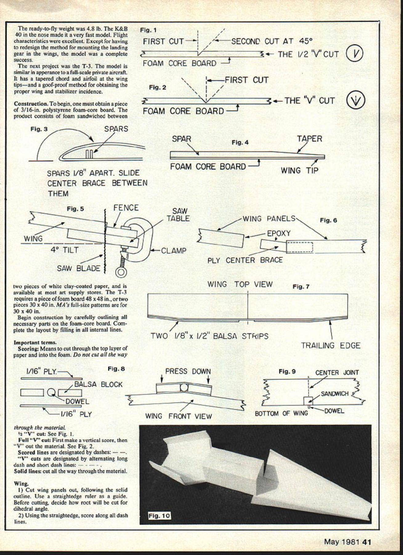
Clean lines th T-3 very similar modern full-scale private aircraft article profusely Illustrated 24 figures depicting aithors methods working foam-core board showing critical points constructing T-3 Figures keyed text ever-increasing price traditional model building materials no wonder creative people experimenting alternatives T-3 3-ch RC trainer 1 9-40 engines makes extensive use foam-core board obtainablefromartsupply storesE Ray Hawkinson SEVERAL years ago began experimenting use foam-core board aircraft modeling first substituted foam-core board balsa bulkheads formers ribs After observing characteristics material applications decided build entire model primarily foam-core board first fuselage constructed tradi tional manner using slab sides differ ence used foam-core board instead balsa method worked difficult hide exposed edges finally spackling com pound used filler resulted fairly satisfactory finish wing model first ribless design airfoil achieved folding foam-core board over spruce spar result symmetrical airfoil constant-chord wing successful forming rather thin airfoil seemed adequate horizontal stabilizer constructed double thickness foam-core board have discovered since neces sary single thickness provides adequate strength vertical fin constructed single thickness After finishing model yellow polyurethane paint striping tape loaded car headed flight field ran through pre Ilight check fired up HP 61 nose taxied out takeoff considerable apprehension about thin airfoil prepared myself hairy first flight Quite amazement thing lifted off smoothly After gaining some altitude began checking response various maneuvers Everything worked fine brought model landing though landing speed bit faster other models have final flare beautiful ship touched down taxied back delighted results After some minor adjustments made several flights About week later real test came begun really enjoy model suddenly radio failure model went slamming ground full bore hit wing tore away fuselage bounced violently along ground fuselage stuck ground like arrow arrived scene proceeded dig fuselage engine out Florida sand gathered up pieces headed home brought mess workshop removed radio engine left remains corner Some time later decided tackle repair work Since model built scratch hadnt bothered draw up plans nothing refer rebuilding crumpled nose except some badly bent foamcore board proceeded saw off remains first bulkhead flattened out bent pieces best could got some measurements two hours fuselage back piece wing repairs took less time next day model ready fly first model stimulated thinking convinced foam-core board very practical building material two de sign improvements felt necessary thicker airfoil elimination exposed foam-core edges fuselage airfoil problem solved cut-scoring surface material folding over spar wing second model designed have tapered airfoil tapered chord amazed easy get thicker symmetrical airfoil center joint wing panels matched up perfectly Another dividend able construct complex wing fraction time took construct either built-up wing wire-cut foam wing fuselage problem solved diagram ing outline foam-core board such way could folded together glued As wing panels scoring inside resulting clean smooth exterior surface glue joints sand smooth some experimentation discovered cut score fuselage order achieve desired dimensions after folding result fuselage apperance 1930 racer no exposed edges seal sand 40 Model Aviation ready-to-fly weight 48 lb K&B 40 nose made very fast model Flight characteristics excellent Except having redesign method mounting landing gear wings model complete success next project T-3 model similar apperance full-scale private aircraft has tapered chord airfoil wing tipsand goof-proof method obtaining proper wing stabilizer incidence Construction begin must obtain piece 3/16-in polystyrene foam-core board product consists foam sandwiched between Fig3SPARS SPARS 1/8 APART SLIDE CENTER BRACE BETWEEN THEM Fig1// FIRST CUT- ~SECOND CUT AT 450 FOAM CORE BOARD I/2VCUT Fig2UFIRST CUT I/ I/ FOAM CORE BOARD Fig 4 FOAM CORE BOARDI THE 11V81 CUT TAPER /1 WING TIP Fig5 WING 40 TILT SAW BLADE FENCESAW /TABLE IICLAMP 0 WING PANELS Fig6 Y PLY CENTER BRACE two pieces white clay-coated paper available art supply stores T-3 requires piece foam board 48 x 48 two pieces 30 x 40 MAs full-size patterns 30 x 40 Begin construction carefully outlining necessary parts foam-core board Com plete layout filling internal lines Important terms Scoring Means cut through top layer paper foam cut way 1/16 Fig 8 BALSA BLOCK 0DOWEL 1/16 PLY WING TOP VIEW 1 TWO 1/8 x 1/2 BALSA STRIPS PRESS DOWN WING FRONT VIEW Fig 7 TRAILING EDGE Fig 9 CENTER JOINT ISANEMIICH BOTTOM OF WING -DOWEL through material t See Fig 1 Full V cut First make vertical score V Out material See Fig 2 Scored lines designated dashes uts designated alternating long dash short dash lines id lines cut way through material Wing 1 Cut wing panels out following solid outline Use straightedge ruler gnide Before cutting decide root will cut dihedral angle 2 Using straightedge score along dash lines May 1981 41 0 3 V-out material along area behind leading edge Follow long-short dash lines 4 Glue spars foam-core board positions marked Note main spar tapered end Study Fig 3 5 Trial-fold top half wing over spars line up trailing edge Open fold again Spread glue leading edge V seam top spars trailing edge model completely built aliphatic resin such Sig-Bond specified 5-mm epoxy Fold wing panel closed clamp trailing edge See Fig 4 Note allow glue ooze space between spars ood center brace will go otherwise trouble will encountered later fitting brace between spars 6 Second wing panel follow above steps 1 2 3 Before gluing spars place wing panel #2 merely set place fold wing closed insert ood brace between spars trial-fit wing panels Check alignment Dihedral cut line note order get good center joint root end wing panel must cut compensate 1 2 dihedral wingtip optional dihedral cut line followed cutting out wing panel dihedral cut has already accomplished However another method obtaining di hedral cut sketched Fig 5 done after panel glued together 7 Epoxy ood center brace slot between spars wing panel Wipe off excess glue Note One-half brace will extend wing one-half will sticking Out 8 Spread epoxy root wing center brace sticking out Slide panels together Match up seams See Fig 6 9 Glue n balsa trailing edge wing Note glue two layers balsa trailing edge second layer leave 4in space center trailing edge wing See Fig 7 10 Attach wing tip blocks 11 leading edge wing attached fuselage means dowel sandwich Study Fig 8 Wing leading edge anchor sandwich a Set bottom piece 1/16 ply bottom wing wingjoint dont glue wing b Epoxy dowel a blocks bottom piece 1/16 ply Press outer edges down conform dihedral angle wing center joint c Epoxy top piece 1/16 ply completing sandwich d Epoxy completed sandwich wing dowel protrudes front leading edge about h-in See Fig 9 12 Complete wing sanding balsa shape being careful strike paper covering paper should sanded until least coat clear polyurethane has applied sealer Fuselage 1 Cut out fuselage using straightedge ruler guide 2 Score dashed lines 3 Angle-cut long/short-dash lines remove waste material resulting theV process allows fuselage folded shape Note last 9 tail section V-cut thus making folding easier other cuts -V Remove foam last 3 tail section 4 Carefully fold fuselage shape fuselage designed three sections held together what will become top fuselage 5 Fold center box together epoxy center seam Insert some slow-drying adhesive fold seams 6 Fold nose section sides place Position doublers Allow sides fall open glue doublers place Use 5 min epoxy Wipe away excess oozes out Note doubler acts guide installa tion firewall bulkhead #1 Fig 10 42 Model Aviation shows completion point 7 Trial-fit firewall Afler firewall has drilled motor mount fuel line exits see Fig 24 epoxy place Reinforce firewall glue joints triangle stock 8 Install bulkhead #1 position Note fuselage upside down work table sure install bulkhead end marked top will later top fuselage Fig 11 shows completion point 9 Install bulkhead #2 tail section sure edge marked top installed correctly Glue down edge marked top first fold sides position glue Note close up bottom fuselage till later Fig 12 shows bulkhead #2 installed before gluing sides 10 Bring nose section line center box epoxy place 11 Finish bottom fuselage 12 Apply coat polyurethane fuse lage set aside curing Tail surfaces 1 Cut out horizontal stabilizer 2 Remove section replaced /4 x ce Glue elevator tie-bar place 3 Remove part replaced balsa tail spar will separate eleva tors horizontal stabilizer Glue spar horizontal stabilizer 4 Cut out vertical tail surfaces 5 Remove section replaced balsa spar glue spar trailing edge vertical fin 6 Face edges tail surfaces 1/16 x a Sand balsa shape being careful strike paper sandpaper 7 Prepare quantity sealing liquid balsa thinning small amount vinyl spack ling compound found hardware store _______FLAT SURFACE METAL RULER_____ 1/16 PLY Fig 18 9 Fig 14 SCRAP FOAM CORE BOARD WING ANCHOR BOARD WING SEAT DOUBLERS STABILIZERFig 17 SHOWN WITHOUT ELEVATOR STABILIZER SLOT Fig 19 MAIN May 1981 43 SEAT PLUG GEAR 1/16 PLY DOUBLER / BOTTOM OF FUSELAGE 1/4 PLY MAIN GEAR MOUNTING PLATE SIDE VIEW Fig 20 ALUMINUM LANDING T VIEW thick liquid Brush balsa allow itto dry Sand balsa lightly seal tail surfaces clear polyurethane finished tail surfaces shown Fig 13 Final assembly I Wing seat Place fuselage upside down flat surface Stack two pieces scrap foam-core board beside location wing seat fuselage Using scrap foam-core board straightedge mark location wing seat 2 Turn fuselage right-side up scribe line marking leading trailing edges wing seat Cut remove wing seat plug See Fig 15 3 Glue wing seat doublers wing anchor board place Stabilizer slot Place fuselage upside down flat surface Using 1-in wide ruler scribe line back fuselage forward distance of5 See Fig 16 Measure 3/16-in above line scribe another parallel line same other side Cut open slot X-Acto knife Note horizontal stabilizer slid way home slot see Fig 17 balsa spar still protruding behind fuselage vertical fin spar will pass through horizontal stabilizer spar will have notched allow Miscellaneous leading edge wing held place wing seat dowel passes through 1/16 ply mounting plate See Fig 18 Slide dowel wing through hole mounting plate dowel plate should fit against bulkhead #1 dowel fitting previously-cut relief slot top bulkhead #1 Once good fit accomplished epoxy place side plate fits against bulkhead Before epoxy has chance set slide wing home wing seat thus getting perfect alignment dowel plywood 47 WHEEL GEAR WASHER 4 BOLT NUT Fig 21 ELEVATOR STABILIZER plate Hold place until epoxy sets Dont allow glue ooze onto dowel otherwise wing may secured permanently aircraft wing mounting completed drilling two holes trailing edge wing wing can screwed down rear mounting plate fuselage Glue tail surfaces fuselage Align horizontal stabilizer wing vertical fin must verticaL Glue balsa nose block place carve out opening engine propeller shaft pass through Sand shape Cut engine access hole nose engine 1925 cut hole right side Cut hole top larger engines Cut hole large enough engine can installed hole removed easily necessary Glue 1/16 ply bearing plate bottom fuselage nose gear exits Drill out nose gear can installed Drill hole bottom fuselage install pushrod nose gear Install engine throttle pushrod Nylon pushrods work best both applications Mount main gear 2 in front trailing edge wing Begin using same type procedure used preparing wing seat After opening has cut accept mounting plate epoxy 1/16-in reinforce ment plate inside floor fuselage Position -in mounting plate can attached reinforcement plate through opening previously cut Bend main gear 44 Model Aviation [1/ FIREWALL FUSELAGE BOTTOM zrzz STEERING ARM PUSHROD DETAIL TO SERVO -PUSHROD STEERING ARMEXIT HOLE BULKHEAD #2 Fig 22 shape mount screws See Fig 19 20 Install hinges tail surfaces Use epoxy Use four hinges elevator three rudder Install control horns holes pushrods connect must lineup hinge joints Install fuel tank engines 1 925 use Sullivan 4-oz slant tank engine sidemounted install tank rest floor nose section engine mounted vertically tank should mounted high possible nose section After setting up tank directed manufacturer allow about PUSHROD EXIT DETAIL __________THREADED END SQ x 10 SPRUCE BEND WIRE AS SHOWN DRILL SMALL HOLE PUSH WIRE THROUGH WRAP WITH STRING GWE WITH EPOXY Fig 23 CENTER OF GRAVITY 4 FRONT VIEW TOP VIEW STEERING ARM 5/32 WHEEL ig 24FUSELAGE OUBLER S SIDES FUEL LINE BALSA TRIANGLE STOCK DRILL 3/16 HOLE THROUGH KRAFT-HAYES MOTOR MOUNT FOR NOSE GEAR BEARING KEEP ENG MOUNT LOW ON FIREWALL SIDE-MOUNT 19 TO 25 ENG VERTICAL-MOUNT 40 SIZE ENGINE May 1981 45 FIREWALL FULL-SIZE PLANSAVAILABLE. SEEPAGE 132 VMPIY CE ALLBABAIM-PABN GEAR IVB PLY MON GEAR MRENT- II6 PLY MAIN REAR DOUBLER CYE TAPER 3YIR BALSA APAR REAR iZ7VVVV.LAB PLY BEL BA BALSA SCIREL K BOBT1BW BRACRET 2 BESEUG NAB BALSA R-FGRWARD GAB WING SPARS BA PLY IWW WOHAP BA PLY FREVtLL STGCB TRIWIWLEBASET PB BRLWB TAP,-.- YBSBJNALE PUN PLYIIVIB PLY pEGREIhSTRER SIRE WONTEDWING Bt4 1925 ENGINEA.II BANG SEAT GREMLER SGLLYJAN TAIlS GOPLfL~Jll sir MAGIC WIRE 2-BA WREELBA BALSA BANG TIPS IYB SUB BALSA SPAP VERTICAL FIN BA NG SPRSLG RAPN FUSELAGE SIDE VIEW VWPLY.- ALLBAMJA MARt SE FLEG PUSH RUGBAPL FL YR WA 242 BAlE VA PLY DRAL BRACE CR PLY GC23G56 3 ING SPAN52 ENGHE19 40 Tm aIAS*ELS3 WEIGHT45 LBS BEBIBBEB B BRAWN BY RAY HAW1BAASBPJ 46 Model Aviation RINSES steps building wing Previously foam-core board has cutto shape leading edge has V-cut inside upper surface cut-scored indicated spars glued tothe bottom surface upper left thetop half already has trial-folded Aliphatic resin applied V-cutatthe leading edge tothetops spars atthetrailing edge top folded down position clamped per bottom picture -in brass tubing protrude Out rubber plug tank Using adequate amount silicone fuel line insert end fuel line previouslydrilled hole firewall Push enough tubing through hole reaching tank compartment tubing can pulled through past bulkhead * 1 same other end fuel line passing through other hole firewall Attach ends sticking through #1 bulkhead brass tubes tank carefully pull both lines back through holes drawing tank compartment Pack around tank foam rubber Cut slot side fuselage about 1 long Locate slot under horizontal stabilizer position pushrod can connected control horn both sides fuselage Assemble pushrod refer Fig 22 Insert pushrods through fuselage exiting threaded end through slot under stabilizer both rods passing through slot Attach pushrods control horns using metal devises other end pushrods should extend radio compartment far enough connected controlling servos small engines keep radio equipment far forward possible tank placed forward tank compartment Set radio equipment model adjust position until center-of-gravity 3 less behind leading edge wing See Fig 23 wheels installed set model table adjust landing gear wing seat parallel table surface Finishing Seal balsa thinned vinyl spackling compound Sand lightly Small imper fections may corrected spackling compound Apply two coats clear polyurethane Allow dry Sand glue joints other necessary areas Apply finish color again using poly urethane paint Highlight model striping tape Seal engine compartment epoxy Pre-flight check Dont fly pushrods control surfaces bind Continued page 114 Authors earlier i - nas sne lOOKS OT racerof Thirties Itwas fastflier flight characteristics excellent Foam-core board principal airplane modeling material relatively new Techniques described can adapted different designs As Doug says Horizon has around several years machine pilot/co-desig ner Hubert Bitner have shared impressive record wins since first saw Lake Charles Nats 1st place Expert year may recall comments about Horizon Nats coverage what have seen would say machine will make excellent addition flight line rugged attractive downright beautiful has thoroughly tested its designers others look forward seeing Horizons horizon See next month Dove Chesney Rt 9 Box 621-A Kerwick Dr Greensboro NC 27409 T-3/Hawkinspn Continued pate 46 Check control surfaces move proper direction stick moved transmitter Get experienced model aircraft pilot help first flight Happy flying Parts Inventory Plywood 1Va x 2 x 3 Firewall 1Va x 2 x 4 Main gear mount 1Va z 2 x 3 Trailing edge wing mount l x x 8 Dihedral brace 11/16 x 3 x 4 Main gear doubler 11/16 x 1 x 3 Leading edge wing mount 21/16 x 2 x 1 Dowel mount plates 11/16 x ront gear bearing Spruce 1Va z Va x 4 Elevator tie 2 x 4 x 16 Pushrods Hardware 2Control homs 1Aluminum main gear 1Wire nose gear 15/32 Wheel collar 15/32 Steering arm 2Metal pushrods 2Clevises Other 3Wheels IMotor mount Engine Radio Pro peller Glue Paint Spackling compound Flex pushrods Cl Aerobatics/Paul Continued page 48 circles Actually chances qualifring lot better now earlier years have heard stories days fliers put up flight whenever wanted towhile judges sat sun waited until 500 pm quitting time can remember first years Nats actually signed up circle choiceI can remember now-retired New Jersey flier urging get particular circle because Its easy counted up eight fliers could beat AVAILABLE NOW Prototype Built Flight Tested JR Special MK III 84 Mono 78 Ripe Weight iSbn 2195 rrnnel Ae 2000 105 Clansic Scale Biplane 23 Ike 2295 Travel Air 4000 99 Radial Ens Clannic Bipe 23 lbs 2295 Fekker OVII 98 German WW Fighter Ripe 23 lbs 2495 coming Sean sopwith Pop 80 Bipe sopwirh Tripehoond 80 Triplane Waco UFF 790 Ripe Weco ATO Lyjech Version 90 Bipe Niespnn 11 Rebe 85 Ripe 35 Scale Pohker DRT 72 Triplane P/nsa nrc shipped UPS PacC Poor Pleooe add $200 postage handling fastest service send bank check Money Order A/n CO/I ordenoent 212 337-6987 BEHRENS PLAN SERVICE 31-27 Healy Ave. Far Rockaway NY 11691 SEEYOUATWRAMSANDTOLEDOI 114 Model Aviation thought institution seeding number fliers just great makes sense to spread out top nine dozen fliers over three four circles still feel arent good enough make top five six circle maybe just maybe really shouldnt too broken up didnt qualify spent couple years watching guys fly finals beat local contestsboy burned up too finally beat acticing Byron states can seed fliers entered based compilation scores over past several years Well keep rankings tennis down 60 Maybe could really hobby Lets try itand see what happens Control Line will always get last pick sites long have low-pitched voices fighting us very few As long CL events split several splinter groups wont have good pitch What need some Al Rabes Bill Werwages Dave Wallicks Phil Grandersons Gary Frosts others actually say something Control Line Director Nationals Maybe someone should go meeting Nationals Executive Committee havent crammed down throats notice RC people run show Free Flight seems well organized both interests well represented Executive Council Nats Committee wont comment statements about same people always winning because either sour grapes ignorance may actually 10 15 fliers capable winning Nationals just always going some unconscious bias toward established fliers IVa x 2 Dowel Balsa l x 2 x 3 Nose block x Stabilizer spar 1Va x Veil fin spar 2Va x 1 x 8 Wing tip blocks 2 x Dowel mounting blocks 4 x Trailing edge stock 23/16 x x 26 Wing spar 23/16 x x 14 Wing spar 31/16 x Facing strips 11/16 x Facing strip 2 2 Triangle stock firewall reinforcement 2lin Triangle stockWingmountreinforcement Ir IN STOCK FOR IMMEDIATE SHIPMENT New SUPER QUADRA $8995 wIth BRISIGHELLA FLYWHEEL $10695 QUADRA REPAIR$1000 s KIORITZ engIne 244 cuifl$18995 JIm Messers ERCOUPE KIT$21995 JIm Messers TOMAHAWK KIT$23995 Concepts BIG FLEET KIT $17995 P&W RADIAL ENGINES Fleet $2995 FIBERGLASS COWL Fleet$1995 BALSA & BASSWOOD sizes 40% OFF Ia SCALE plans QUADRA ERCOUPE TOMAHAWK SKYBOLT$2195 SUPER STEARMAN Godfrey$2495 STARDUSTER TOO lghella $2995 COCKPIT KITS Ercoupe T-Hawk $1500 Stearman Fleet F4U J-3 Cub$1850 ME-log $1950 Cltabrla Nosefl $2495 24-Hour Service. $250 postage Send Bank Check Money Order JIM MESSERS QUALITY MODEL PRODUCTS 106 Valley View DrAllegany NY 14706

Edition: Model Aviation - 1981/05
Page Numbers: 40, 41, 42, 43, 44, 45, 46, 114
Edition: Model Aviation - 1981/05
Page Numbers: 40, 41, 42, 43, 44, 45, 46, 114
Clean lines th T-3 very similar modern full-scale private aircraft article profusely Illustrated 24 figures depicting aithors methods working foam-core board showing critical points constructing T-3 Figures keyed text ever-increasing price traditional model building materials no wonder creative people experimenting alternatives T-3 3-ch RC trainer 1 9-40 engines makes extensive use foam-core board obtainablefromartsupply storesE Ray Hawkinson SEVERAL years ago began experimenting use foam-core board aircraft modeling first substituted foam-core board balsa bulkheads formers ribs After observing characteristics material applications decided build entire model primarily foam-core board first fuselage constructed tradi tional manner using slab sides differ ence used foam-core board instead balsa method worked difficult hide exposed edges finally spackling com pound used filler resulted fairly satisfactory finish wing model first ribless design airfoil achieved folding foam-core board over spruce spar result symmetrical airfoil constant-chord wing successful forming rather thin airfoil seemed adequate horizontal stabilizer constructed double thickness foam-core board have discovered since neces sary single thickness provides adequate strength vertical fin constructed single thickness After finishing model yellow polyurethane paint striping tape loaded car headed flight field ran through pre Ilight check fired up HP 61 nose taxied out takeoff considerable apprehension about thin airfoil prepared myself hairy first flight Quite amazement thing lifted off smoothly After gaining some altitude began checking response various maneuvers Everything worked fine brought model landing though landing speed bit faster other models have final flare beautiful ship touched down taxied back delighted results After some minor adjustments made several flights About week later real test came begun really enjoy model suddenly radio failure model went slamming ground full bore hit wing tore away fuselage bounced violently along ground fuselage stuck ground like arrow arrived scene proceeded dig fuselage engine out Florida sand gathered up pieces headed home brought mess workshop removed radio engine left remains corner Some time later decided tackle repair work Since model built scratch hadnt bothered draw up plans nothing refer rebuilding crumpled nose except some badly bent foamcore board proceeded saw off remains first bulkhead flattened out bent pieces best could got some measurements two hours fuselage back piece wing repairs took less time next day model ready fly first model stimulated thinking convinced foam-core board very practical building material two de sign improvements felt necessary thicker airfoil elimination exposed foam-core edges fuselage airfoil problem solved cut-scoring surface material folding over spar wing second model designed have tapered airfoil tapered chord amazed easy get thicker symmetrical airfoil center joint wing panels matched up perfectly Another dividend able construct complex wing fraction time took construct either built-up wing wire-cut foam wing fuselage problem solved diagram ing outline foam-core board such way could folded together glued As wing panels scoring inside resulting clean smooth exterior surface glue joints sand smooth some experimentation discovered cut score fuselage order achieve desired dimensions after folding result fuselage apperance 1930 racer no exposed edges seal sand 40 Model Aviation ready-to-fly weight 48 lb K&B 40 nose made very fast model Flight characteristics excellent Except having redesign method mounting landing gear wings model complete success next project T-3 model similar apperance full-scale private aircraft has tapered chord airfoil wing tipsand goof-proof method obtaining proper wing stabilizer incidence Construction begin must obtain piece 3/16-in polystyrene foam-core board product consists foam sandwiched between Fig3SPARS SPARS 1/8 APART SLIDE CENTER BRACE BETWEEN THEM Fig1// FIRST CUT- ~SECOND CUT AT 450 FOAM CORE BOARD I/2VCUT Fig2UFIRST CUT I/ I/ FOAM CORE BOARD Fig 4 FOAM CORE BOARDI THE 11V81 CUT TAPER /1 WING TIP Fig5 WING 40 TILT SAW BLADE FENCESAW /TABLE IICLAMP 0 WING PANELS Fig6 Y PLY CENTER BRACE two pieces white clay-coated paper available art supply stores T-3 requires piece foam board 48 x 48 two pieces 30 x 40 MAs full-size patterns 30 x 40 Begin construction carefully outlining necessary parts foam-core board Com plete layout filling internal lines Important terms Scoring Means cut through top layer paper foam cut way 1/16 Fig 8 BALSA BLOCK 0DOWEL 1/16 PLY WING TOP VIEW 1 TWO 1/8 x 1/2 BALSA STRIPS PRESS DOWN WING FRONT VIEW Fig 7 TRAILING EDGE Fig 9 CENTER JOINT ISANEMIICH BOTTOM OF WING -DOWEL through material t See Fig 1 Full V cut First make vertical score V Out material See Fig 2 Scored lines designated dashes uts designated alternating long dash short dash lines id lines cut way through material Wing 1 Cut wing panels out following solid outline Use straightedge ruler gnide Before cutting decide root will cut dihedral angle 2 Using straightedge score along dash lines May 1981 41 0 3 V-out material along area behind leading edge Follow long-short dash lines 4 Glue spars foam-core board positions marked Note main spar tapered end Study Fig 3 5 Trial-fold top half wing over spars line up trailing edge Open fold again Spread glue leading edge V seam top spars trailing edge model completely built aliphatic resin such Sig-Bond specified 5-mm epoxy Fold wing panel closed clamp trailing edge See Fig 4 Note allow glue ooze space between spars ood center brace will go otherwise trouble will encountered later fitting brace between spars 6 Second wing panel follow above steps 1 2 3 Before gluing spars place wing panel #2 merely set place fold wing closed insert ood brace between spars trial-fit wing panels Check alignment Dihedral cut line note order get good center joint root end wing panel must cut compensate 1 2 dihedral wingtip optional dihedral cut line followed cutting out wing panel dihedral cut has already accomplished However another method obtaining di hedral cut sketched Fig 5 done after panel glued together 7 Epoxy ood center brace slot between spars wing panel Wipe off excess glue Note One-half brace will extend wing one-half will sticking Out 8 Spread epoxy root wing center brace sticking out Slide panels together Match up seams See Fig 6 9 Glue n balsa trailing edge wing Note glue two layers balsa trailing edge second layer leave 4in space center trailing edge wing See Fig 7 10 Attach wing tip blocks 11 leading edge wing attached fuselage means dowel sandwich Study Fig 8 Wing leading edge anchor sandwich a Set bottom piece 1/16 ply bottom wing wingjoint dont glue wing b Epoxy dowel a blocks bottom piece 1/16 ply Press outer edges down conform dihedral angle wing center joint c Epoxy top piece 1/16 ply completing sandwich d Epoxy completed sandwich wing dowel protrudes front leading edge about h-in See Fig 9 12 Complete wing sanding balsa shape being careful strike paper covering paper should sanded until least coat clear polyurethane has applied sealer Fuselage 1 Cut out fuselage using straightedge ruler guide 2 Score dashed lines 3 Angle-cut long/short-dash lines remove waste material resulting theV process allows fuselage folded shape Note last 9 tail section V-cut thus making folding easier other cuts -V Remove foam last 3 tail section 4 Carefully fold fuselage shape fuselage designed three sections held together what will become top fuselage 5 Fold center box together epoxy center seam Insert some slow-drying adhesive fold seams 6 Fold nose section sides place Position doublers Allow sides fall open glue doublers place Use 5 min epoxy Wipe away excess oozes out Note doubler acts guide installa tion firewall bulkhead #1 Fig 10 42 Model Aviation shows completion point 7 Trial-fit firewall Afler firewall has drilled motor mount fuel line exits see Fig 24 epoxy place Reinforce firewall glue joints triangle stock 8 Install bulkhead #1 position Note fuselage upside down work table sure install bulkhead end marked top will later top fuselage Fig 11 shows completion point 9 Install bulkhead #2 tail section sure edge marked top installed correctly Glue down edge marked top first fold sides position glue Note close up bottom fuselage till later Fig 12 shows bulkhead #2 installed before gluing sides 10 Bring nose section line center box epoxy place 11 Finish bottom fuselage 12 Apply coat polyurethane fuse lage set aside curing Tail surfaces 1 Cut out horizontal stabilizer 2 Remove section replaced /4 x ce Glue elevator tie-bar place 3 Remove part replaced balsa tail spar will separate eleva tors horizontal stabilizer Glue spar horizontal stabilizer 4 Cut out vertical tail surfaces 5 Remove section replaced balsa spar glue spar trailing edge vertical fin 6 Face edges tail surfaces 1/16 x a Sand balsa shape being careful strike paper sandpaper 7 Prepare quantity sealing liquid balsa thinning small amount vinyl spack ling compound found hardware store _______FLAT SURFACE METAL RULER_____ 1/16 PLY Fig 18 9 Fig 14 SCRAP FOAM CORE BOARD WING ANCHOR BOARD WING SEAT DOUBLERS STABILIZERFig 17 SHOWN WITHOUT ELEVATOR STABILIZER SLOT Fig 19 MAIN May 1981 43 SEAT PLUG GEAR 1/16 PLY DOUBLER / BOTTOM OF FUSELAGE 1/4 PLY MAIN GEAR MOUNTING PLATE SIDE VIEW Fig 20 ALUMINUM LANDING T VIEW thick liquid Brush balsa allow itto dry Sand balsa lightly seal tail surfaces clear polyurethane finished tail surfaces shown Fig 13 Final assembly I Wing seat Place fuselage upside down flat surface Stack two pieces scrap foam-core board beside location wing seat fuselage Using scrap foam-core board straightedge mark location wing seat 2 Turn fuselage right-side up scribe line marking leading trailing edges wing seat Cut remove wing seat plug See Fig 15 3 Glue wing seat doublers wing anchor board place Stabilizer slot Place fuselage upside down flat surface Using 1-in wide ruler scribe line back fuselage forward distance of5 See Fig 16 Measure 3/16-in above line scribe another parallel line same other side Cut open slot X-Acto knife Note horizontal stabilizer slid way home slot see Fig 17 balsa spar still protruding behind fuselage vertical fin spar will pass through horizontal stabilizer spar will have notched allow Miscellaneous leading edge wing held place wing seat dowel passes through 1/16 ply mounting plate See Fig 18 Slide dowel wing through hole mounting plate dowel plate should fit against bulkhead #1 dowel fitting previously-cut relief slot top bulkhead #1 Once good fit accomplished epoxy place side plate fits against bulkhead Before epoxy has chance set slide wing home wing seat thus getting perfect alignment dowel plywood 47 WHEEL GEAR WASHER 4 BOLT NUT Fig 21 ELEVATOR STABILIZER plate Hold place until epoxy sets Dont allow glue ooze onto dowel otherwise wing may secured permanently aircraft wing mounting completed drilling two holes trailing edge wing wing can screwed down rear mounting plate fuselage Glue tail surfaces fuselage Align horizontal stabilizer wing vertical fin must verticaL Glue balsa nose block place carve out opening engine propeller shaft pass through Sand shape Cut engine access hole nose engine 1925 cut hole right side Cut hole top larger engines Cut hole large enough engine can installed hole removed easily necessary Glue 1/16 ply bearing plate bottom fuselage nose gear exits Drill out nose gear can installed Drill hole bottom fuselage install pushrod nose gear Install engine throttle pushrod Nylon pushrods work best both applications Mount main gear 2 in front trailing edge wing Begin using same type procedure used preparing wing seat After opening has cut accept mounting plate epoxy 1/16-in reinforce ment plate inside floor fuselage Position -in mounting plate can attached reinforcement plate through opening previously cut Bend main gear 44 Model Aviation [1/ FIREWALL FUSELAGE BOTTOM zrzz STEERING ARM PUSHROD DETAIL TO SERVO -PUSHROD STEERING ARMEXIT HOLE BULKHEAD #2 Fig 22 shape mount screws See Fig 19 20 Install hinges tail surfaces Use epoxy Use four hinges elevator three rudder Install control horns holes pushrods connect must lineup hinge joints Install fuel tank engines 1 925 use Sullivan 4-oz slant tank engine sidemounted install tank rest floor nose section engine mounted vertically tank should mounted high possible nose section After setting up tank directed manufacturer allow about PUSHROD EXIT DETAIL __________THREADED END SQ x 10 SPRUCE BEND WIRE AS SHOWN DRILL SMALL HOLE PUSH WIRE THROUGH WRAP WITH STRING GWE WITH EPOXY Fig 23 CENTER OF GRAVITY 4 FRONT VIEW TOP VIEW STEERING ARM 5/32 WHEEL ig 24FUSELAGE OUBLER S SIDES FUEL LINE BALSA TRIANGLE STOCK DRILL 3/16 HOLE THROUGH KRAFT-HAYES MOTOR MOUNT FOR NOSE GEAR BEARING KEEP ENG MOUNT LOW ON FIREWALL SIDE-MOUNT 19 TO 25 ENG VERTICAL-MOUNT 40 SIZE ENGINE May 1981 45 FIREWALL FULL-SIZE PLANSAVAILABLE. SEEPAGE 132 VMPIY CE ALLBABAIM-PABN GEAR IVB PLY MON GEAR MRENT- II6 PLY MAIN REAR DOUBLER CYE TAPER 3YIR BALSA APAR REAR iZ7VVVV.LAB PLY BEL BA BALSA SCIREL K BOBT1BW BRACRET 2 BESEUG NAB BALSA R-FGRWARD GAB WING SPARS BA PLY IWW WOHAP BA PLY FREVtLL STGCB TRIWIWLEBASET PB BRLWB TAP,-.- YBSBJNALE PUN PLYIIVIB PLY pEGREIhSTRER SIRE WONTEDWING Bt4 1925 ENGINEA.II BANG SEAT GREMLER SGLLYJAN TAIlS GOPLfL~Jll sir MAGIC WIRE 2-BA WREELBA BALSA BANG TIPS IYB SUB BALSA SPAP VERTICAL FIN BA NG SPRSLG RAPN FUSELAGE SIDE VIEW VWPLY.- ALLBAMJA MARt SE FLEG PUSH RUGBAPL FL YR WA 242 BAlE VA PLY DRAL BRACE CR PLY GC23G56 3 ING SPAN52 ENGHE19 40 Tm aIAS*ELS3 WEIGHT45 LBS BEBIBBEB B BRAWN BY RAY HAW1BAASBPJ 46 Model Aviation RINSES steps building wing Previously foam-core board has cutto shape leading edge has V-cut inside upper surface cut-scored indicated spars glued tothe bottom surface upper left thetop half already has trial-folded Aliphatic resin applied V-cutatthe leading edge tothetops spars atthetrailing edge top folded down position clamped per bottom picture -in brass tubing protrude Out rubber plug tank Using adequate amount silicone fuel line insert end fuel line previouslydrilled hole firewall Push enough tubing through hole reaching tank compartment tubing can pulled through past bulkhead * 1 same other end fuel line passing through other hole firewall Attach ends sticking through #1 bulkhead brass tubes tank carefully pull both lines back through holes drawing tank compartment Pack around tank foam rubber Cut slot side fuselage about 1 long Locate slot under horizontal stabilizer position pushrod can connected control horn both sides fuselage Assemble pushrod refer Fig 22 Insert pushrods through fuselage exiting threaded end through slot under stabilizer both rods passing through slot Attach pushrods control horns using metal devises other end pushrods should extend radio compartment far enough connected controlling servos small engines keep radio equipment far forward possible tank placed forward tank compartment Set radio equipment model adjust position until center-of-gravity 3 less behind leading edge wing See Fig 23 wheels installed set model table adjust landing gear wing seat parallel table surface Finishing Seal balsa thinned vinyl spackling compound Sand lightly Small imper fections may corrected spackling compound Apply two coats clear polyurethane Allow dry Sand glue joints other necessary areas Apply finish color again using poly urethane paint Highlight model striping tape Seal engine compartment epoxy Pre-flight check Dont fly pushrods control surfaces bind Continued page 114 Authors earlier i - nas sne lOOKS OT racerof Thirties Itwas fastflier flight characteristics excellent Foam-core board principal airplane modeling material relatively new Techniques described can adapted different designs As Doug says Horizon has around several years machine pilot/co-desig ner Hubert Bitner have shared impressive record wins since first saw Lake Charles Nats 1st place Expert year may recall comments about Horizon Nats coverage what have seen would say machine will make excellent addition flight line rugged attractive downright beautiful has thoroughly tested its designers others look forward seeing Horizons horizon See next month Dove Chesney Rt 9 Box 621-A Kerwick Dr Greensboro NC 27409 T-3/Hawkinspn Continued pate 46 Check control surfaces move proper direction stick moved transmitter Get experienced model aircraft pilot help first flight Happy flying Parts Inventory Plywood 1Va x 2 x 3 Firewall 1Va x 2 x 4 Main gear mount 1Va z 2 x 3 Trailing edge wing mount l x x 8 Dihedral brace 11/16 x 3 x 4 Main gear doubler 11/16 x 1 x 3 Leading edge wing mount 21/16 x 2 x 1 Dowel mount plates 11/16 x ront gear bearing Spruce 1Va z Va x 4 Elevator tie 2 x 4 x 16 Pushrods Hardware 2Control homs 1Aluminum main gear 1Wire nose gear 15/32 Wheel collar 15/32 Steering arm 2Metal pushrods 2Clevises Other 3Wheels IMotor mount Engine Radio Pro peller Glue Paint Spackling compound Flex pushrods Cl Aerobatics/Paul Continued page 48 circles Actually chances qualifring lot better now earlier years have heard stories days fliers put up flight whenever wanted towhile judges sat sun waited until 500 pm quitting time can remember first years Nats actually signed up circle choiceI can remember now-retired New Jersey flier urging get particular circle because Its easy counted up eight fliers could beat AVAILABLE NOW Prototype Built Flight Tested JR Special MK III 84 Mono 78 Ripe Weight iSbn 2195 rrnnel Ae 2000 105 Clansic Scale Biplane 23 Ike 2295 Travel Air 4000 99 Radial Ens Clannic Bipe 23 lbs 2295 Fekker OVII 98 German WW Fighter Ripe 23 lbs 2495 coming Sean sopwith Pop 80 Bipe sopwirh Tripehoond 80 Triplane Waco UFF 790 Ripe Weco ATO Lyjech Version 90 Bipe Niespnn 11 Rebe 85 Ripe 35 Scale Pohker DRT 72 Triplane P/nsa nrc shipped UPS PacC Poor Pleooe add $200 postage handling fastest service send bank check Money Order A/n CO/I ordenoent 212 337-6987 BEHRENS PLAN SERVICE 31-27 Healy Ave. Far Rockaway NY 11691 SEEYOUATWRAMSANDTOLEDOI 114 Model Aviation thought institution seeding number fliers just great makes sense to spread out top nine dozen fliers over three four circles still feel arent good enough make top five six circle maybe just maybe really shouldnt too broken up didnt qualify spent couple years watching guys fly finals beat local contestsboy burned up too finally beat acticing Byron states can seed fliers entered based compilation scores over past several years Well keep rankings tennis down 60 Maybe could really hobby Lets try itand see what happens Control Line will always get last pick sites long have low-pitched voices fighting us very few As long CL events split several splinter groups wont have good pitch What need some Al Rabes Bill Werwages Dave Wallicks Phil Grandersons Gary Frosts others actually say something Control Line Director Nationals Maybe someone should go meeting Nationals Executive Committee havent crammed down throats notice RC people run show Free Flight seems well organized both interests well represented Executive Council Nats Committee wont comment statements about same people always winning because either sour grapes ignorance may actually 10 15 fliers capable winning Nationals just always going some unconscious bias toward established fliers IVa x 2 Dowel Balsa l x 2 x 3 Nose block x Stabilizer spar 1Va x Veil fin spar 2Va x 1 x 8 Wing tip blocks 2 x Dowel mounting blocks 4 x Trailing edge stock 23/16 x x 26 Wing spar 23/16 x x 14 Wing spar 31/16 x Facing strips 11/16 x Facing strip 2 2 Triangle stock firewall reinforcement 2lin Triangle stockWingmountreinforcement Ir IN STOCK FOR IMMEDIATE SHIPMENT New SUPER QUADRA $8995 wIth BRISIGHELLA FLYWHEEL $10695 QUADRA REPAIR$1000 s KIORITZ engIne 244 cuifl$18995 JIm Messers ERCOUPE KIT$21995 JIm Messers TOMAHAWK KIT$23995 Concepts BIG FLEET KIT $17995 P&W RADIAL ENGINES Fleet $2995 FIBERGLASS COWL Fleet$1995 BALSA & BASSWOOD sizes 40% OFF Ia SCALE plans QUADRA ERCOUPE TOMAHAWK SKYBOLT$2195 SUPER STEARMAN Godfrey$2495 STARDUSTER TOO lghella $2995 COCKPIT KITS Ercoupe T-Hawk $1500 Stearman Fleet F4U J-3 Cub$1850 ME-log $1950 Cltabrla Nosefl $2495 24-Hour Service. $250 postage Send Bank Check Money Order JIM MESSERS QUALITY MODEL PRODUCTS 106 Valley View DrAllegany NY 14706

Edition: Model Aviation - 1981/05
Page Numbers: 40, 41, 42, 43, 44, 45, 46, 114
Clean lines th T-3 very similar modern full-scale private aircraft article profusely Illustrated 24 figures depicting aithors methods working foam-core board showing critical points constructing T-3 Figures keyed text ever-increasing price traditional model building materials no wonder creative people experimenting alternatives T-3 3-ch RC trainer 1 9-40 engines makes extensive use foam-core board obtainablefromartsupply storesE Ray Hawkinson SEVERAL years ago began experimenting use foam-core board aircraft modeling first substituted foam-core board balsa bulkheads formers ribs After observing characteristics material applications decided build entire model primarily foam-core board first fuselage constructed tradi tional manner using slab sides differ ence used foam-core board instead balsa method worked difficult hide exposed edges finally spackling com pound used filler resulted fairly satisfactory finish wing model first ribless design airfoil achieved folding foam-core board over spruce spar result symmetrical airfoil constant-chord wing successful forming rather thin airfoil seemed adequate horizontal stabilizer constructed double thickness foam-core board have discovered since neces sary single thickness provides adequate strength vertical fin constructed single thickness After finishing model yellow polyurethane paint striping tape loaded car headed flight field ran through pre Ilight check fired up HP 61 nose taxied out takeoff considerable apprehension about thin airfoil prepared myself hairy first flight Quite amazement thing lifted off smoothly After gaining some altitude began checking response various maneuvers Everything worked fine brought model landing though landing speed bit faster other models have final flare beautiful ship touched down taxied back delighted results After some minor adjustments made several flights About week later real test came begun really enjoy model suddenly radio failure model went slamming ground full bore hit wing tore away fuselage bounced violently along ground fuselage stuck ground like arrow arrived scene proceeded dig fuselage engine out Florida sand gathered up pieces headed home brought mess workshop removed radio engine left remains corner Some time later decided tackle repair work Since model built scratch hadnt bothered draw up plans nothing refer rebuilding crumpled nose except some badly bent foamcore board proceeded saw off remains first bulkhead flattened out bent pieces best could got some measurements two hours fuselage back piece wing repairs took less time next day model ready fly first model stimulated thinking convinced foam-core board very practical building material two de sign improvements felt necessary thicker airfoil elimination exposed foam-core edges fuselage airfoil problem solved cut-scoring surface material folding over spar wing second model designed have tapered airfoil tapered chord amazed easy get thicker symmetrical airfoil center joint wing panels matched up perfectly Another dividend able construct complex wing fraction time took construct either built-up wing wire-cut foam wing fuselage problem solved diagram ing outline foam-core board such way could folded together glued As wing panels scoring inside resulting clean smooth exterior surface glue joints sand smooth some experimentation discovered cut score fuselage order achieve desired dimensions after folding result fuselage apperance 1930 racer no exposed edges seal sand 40 Model Aviation ready-to-fly weight 48 lb K&B 40 nose made very fast model Flight characteristics excellent Except having redesign method mounting landing gear wings model complete success next project T-3 model similar apperance full-scale private aircraft has tapered chord airfoil wing tipsand goof-proof method obtaining proper wing stabilizer incidence Construction begin must obtain piece 3/16-in polystyrene foam-core board product consists foam sandwiched between Fig3SPARS SPARS 1/8 APART SLIDE CENTER BRACE BETWEEN THEM Fig1// FIRST CUT- ~SECOND CUT AT 450 FOAM CORE BOARD I/2VCUT Fig2UFIRST CUT I/ I/ FOAM CORE BOARD Fig 4 FOAM CORE BOARDI THE 11V81 CUT TAPER /1 WING TIP Fig5 WING 40 TILT SAW BLADE FENCESAW /TABLE IICLAMP 0 WING PANELS Fig6 Y PLY CENTER BRACE two pieces white clay-coated paper available art supply stores T-3 requires piece foam board 48 x 48 two pieces 30 x 40 MAs full-size patterns 30 x 40 Begin construction carefully outlining necessary parts foam-core board Com plete layout filling internal lines Important terms Scoring Means cut through top layer paper foam cut way 1/16 Fig 8 BALSA BLOCK 0DOWEL 1/16 PLY WING TOP VIEW 1 TWO 1/8 x 1/2 BALSA STRIPS PRESS DOWN WING FRONT VIEW Fig 7 TRAILING EDGE Fig 9 CENTER JOINT ISANEMIICH BOTTOM OF WING -DOWEL through material t See Fig 1 Full V cut First make vertical score V Out material See Fig 2 Scored lines designated dashes uts designated alternating long dash short dash lines id lines cut way through material Wing 1 Cut wing panels out following solid outline Use straightedge ruler gnide Before cutting decide root will cut dihedral angle 2 Using straightedge score along dash lines May 1981 41 0 3 V-out material along area behind leading edge Follow long-short dash lines 4 Glue spars foam-core board positions marked Note main spar tapered end Study Fig 3 5 Trial-fold top half wing over spars line up trailing edge Open fold again Spread glue leading edge V seam top spars trailing edge model completely built aliphatic resin such Sig-Bond specified 5-mm epoxy Fold wing panel closed clamp trailing edge See Fig 4 Note allow glue ooze space between spars ood center brace will go otherwise trouble will encountered later fitting brace between spars 6 Second wing panel follow above steps 1 2 3 Before gluing spars place wing panel #2 merely set place fold wing closed insert ood brace between spars trial-fit wing panels Check alignment Dihedral cut line note order get good center joint root end wing panel must cut compensate 1 2 dihedral wingtip optional dihedral cut line followed cutting out wing panel dihedral cut has already accomplished However another method obtaining di hedral cut sketched Fig 5 done after panel glued together 7 Epoxy ood center brace slot between spars wing panel Wipe off excess glue Note One-half brace will extend wing one-half will sticking Out 8 Spread epoxy root wing center brace sticking out Slide panels together Match up seams See Fig 6 9 Glue n balsa trailing edge wing Note glue two layers balsa trailing edge second layer leave 4in space center trailing edge wing See Fig 7 10 Attach wing tip blocks 11 leading edge wing attached fuselage means dowel sandwich Study Fig 8 Wing leading edge anchor sandwich a Set bottom piece 1/16 ply bottom wing wingjoint dont glue wing b Epoxy dowel a blocks bottom piece 1/16 ply Press outer edges down conform dihedral angle wing center joint c Epoxy top piece 1/16 ply completing sandwich d Epoxy completed sandwich wing dowel protrudes front leading edge about h-in See Fig 9 12 Complete wing sanding balsa shape being careful strike paper covering paper should sanded until least coat clear polyurethane has applied sealer Fuselage 1 Cut out fuselage using straightedge ruler guide 2 Score dashed lines 3 Angle-cut long/short-dash lines remove waste material resulting theV process allows fuselage folded shape Note last 9 tail section V-cut thus making folding easier other cuts -V Remove foam last 3 tail section 4 Carefully fold fuselage shape fuselage designed three sections held together what will become top fuselage 5 Fold center box together epoxy center seam Insert some slow-drying adhesive fold seams 6 Fold nose section sides place Position doublers Allow sides fall open glue doublers place Use 5 min epoxy Wipe away excess oozes out Note doubler acts guide installa tion firewall bulkhead #1 Fig 10 42 Model Aviation shows completion point 7 Trial-fit firewall Afler firewall has drilled motor mount fuel line exits see Fig 24 epoxy place Reinforce firewall glue joints triangle stock 8 Install bulkhead #1 position Note fuselage upside down work table sure install bulkhead end marked top will later top fuselage Fig 11 shows completion point 9 Install bulkhead #2 tail section sure edge marked top installed correctly Glue down edge marked top first fold sides position glue Note close up bottom fuselage till later Fig 12 shows bulkhead #2 installed before gluing sides 10 Bring nose section line center box epoxy place 11 Finish bottom fuselage 12 Apply coat polyurethane fuse lage set aside curing Tail surfaces 1 Cut out horizontal stabilizer 2 Remove section replaced /4 x ce Glue elevator tie-bar place 3 Remove part replaced balsa tail spar will separate eleva tors horizontal stabilizer Glue spar horizontal stabilizer 4 Cut out vertical tail surfaces 5 Remove section replaced balsa spar glue spar trailing edge vertical fin 6 Face edges tail surfaces 1/16 x a Sand balsa shape being careful strike paper sandpaper 7 Prepare quantity sealing liquid balsa thinning small amount vinyl spack ling compound found hardware store _______FLAT SURFACE METAL RULER_____ 1/16 PLY Fig 18 9 Fig 14 SCRAP FOAM CORE BOARD WING ANCHOR BOARD WING SEAT DOUBLERS STABILIZERFig 17 SHOWN WITHOUT ELEVATOR STABILIZER SLOT Fig 19 MAIN May 1981 43 SEAT PLUG GEAR 1/16 PLY DOUBLER / BOTTOM OF FUSELAGE 1/4 PLY MAIN GEAR MOUNTING PLATE SIDE VIEW Fig 20 ALUMINUM LANDING T VIEW thick liquid Brush balsa allow itto dry Sand balsa lightly seal tail surfaces clear polyurethane finished tail surfaces shown Fig 13 Final assembly I Wing seat Place fuselage upside down flat surface Stack two pieces scrap foam-core board beside location wing seat fuselage Using scrap foam-core board straightedge mark location wing seat 2 Turn fuselage right-side up scribe line marking leading trailing edges wing seat Cut remove wing seat plug See Fig 15 3 Glue wing seat doublers wing anchor board place Stabilizer slot Place fuselage upside down flat surface Using 1-in wide ruler scribe line back fuselage forward distance of5 See Fig 16 Measure 3/16-in above line scribe another parallel line same other side Cut open slot X-Acto knife Note horizontal stabilizer slid way home slot see Fig 17 balsa spar still protruding behind fuselage vertical fin spar will pass through horizontal stabilizer spar will have notched allow Miscellaneous leading edge wing held place wing seat dowel passes through 1/16 ply mounting plate See Fig 18 Slide dowel wing through hole mounting plate dowel plate should fit against bulkhead #1 dowel fitting previously-cut relief slot top bulkhead #1 Once good fit accomplished epoxy place side plate fits against bulkhead Before epoxy has chance set slide wing home wing seat thus getting perfect alignment dowel plywood 47 WHEEL GEAR WASHER 4 BOLT NUT Fig 21 ELEVATOR STABILIZER plate Hold place until epoxy sets Dont allow glue ooze onto dowel otherwise wing may secured permanently aircraft wing mounting completed drilling two holes trailing edge wing wing can screwed down rear mounting plate fuselage Glue tail surfaces fuselage Align horizontal stabilizer wing vertical fin must verticaL Glue balsa nose block place carve out opening engine propeller shaft pass through Sand shape Cut engine access hole nose engine 1925 cut hole right side Cut hole top larger engines Cut hole large enough engine can installed hole removed easily necessary Glue 1/16 ply bearing plate bottom fuselage nose gear exits Drill out nose gear can installed Drill hole bottom fuselage install pushrod nose gear Install engine throttle pushrod Nylon pushrods work best both applications Mount main gear 2 in front trailing edge wing Begin using same type procedure used preparing wing seat After opening has cut accept mounting plate epoxy 1/16-in reinforce ment plate inside floor fuselage Position -in mounting plate can attached reinforcement plate through opening previously cut Bend main gear 44 Model Aviation [1/ FIREWALL FUSELAGE BOTTOM zrzz STEERING ARM PUSHROD DETAIL TO SERVO -PUSHROD STEERING ARMEXIT HOLE BULKHEAD #2 Fig 22 shape mount screws See Fig 19 20 Install hinges tail surfaces Use epoxy Use four hinges elevator three rudder Install control horns holes pushrods connect must lineup hinge joints Install fuel tank engines 1 925 use Sullivan 4-oz slant tank engine sidemounted install tank rest floor nose section engine mounted vertically tank should mounted high possible nose section After setting up tank directed manufacturer allow about PUSHROD EXIT DETAIL __________THREADED END SQ x 10 SPRUCE BEND WIRE AS SHOWN DRILL SMALL HOLE PUSH WIRE THROUGH WRAP WITH STRING GWE WITH EPOXY Fig 23 CENTER OF GRAVITY 4 FRONT VIEW TOP VIEW STEERING ARM 5/32 WHEEL ig 24FUSELAGE OUBLER S SIDES FUEL LINE BALSA TRIANGLE STOCK DRILL 3/16 HOLE THROUGH KRAFT-HAYES MOTOR MOUNT FOR NOSE GEAR BEARING KEEP ENG MOUNT LOW ON FIREWALL SIDE-MOUNT 19 TO 25 ENG VERTICAL-MOUNT 40 SIZE ENGINE May 1981 45 FIREWALL FULL-SIZE PLANSAVAILABLE. SEEPAGE 132 VMPIY CE ALLBABAIM-PABN GEAR IVB PLY MON GEAR MRENT- II6 PLY MAIN REAR DOUBLER CYE TAPER 3YIR BALSA APAR REAR iZ7VVVV.LAB PLY BEL BA BALSA SCIREL K BOBT1BW BRACRET 2 BESEUG NAB BALSA R-FGRWARD GAB WING SPARS BA PLY IWW WOHAP BA PLY FREVtLL STGCB TRIWIWLEBASET PB BRLWB TAP,-.- YBSBJNALE PUN PLYIIVIB PLY pEGREIhSTRER SIRE WONTEDWING Bt4 1925 ENGINEA.II BANG SEAT GREMLER SGLLYJAN TAIlS GOPLfL~Jll sir MAGIC WIRE 2-BA WREELBA BALSA BANG TIPS IYB SUB BALSA SPAP VERTICAL FIN BA NG SPRSLG RAPN FUSELAGE SIDE VIEW VWPLY.- ALLBAMJA MARt SE FLEG PUSH RUGBAPL FL YR WA 242 BAlE VA PLY DRAL BRACE CR PLY GC23G56 3 ING SPAN52 ENGHE19 40 Tm aIAS*ELS3 WEIGHT45 LBS BEBIBBEB B BRAWN BY RAY HAW1BAASBPJ 46 Model Aviation RINSES steps building wing Previously foam-core board has cutto shape leading edge has V-cut inside upper surface cut-scored indicated spars glued tothe bottom surface upper left thetop half already has trial-folded Aliphatic resin applied V-cutatthe leading edge tothetops spars atthetrailing edge top folded down position clamped per bottom picture -in brass tubing protrude Out rubber plug tank Using adequate amount silicone fuel line insert end fuel line previouslydrilled hole firewall Push enough tubing through hole reaching tank compartment tubing can pulled through past bulkhead * 1 same other end fuel line passing through other hole firewall Attach ends sticking through #1 bulkhead brass tubes tank carefully pull both lines back through holes drawing tank compartment Pack around tank foam rubber Cut slot side fuselage about 1 long Locate slot under horizontal stabilizer position pushrod can connected control horn both sides fuselage Assemble pushrod refer Fig 22 Insert pushrods through fuselage exiting threaded end through slot under stabilizer both rods passing through slot Attach pushrods control horns using metal devises other end pushrods should extend radio compartment far enough connected controlling servos small engines keep radio equipment far forward possible tank placed forward tank compartment Set radio equipment model adjust position until center-of-gravity 3 less behind leading edge wing See Fig 23 wheels installed set model table adjust landing gear wing seat parallel table surface Finishing Seal balsa thinned vinyl spackling compound Sand lightly Small imper fections may corrected spackling compound Apply two coats clear polyurethane Allow dry Sand glue joints other necessary areas Apply finish color again using poly urethane paint Highlight model striping tape Seal engine compartment epoxy Pre-flight check Dont fly pushrods control surfaces bind Continued page 114 Authors earlier i - nas sne lOOKS OT racerof Thirties Itwas fastflier flight characteristics excellent Foam-core board principal airplane modeling material relatively new Techniques described can adapted different designs As Doug says Horizon has around several years machine pilot/co-desig ner Hubert Bitner have shared impressive record wins since first saw Lake Charles Nats 1st place Expert year may recall comments about Horizon Nats coverage what have seen would say machine will make excellent addition flight line rugged attractive downright beautiful has thoroughly tested its designers others look forward seeing Horizons horizon See next month Dove Chesney Rt 9 Box 621-A Kerwick Dr Greensboro NC 27409 T-3/Hawkinspn Continued pate 46 Check control surfaces move proper direction stick moved transmitter Get experienced model aircraft pilot help first flight Happy flying Parts Inventory Plywood 1Va x 2 x 3 Firewall 1Va x 2 x 4 Main gear mount 1Va z 2 x 3 Trailing edge wing mount l x x 8 Dihedral brace 11/16 x 3 x 4 Main gear doubler 11/16 x 1 x 3 Leading edge wing mount 21/16 x 2 x 1 Dowel mount plates 11/16 x ront gear bearing Spruce 1Va z Va x 4 Elevator tie 2 x 4 x 16 Pushrods Hardware 2Control homs 1Aluminum main gear 1Wire nose gear 15/32 Wheel collar 15/32 Steering arm 2Metal pushrods 2Clevises Other 3Wheels IMotor mount Engine Radio Pro peller Glue Paint Spackling compound Flex pushrods Cl Aerobatics/Paul Continued page 48 circles Actually chances qualifring lot better now earlier years have heard stories days fliers put up flight whenever wanted towhile judges sat sun waited until 500 pm quitting time can remember first years Nats actually signed up circle choiceI can remember now-retired New Jersey flier urging get particular circle because Its easy counted up eight fliers could beat AVAILABLE NOW Prototype Built Flight Tested JR Special MK III 84 Mono 78 Ripe Weight iSbn 2195 rrnnel Ae 2000 105 Clansic Scale Biplane 23 Ike 2295 Travel Air 4000 99 Radial Ens Clannic Bipe 23 lbs 2295 Fekker OVII 98 German WW Fighter Ripe 23 lbs 2495 coming Sean sopwith Pop 80 Bipe sopwirh Tripehoond 80 Triplane Waco UFF 790 Ripe Weco ATO Lyjech Version 90 Bipe Niespnn 11 Rebe 85 Ripe 35 Scale Pohker DRT 72 Triplane P/nsa nrc shipped UPS PacC Poor Pleooe add $200 postage handling fastest service send bank check Money Order A/n CO/I ordenoent 212 337-6987 BEHRENS PLAN SERVICE 31-27 Healy Ave. Far Rockaway NY 11691 SEEYOUATWRAMSANDTOLEDOI 114 Model Aviation thought institution seeding number fliers just great makes sense to spread out top nine dozen fliers over three four circles still feel arent good enough make top five six circle maybe just maybe really shouldnt too broken up didnt qualify spent couple years watching guys fly finals beat local contestsboy burned up too finally beat acticing Byron states can seed fliers entered based compilation scores over past several years Well keep rankings tennis down 60 Maybe could really hobby Lets try itand see what happens Control Line will always get last pick sites long have low-pitched voices fighting us very few As long CL events split several splinter groups wont have good pitch What need some Al Rabes Bill Werwages Dave Wallicks Phil Grandersons Gary Frosts others actually say something Control Line Director Nationals Maybe someone should go meeting Nationals Executive Committee havent crammed down throats notice RC people run show Free Flight seems well organized both interests well represented Executive Council Nats Committee wont comment statements about same people always winning because either sour grapes ignorance may actually 10 15 fliers capable winning Nationals just always going some unconscious bias toward established fliers IVa x 2 Dowel Balsa l x 2 x 3 Nose block x Stabilizer spar 1Va x Veil fin spar 2Va x 1 x 8 Wing tip blocks 2 x Dowel mounting blocks 4 x Trailing edge stock 23/16 x x 26 Wing spar 23/16 x x 14 Wing spar 31/16 x Facing strips 11/16 x Facing strip 2 2 Triangle stock firewall reinforcement 2lin Triangle stockWingmountreinforcement Ir IN STOCK FOR IMMEDIATE SHIPMENT New SUPER QUADRA $8995 wIth BRISIGHELLA FLYWHEEL $10695 QUADRA REPAIR$1000 s KIORITZ engIne 244 cuifl$18995 JIm Messers ERCOUPE KIT$21995 JIm Messers TOMAHAWK KIT$23995 Concepts BIG FLEET KIT $17995 P&W RADIAL ENGINES Fleet $2995 FIBERGLASS COWL Fleet$1995 BALSA & BASSWOOD sizes 40% OFF Ia SCALE plans QUADRA ERCOUPE TOMAHAWK SKYBOLT$2195 SUPER STEARMAN Godfrey$2495 STARDUSTER TOO lghella $2995 COCKPIT KITS Ercoupe T-Hawk $1500 Stearman Fleet F4U J-3 Cub$1850 ME-log $1950 Cltabrla Nosefl $2495 24-Hour Service. $250 postage Send Bank Check Money Order JIM MESSERS QUALITY MODEL PRODUCTS 106 Valley View DrAllegany NY 14706

