
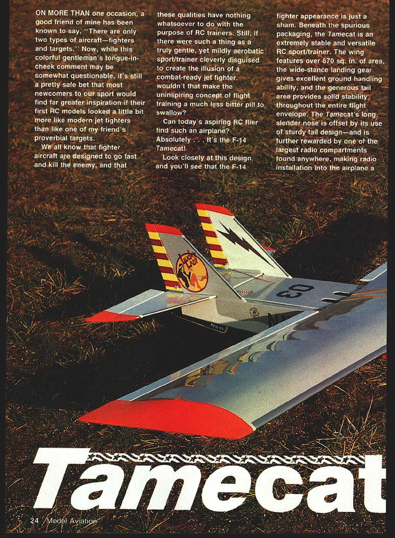
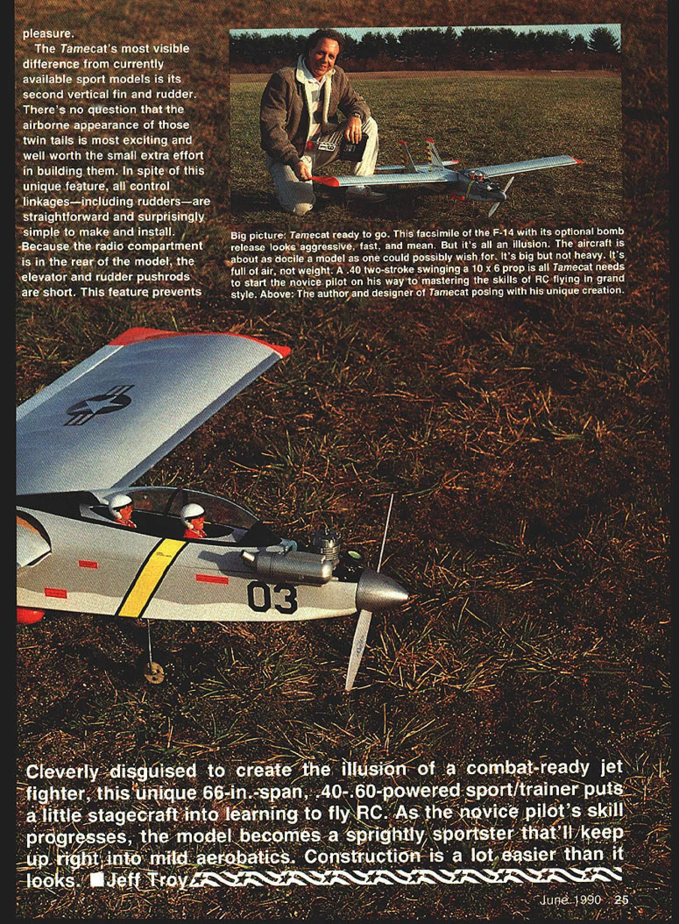
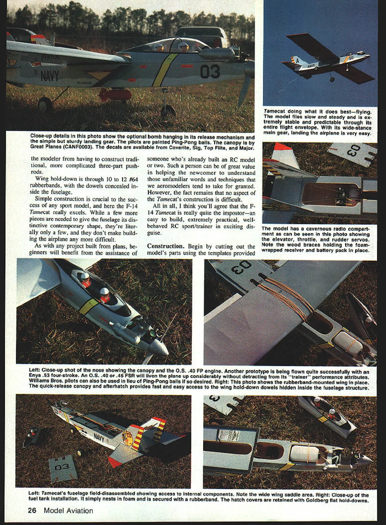
NO OCR TEXT NO OCR TEXT Close-up aeiaiis tnis pnoto show optional bomb hanging Its release mechanism simple sturdy landing gear pilots painted Ping-Pang balls canopy Great Planes CANFOOO3 decals available Coverite Sig Top Flite Major modeler having construct tradi tional complicated three-part pushrods Wing hold-down through 10 12 #64 rubberbands dowels concealed side fuselage Simple construction crucial suc cess sport model F-14 Tamecat really excels few pieces needed give fuselage its dis tinctive contemporary shape theyre liter ally few dont make build ing airplane difficult As project built plans ginners will benefit assistance someone whos already built RC model two Such person can great value helping newcomer understand unfamiliar words techniques aeromodelers tend take granted However fact remains no aspect Tamecats construction difficult think youll agree F14 Tamecat really quite impostoran easy build extremely practical wellbehaved RC sport/trainer exciting dis guise Tamecat doing what does bestflying model flies slow steady ex tremely stable predictable through Its entire flight envelope its wide-stance main gear landing airplane very easy fle model has cavernous radio compart ment can seen photo showing elevator throttle rudder servos Construction Begin cutting out Note wood braces holding foammodels parts using templates provided wrapped receiver battery pack place 26 Model Aviation Left Close-up shot nose showing canopy 05 40 FP engine Another prototype being flown quite successfully Enya 53 four-stroke An 0S 40 45 FSR will liven plane up considerably detracting its trainer performance attributes Williams Bros pilots can also used lieu Ping-Pong balls desired Right photo shows rubberband-mounted wing place quick-release canopy afterhatch provides fast easy access wing hold-down dowels hidden Inside fuselage structure Left Tamecats fuselage field-disassembiea snowing access internal components Note wide wing saddle area Right Close-up fuel tank installation simply nests foam secured rubberband hatch covers retained Goldberg flat hold-downs NO OCR TEXT Construction - NDOFR mis bulkhead F2 nose gear mount already installed being positioned fuselage begins upside down adding bulkheads fuselage crutch Make sure face piece correct direction install triangle helps get things aligned properly right start Kit parts before beginning le box construction fuselage moves along quite rapidly bulkheads installed right side its doublers already place joined crutch TE P ATE i-op c FRO T S __ -r ETOTAT -PICKUP A150 \ ---F FORM NOSE PA RINO FROM /2 BALSA K I PING F cFNPG OS 40 PP SHCS NI o0CO ---I I13/8 8-I4z FJE AK z1 21/4F-SPINNER ENGINE MTI/4A TO SUITFDAM5 ENGINE ST W plans Mark part numbers inside outline piece soft lead pen cii Cut parts slightly larger out lines use sanding tools bring final shapes will ensure parts fit together properly assem bled Whenever sticks cut try cut longer ones first way mistake made can usually use incorrectly cut stick shorter pieces As other parts cut sticks slightly 28 Model Aviation main landing gear block cut ma Inc almost complete fuselage still upside down shows simple construction ple oak Theres plenty strength bottom being sanded smooth accept 1A-in balsa bottom sheeting keep structure make sure its firmly glued catching edges wood its being sanded keep sanding bar 450 angle Full-Size Plans AvailableSee Page 204 y AI 1/4I VTh KiNGE3F3H ill--F-N MAIN LG LAYOUT 5/H2 MW I———— OPEN OPEN GREAT PLANES CANOPY CANFOCO C4BALANCE POINT IN AHEAD OF SPAREND ANDREAR VIEW COWL LINEThNO 4 SCRFW~VSERVO RAILS 5/B DOWELS7k IC~ OPTIONALPF4WRAP RECEIVER BELEVATOR BOMB SERVO UNT ON LITEPLY5/32MWBATTERY PACKTHROTTLE IN FOAM RUBBERRUDDEP OUBLE SIDED TAPEF-14 TAMECAT OPTIONAL VORTAC BOMBWHEELSDESIGNED BY JEFF TROY AND RELEASE SHOWN DRAWN BY JOHN HUNTON 19B9 SPAN 6Bn LENGTH-49/2n ~ENGINE- 40-50 2STR46-BI 4STRPLATE Irn also yield satisfactory results oversize block sand final fit Tape plans flat surface will ac cept pins easily use hollow-core door Horizontal stabilizer elevator Pin cover waxed paper pre- 1A x 1-in trailing edge place fit vent models structures becoming glue two x 1-in center ribs Add stuck plans build S-l center ribs Cut fit leadThe prototype Tamecat models built ing edges tips x -in balsa entirely Pacer Technologys Zap-A- glue pin place Add six Gap CyA cyanoacrylate glue Loctite /8 x A-in balsa stick ribs complete ba slow-setting epoxy used nylon sic stabilizer construction hinges use recommend Use sanding block fitted #100 pafine adhesives other similar products will per sand face back stab June 1990 29 canopy frame being fitted fuselage photo Note wax paper between two structures keep sticking together during construction process Positioning Goldberg flat hold-downs two front rear used se curing canopy sure allow cowl blocks engine mount locat ing catch-screw positions parts smooth bring outer perimeter its final shape Round tips leading edges leave trailing edge sta bilizer flat Mark location five hinges stab x 2-in balsa elevator cut hinge slots both pieces EJ Linds Digger useful tool task After cutting hinge slots sand eleva tor tips trailing edge round bevel leading edge V shape Fit hinges using no glue make cer tain no binding elevator travels smoothly both directions satisfied remove five hinges set parts aside Vertical stabilizers rudders Tamecats verticals assembled same manner horizontal stab ele vator dont forget make two Pin R-l fin base place Cut fit leading edge trailing edge R-2 tip Complete fin adding two /8 x A-in balsa ribs MOUNT l/8xIA HOWO TO BOT AFTER JOINING WING HAL/ES 11/2 IN ii B IKI AILERON LINKAGE -j 2K 24 HMark hinge locations cut hinge slots both fins both rudders Sand vertical fins rudders same way did stab/elevator Re member rudder leading edges beveled V shape trailiig edges fins should sanded flat 30 Model Aviation II H II canopy hatch process being plankea witn x Ain balsa strips Planking con sidered some lost art fact Its excellent way build curved surface / completed canopy hatch Step-by-step planking instructions contained text procedure quite easy creates strong lightweight structure nose cowiang IS made trom three 1A x 3in pieces soft balsa bottom piece seen photo positioned first tween temporary spacers explained text photo two side pieces have added engine mount removed nose ring has aligned installed will serve guide carving sanding cowling its final configuration structurally complete fuselage tail surfaces installed Its starting look like sleek Navy jet its Intended emulate After careful final sanding #320-grit paper fuselage can paintedbut paint heavy Any lightweight heat-shrink covering like Black Baron Super MonoKate Oracover would save considerable weight look great Full-Size Plans AvailableSee Page 204 /2 SQ LEADING EDGE SAND LE THUS -7LA SAND AILERON TRAILING EDGE ROUND /BxI/2 SUB-LE 4SPARS 3/16 50 /4SoK ADING EDGE S IND TO RIB 3 Cc CUT W2 TO El E THER SIDE OF DC xl U/ WI / [4 ySAND TIP TO ROUNDED S-APE 9 SET TOP SPAR BACF 3/C2 OUT OUT FOR SERVO LEFT WING PANEL -I /4I 1/4I/S F-14 TAMECAT DESIGN BY JEFF TRDY DRAWN BY JDHN HUNTDN Check free movement both rudders hinges temporarily installed satisfied remove hinges set parts aside Wing have limited building area start left wing panel room available minimal amount time may saved building both wing halves same time will describe wing construc tion panels being built time Begin wing construction pinning down x /2-in balsa bottom spar making certain end meets wing center line exactly Keep extra lengths wood tip end wing Cut fit three pieces /16 x 4-in bot June 1990 31 ECAL HINGE ito 1 1 V U-I HINGE r i L1 PLATE 2 shaped nose cowling Model Magic filler being used fix dings dents Its lightweight very easy sand Note drain hole bottom cowling final shape length cowling will vary size type engine used finished engine instaliation canopy hatch removed showing fuel line rout ing OS 40 FP engine Notice cowling has notched needle valve Full-Size Plans Available Page 204 ErZii7 CE EEOCHZ EEOCR raREOC /4 BALSA ____________REREE WA Ca REaC W7 PA Ca aTar WE Ca REOCW9 Ca aaar /8 BASA ] CaEaoa WECa aaASWIOCaEEOCCUE OUTwra Ca EEaC I/S BALSA WriCa EEOC N ITote reatove C/BW4 Ca ROar Nfaoro S-WA N OCeOT 52 9TOO TSr COEROCA TAt CaC CO EEOCWOCCOROWOCaECC WACa EEOCW3 Ca EEOC C/B LCTEPY cr Tear-a TAIa4ECATeraca C torn center sheeting Fit two pieces behind spar piece forward Glue pin sheets place inner edges flush wings centerline Block up front edge forward sheeting / Add A-in-sq trailing edge locating its end accurately centerline Add A-in balsa W-4 tip rib seven /6 balsa W-3 ribs using small trian gle ensure uprightness Glue rib se curely bottom spar trailing edge Add outer W-2 rib over bottom sheeting fit glue / x -in balsa sub-leading edge forward center sheeting noses ribs bot torn sub-leading edge should blocked up % work surface Add triangular W-7 gussets tip rib meets leading trailing edges rear gusset should lie flat wing bottom front gusset should centered back subleading edge Glue x -in balsa top spar place Use S-G spar gauge position spars root back wings centerline will allow wing panels mate correctly joined proper dihedral angle After jop spar glued place add W-a /16 vertical-grained shear web between rib front spars webs should sit lower edges flat bench surfaces must make good contact both upper lower spars Shear webs critical wings strength must glued secure ly Remove pins lift wing panel workbench Trim off excess lengths wood extending beyond W-4 tip rib block sand ends spars trailing edge sub-leading edge flush WA tip rib youve built left panel far repeat prior wing assembly steps de scribed bring right panel same stage construction will ready prepare panels joining left panel pinned down flat block up right panel 3 W-4 tip rib position against left panel Youll need sand mating edges wing parts slightly bring panels gether snugly good fit important work till its right satisfied ap ply glue spars center sheeting lead ing trailing edges join two wing halves making sure right panel still blocked up exactly 3 high tip rib Check fit A-in plywood D-l D-2 dihedral braces glue se curely place Use clamps make certaln tight-fitting assembly dihe dral braces thoroughly dry add last two W-2 ribs cutting two pieces spar notches trimming clear dihedral braces Glue two A-in W-la two W-lb ribs together will thick center ribs bridge upper lower sheeting Cut away portion W-l aileron servo Glue laminated center ribs wing glue two remaining W-la W-lb ribs center section sembly Add remaining /16 vertical balsa shear webs W-l 1 top sheeting support rib Left Wing construction Tamecat borrows Sailplane wing design very lightweight strong photo shows verticalgrain shear webbing place between main spars sure web cut fitted carefully thert firmly glue piace running extra bead glue arpund web Right achieve strong structure its important leading edge sheeting firmly attached ribs running bead along contact surface center leading edge sheeting instailed after wing halves have joined 32 Model Aviation PAr Ca ERaCL-FBt CEEROC Full-Size Plans Available Page 204 I/S L TE0fl -__ P4 p +FT1- ICP2000 LPSL 00 Kp o0PS* P30* 00CLTho 5P6 F3---P5FSoeoooPSo [1_________________________IIP7 55062 I/S PYSS0S L~iii four remaining W-7 gussets wings center section Cut out bottom sheeting aileron servo Glue two 346-sq balsa rear spars notches wing ribs Use sanding block carefully contour top edge sub-leading edges match noses wing ribs im portant since forward wing sheeting will later glued sub-leading edges Take few extra moments see joints between ribs subleading edges blend smoothly Fit top A6 x 4-in balsa front sheeting next sure sand root end sheet its edge matches contour centerline two W-lb center ribs fit good apply glue along entire length top spar top edges four forward ribs center section Line up edge sheet center ribs press place along top spar Use palm hand hold front sheet down onto ribs center section until glue sets Add /16 x 1-in trailing edge sheet ing same manner gluing 3A6-sq rear spars ribs over cen ter section sheeting time Cut fit four pieces sheeting cover wings center section Its best glue set two sheets together sand joint glue pair place sin gle part panel Remove wing assembly bench finish adhering top sheeting rib leading trailing edges Work underside wing bay time Simply run bead CyA along inside structure meets sheeting hold sheet down onto structure until glue dries Remember bay time Because no lower wing sheet ing except center section adhering sheets manner relatively easy task Use sanding block bring over hanging edge rear upper sheeting flush trailing edges front upper sheeting flush sub-leading edges Trim sand ends sheets flush W-4 tip ribs Repin wing down side time glue A-in Lite Ply W-5 wing tips place rear edge tip should pinned down work surface front edge blocked up Add A-in balsa W-6 wing tip trailing edge doublers A-in balsa W-l0 tip fillets %-in balsa W-8 W-9 triangular tip ribs Lift wing again sand noses both wing tips flush faces sub-leading edges Glue two -in-sq balsa leading edges place Smooth wing final shape using block fitted #100 sandpaper Use light touch extreme care Make effort avoid oversanding would al ter shape ribs Holding sand ing block 450 angle spars ribs Left left wing finished ready joined center dihedral break Right After first carefully checking dihedral angle winga joined together gluing firmly clamping %-in ply dihedral braces place until adhesive has completely cured June 1990 33 7 3/4 LONG SAG TSMECAT Left The joined wing just before top sheeting applied Note angled rib side support edge center section sheet ing no bottom sheeting Right stabilizer built flat over plans photo finished stabilizer being sanded smooth jJL Left EJ Linds Digger hinge-slotting tool will take aggravation out otherwise aggravating task Cut small slit #11 X-Acto blade start rock digger back forth press wood slot deep enough use tool remove excess wood hinge pocket thereby avoiding lump wood hinge Inserted Right completed tail structure ready covering stabilizer elevator two rudders fins two landing skids two small triangular inner rudder braces should help keep damaging ribs sand Round leading edges edges wing tips leave trailing edges wing insides wing tips flat mate ailerons Carl Goldberg Models A-in aileron link age works perfectly drive Tamecats strip ailerons Cut nylon tubes length slip over wires bend lat ter 900 point shown plans cut off excess wire Use file deburr ends wires allowing slip holes ailerons easily Very carefully notch bottom wing trailing edges allow aileron link age wires room forward travel Glue aileron tubes position onto wings trailing edges Apply glue very care fully adhering tubes link age wires Use 1 A-in-wide fiberglass tape rein force aileron linkage tubes wrap wings center section joint Mark drill A-in holes leading edges A-in balsa ailerons accept linkage wires cut recess wire aileron Mark cut hinge slots wing ailerons sand aileron trailing edges round bevel leading edges V Leave inside outside ends ailerons flat Trial fit aileron hinges making certain both ailerons can move freely Remove hinges set wing two ai lerons aside Fuselage Begin preparing bulk heads Mark drill correct holes engine mount choice A-in plywood F-l firewall Tamecat flies best using two-stroke engine 40 50 displacement 45-60 four-stroke mount still its correct posi tion use soft pencil trace its outline onto face firewall Insert 4-40 blind nuts behind firewall running bead glue around hold place Drill /6 hole appropriate side firewall red Sullivan #503 throt Continued page 36 34 Model Aviation covered finished elevator twin rudders ready installation Notice covering material has carefully omitted gluing surfaces twin rudders may seem intimidating actually quite simple build attach control link age Isnt really much complex employed single rudder installation TAIBI 0 U U 8-INCH3848 3/8-INCH3845 BALSA WOOD STIcKS 1/1 6-INCH3648 1/161/1606 1/163/3207 1/1601/80811 1/1603/160913 1/160 1/41016 1/16 3/81317 1/16 1/21630 1/16 0 3/42128 3/32-INCH3648 3/323/320811 3/321/80613 3/3203/161015 3/3201/41316 3/3303/81419 3/32 o1/21621 3/32 03/42431 Doable Balsa Wood Prices Spruce Basswood Sticks 1/Ba 1/808113/803/6 1/8 03/1611153/801/2 1/80 1/413173/803/4 1/8 3/81821 1/8 1/21724 1/80 3/42533 3/18-INCH3848 3/16 0 3/161317 3/160 1/41416 3/1603/61621 3/16 1/21825 3/1603/42838 1/4-INCH3848 1/4 o 1/41621 1/4 3181825 1/40 1/22129 1/403/43142 6/18-INCH3848 5/16 5/162027 5/18 3/82230 5/160 1/22736 5/16 3/43852 2737 3041 4460 1/2-INCH3848 1/20 1/23749 1/2 o 3/45270 TRIANGULAR CUT BALSA 1/4o 1/40 3624 3/803/803629 1/2o1/2o3637 3/4o3/4o3647 10103661 BALSA PLANKS 3/403036178 1o2o36164 1o3o36230 104036303 202036230 2o3o36329 204036464 303036490 3o4o36680 BALSA SHEETS 1-INCH3648 1/16 1 3/32 0 1 1/80 1 3/180 1 1/40 1 3/8 1/20 1 2-INCH 1/3202 1/1602 3/32 2 1/8 2 3/16 02 1/4 2 3/8 o 2 1/2 o 2 2736 3040 3344 3749 4157 5372 6588 3848 3040 3646 4154 46 60 54 72 6384 77103 113150 3-INCH3888 1/32034053 1/160343 58 3/32 0 35270 1/8036080 3/16 037285 1/40384112 5/1603103134 3/803120180 1/3o3150 200 4-INCH3848 1/32o485 87 1/160473101 3/320482109 1/80485126 3/1804114151 1/404131183 3/804182271 1/304219325 1/4o6o1274 1/40120 12146 1/4 012024293 1/4 012048585 3/80120 12180 3/8 012024380 3/8 a12048720 1/2 0 120 12202 1/2 0 12024405 1/2012048808 LITE PLYWOOD 1/8o12o1281 1/80 12024122 1/8 12 48244 AIRCRAFT BIRCH PLYWOOD 1/64012012182 1/84 12 0 24384 1/84012048728 1/840480480912 1/32801280 1/3212012118 1/32 12 0 24237 1/32 12 0 48473 1/16o6o12 59 1/160120 12117 1/160 12024234 1/180 12048468 3/320601291 3/32o12o12181 3/32012024362 3/32 12 0 48723 1/808012ISO 1/8o12o12188 1/80 12024387 TAPERED TRAILING 1/8012048784 EDGE 36 48 3/18060 12 741/80 1/22230 3/16 120 12 148 3/1603/42840 3/16012024 283 1/401 55 3/160 12o 48585 5/160 1/4461 3/8 0 15272 * OPEN TO THE PUBLIC * Superior Aircraft Materials 12020-G Centralia iian Gardens California 90716 865-3220 Handling Charge -$500 S3O0 COD mum Order $2000 plus UPS accept Personal checks COD fornia Residents add BVa% Sales Tax tie linkage guide tube Glue two A-in Lite Ply F-2 bulkheads gether drill /l6 hole throttle pushrod tube four A-in holes Carl Gold berg nose gear bearing mounting bolts nose gear bearing should installed back bulkhead time Add A-in Lite Ply F-3A doubler rear A-in Lite Ply bulkhead F-3 Drill two 5/4 holes wing hold-down dowels two /16 holes throttle nose gear pushrod tubes guide tube nose gear must lo cated side fuselage opposite throt tle guide tube Add two A-in Lite Ply F-5A doublers front side A-in Lite Ply F-5 bulkhead Drill two s wing dowels two /I6 holes throttle nose gear pushrod tubes Prepare A-in Lite Ply fuselage crutch scoring top crutch several light passes razor knife just behind loca tion bulkhead F-6 completely across en tire width piece Make effort cut approximately halfway through crutch out slicing way through Scoring allows rear crutch bent downward between F-6 F-7 later step Glue F-2 A-in Lite Ply fuselage crutch sure nose gear bearing facing rearward Use small triangle ensure bulkhead glued 900 crutch same manner add F-3 doubler facing rear add F-5 its doubler facing ward installing F-3 F-5 fuselage crutch will need held down onto tops bulkheads until glue dries en sure angle fuselage top will match wings dihedral Finally install F-6 Note firewall rear bulkhead F-7 installed until later Build rear fuselage sides being sure make both right left two rights two lefts Begin gluing A-in Lite Ply R-D dou blers A-in balsa R-S rear fuselage sides Two A-in Lite Ply LL LR landing gear dou blers LC retaining plate added side assembliestwo LLs left side two LRs right Glue rear fuselage sides crutch bulkheads F-5 F-6 sure pieces mate together tightly scored line F6 bring rear crutch down mates sides rear crutch properly aligned sides add bulkhead F7 glue tail joints securely Trial fit forward A-in Lite Ply F-S fuse lage sides notchea F-5 along front crutch Tuck tabs F-2 F-3 slots fuselage sides After sembly procedure understood glue sides place securely F-2 through F-5 Using no glue trial fit A-in ply firewall forward end crutch Dont forget blind nuts must face rear model forward sides will need pulled tightly firewall latter must tilted slightly match angle sides youre satisfied fit procedure glue firewall securely Add two lengths balsa triangle stock standing upright between back firewall forward fuselage sides will necessary sand triangle stock slightly match angle firewall sides same manner install two additional pieces 4 -in triangle stock behind bulkhead F2 RADIO SOUTH Th AUTHORIZED SERVICE CENTER Call Tony StIlIman Ken Dudley custom work competItion needs etock complete hobby Hne specIalIzing competItion accessorieselI dlacounted prices WE STOCK FUTABA JR & ACE RADIOS & ACCESS YS & OS ENGINES HATORI PIPES& HEADERS AND MUCH MORE!! NEW TOLL FREE ORDER LINE 1-800-962-7802 orders please Featuring fast service qualified peepie YA# latest equipment including SPECTRUMANALYZER Orders COD e VISA MC ~rices subject Change notice 9003 N Davis Hwy Pensacola FL 32514 FREQUENCY CONVERSIONS AMA Frequency Committee Approved mw7 LANLI We stock Futaba IR radios YS engines parts Hatori headers pipes Repair Heli Sets Gyros repair information 904 478-6745 36 Model Aviation A Glue Y4 -in hardwood landing gear block place between rear sides over notches LL-LC LR-LC along bulkhead F-5 Gently spread fuselage rear sides apart al lowing slide F-4 A-in Lite Ply bulk head notches forward fuselage sides its seated properly glue F-4 place Glue four /8-in Lite Ply H-D hatch corner dou blers underside crutch Install two 5/16-dia wing hold-down dowels Working open bottom model glue T-S tank floor spacer inside fuselage side fuel tank compartment Add /8-in Lite Ply T-F tank floor followed two A-in triangle strip supports side Use sanding block over entire bottom fuselage making sure its flattened enough accept /8-in balsa bottom sheeting Glue rear sheeting first starting F-4 working toward rear add front bottom sheet ing F-4 forward Trim sand bottom sheeting flush sides firewall F7 Use straight pin through bottom sheeting find slot gear wires hardwood landing gear block cut bottom sheeting away slot Use %2 drill bit drill two holes through block main gear wires Angle bit carefully drill down through block slots wires LL LR doublers Use straight pin method front bottom sheeting locate hole nylon nose gear bearing Drill %2 hole through sheeting nose gear Fit two A-in Lite Ply I-C intake covers top bottom edges should sanded angle allowing fit snugly between bottom sheeting fuselage crutch Glue covers place sand outer edges flush rear fuselage sides Round bottom back edges two A-in balsa R-4 tall skids leave edges will glued fuselage flat Set skids aside Sand edges radio compartment cover round tape cover over radio hatch Drill / hole corner cover through crutch through four hatch corner doublers Screw cover down #4 sheet metal screws remove screws set hatch cover aside Put few drops glue screw hole crutch glue thoroughly dry screw four #4 hatch screws back fuse lage remove procedure hard ens thieads wood keep stripping access radio compartment needed Begin canopy assembly laying piece waxed paper over top forward fuselage area Pin A-in Lite Ply canopy assembly floor place top crutch Glue three A-in Lite Ply bulkheads floor Add three A-in Lite Ply C-D doublers holddown screws C-2 front CA rear bulk heads Install three Carl Goldberg Models flat nylon hold-downs onto canopy bulkheads screw shoulder screws firewall F-3 bulkhead Position two forward holddowns A6 outside outline drew firewall earlier may look intimidating actually easi est way sheet canopy assembly planking strips Its really quite simple once get started Use x A-in balsa strips plank canopy area Start fitting first plank Continued page 116 SPORT/PATTERN FLYING FOR ENGINE OR MOTOR SIMPLE TO BUILD TO FLY DESIGNS Featuring extensive pre fabrication including pre cut fuse lage sides tail feathers accurately die machine cut parts HAMMER 20 Pocket size pattern ship 20-30 engines 25 size electric motors Wing span 50 400 sq area 3h-4 lbs flying weight Symmet rical airfoil tapered wing generous side area superb perf mance Has unique simplicity design quick accurate con struction 28 KITS TO CHOOSE FROM IIAVEY675 TOWER LANE YSTEMSWEST CHESTER PA 19380 ORPORATION 215-430-8645 June 1990 37 HAMMER 40 Big brother Hammer 20 attributes- plus larger size wing span 60 620 sq area 451/2 lbs flying weight 35-45 two-cycle 40-60 four-cycle engines 40 size motors Does pattern manuevers can still fly like docile trainer CESSNA 150 real pretty sport scale copy famous trainer 20-30 twocycle 30-40 four-cycle engines 25 size electric motors Wing span 50s 410 sq area 3h-4 lbs flying weight semi-symmetrical airfoil optional flaps wide speed range realistic performance Tamecat/Troy Continued page 37 left side inch behind C-4 rear bulkhead about inch front C-2 ward bulkhead Make certain plank lies flat fuselage crutch against canopy assem bly floor Add identical plank right side Sand slight bevel along edge two planks fit right left above previous ones After first six eight planks place remove pins lift canopy assembly fuselage Remove waxed paper place assembly back fuselage time see good ajob youve done install ing nylon hold-downs Does canopy sembly snap off firmly doesnt make adjustments now Finish planking rest canopy assembly adding right left plank turn keep pressure structure edge succeeding plank should beveled fit angle previous Youll notice remaining planks must made progressively longer rear last ones extend about four inches rearward past C-4 over wing saddle area last two planks will need cut shape before fitting Sand surface fully planked canopy sembly rounded shape blending planks other Trim ends planks front rear completed assembly using paper templates plan Remove sembly fuselage set aside Temporarily install chosen engine mount using 4-40 bolts through mount blind nuts previously installed firewall Tack glue three pieces /16 scrap balsa onto backplate 2 A-in spinner Tack glue /8-in Lite Ply nose ring scraps Make sure backplate nose ring line up Put backplate engine nose ring facing firewall nose made three pieces n soft balsa cut length longer distance between firewall nose ring length will vary according engine selec tion sanded beveled shape front rear fit snugly place between fire wall nose ring Size bottom nose piece drawing line down its center front back Measure mark center 1 rear 3A side front draw line connecting marks front rear Cut excess balsa off along lines glue nose bottom place centered side side between firewall nose ring Engine Vibration Article Corrections article authored George F Abbott May 1990 issue beginning page 53 suffered few lines type being lost pasteup process second full par agraph third column page 56 should have read follows Currently market least two-cylinder model engine cylin ders arranged V Assuming gle between cylinders 90 degrees such engine will primary secondary balance Also available op TOC BDC posed twin-cylinder engine singlethrow crankshaft pistons both move same directionan arrange ment course offers no vibration ad vantage error formula shown Fig 4 should follows Fc w2 rN2 addition Fig 3C Fig 3D acci dentally ommitted shown regret errorsEditor TOC I Ap 109Q027003bO III crank angle 0 Ap C con e C -2ITR FIG 3C PISTON ACCELERAT ON TDC BDC TOC I Fp IO9Q0180270039 IIII crank angle 0 FIG 3D VIBRATION FORCES DUE TO PISTON ACCELERATION Fp C cos 0 Mp piston C 2R two side nose pieces glued place point necessary make cutout side nose block needle valve Drill A-in hole bottom block draining engine compartment Carefully remove spinner backplate A6 balsa scraps nose ring Remove engine mount Use sanding block contour side bot tom blocks transition smoothly rectan gular shape fuselage rounded lines nose ring careful alter round shape nose ring sand Sand top edges side blocks flush top fuselage crutch Carefully sand entire fuselage assembly rounding off corners leaving top edges square Finishing Use Model Magic filler doctor ill-fitting areas wing fuselage tail canopy assembly Sand repaired areas after filler dries smooth components thor oughly #320 sandpaper part model will contact covering material smooth both sight touch Tamecat should ready its final finish Pick authentic Tomcat scheme turns use iron-on film duplicate Any good-quality film covering will suit model nicely fuselage may painted consid erable weight can saved stick plas tic films Coverites Black Baron Top Flites Super MonoKote Hobby Lobbys Oracover have used prototype models good results Cover models component parts sep arately glue finished parts together after ward Make sure dont cover over gluing areas Glue joints must always wood-to-wood never film-to-wood film-to-film some ar eas will find easier cut material away glue joints after covering Once covering task complete epoxy nylon hinges ailerons rudders eleva tor has thoroughly cured install flying surfaces wing vertical fins stabilizer using epoxy again Install nylon con trol horns rudders elevator Glue stabilizer onto rear fuselage Glue two vertical fins Onto stabilizer slots top fuselage Note vertical fins also glued inboard sides fuselage Finally glue A-in trian gle braces against stabilizer vertical fins inboard sides Remove two thin strips covering along rear edges fuselage bottom glue 4 tail skid side bottom Stars-and-bars decals additional graphics available Coverite Sig Manufacturing Top Flite Models Major Decals clear molded canopy #CANFOOO3 Great Planes Model Manufacturing Company can use pair Williams Bros jet fighter pilots simply glue pair painted Ping-Pong balls un der lid Form install main gears Use -in ny Ion straps hold place Install nose gear using steering arm supplied Goldberg Nose Gear set Mount wheels using Y32 collars add engine mount engine fuel tank Line perimeter wing saddle area fuselage foam-backed tape keep out fuel Radio installation Install Sullivan #503 throttle nose gear pushrod guide tubes Use two /8-in Lite Ply P-B pushrod braces along Continued page 119 116 Model Aviation tube help line up nose gear arm rudder servo Drill /l6 hole brace slide over tube glue fuselage crutch other fuselage bottom Trim ends both tubes extend beyond bulkheads F-5 F-3 firewall Glue forward 34-in-sq maple servo rail place Note locations rudder elevator throttle servos plan rudder throttle servo output arms must line up appropriate pushrod guide tubes Use servo measure spacing location rear servo rail glue place Again use servo locate mark mounting holes three fuselage servos Drill /i pilot holes servo mounting screws rails marks Install three servos fuse lage between rails Complete assembly Sullivan throttle nose gear pushrods Attach pushrods throttle lever nose gear steering arm appropriate servo output arms Make up linkage rods elevator rudders Pushrod wires /i6 X 12-in size available Sullivan Sig Manufacturing Du Bro Products Carl Goldberg Models Thread clevis onto pushrod halfway down threaded end use Goldberg Pushrod Connector Du-Bro EZ Connector Z-bend connect pushrods servo ends Before connecting elevator pushrod slip -in Lite Ply F-6A pushrod guide over After rod connected elevator servo con trol horn glue F-6A pushrod guide F-6 prevent pushrod flexing under flight loads An optional Vortac Manufacturing Bomb Re lease Mechanism exploding bomb installa tion illustrated plan course bomb doesnt actually explode its talcum powder load makes great visual effect bomb hits target exciting feature desired fit parts its installation point radio system least five channels will required bomb release option used Cut slot release mechanism floor fuselage Glue two scraps %-in Lite Ply inside floor mounting screw locations Drill two holes screws mount release mechanism Use doublesided tape mount fifth servo onto piece /8-in Lite Ply scrap glue onto ward fuselage floor Linkage servo release mechanism length radio dial cord nonstretching wire string Cut two holes rear fuselage side radio systems on/off switch charge jack Lo cate devices side model opposite engines exhaust Plug switch elevator servo throttle servo rudder servo ail eron extension cable receiver add sec ond extension cable bomb release servo youve used option Wrap receiver battery pack -in foam rubber install front servos behind bulkhead F-5 Use enough foam prevent components moving about inside fuselage Glue two / x -in spruce servo mounting rails place front rear aileron servo opening bottom wing Drill /16 pilot holes mounting screws mount servo wing Make p aileron pushrods same manner did elevator rudder pushrods Plug aileron servo its extension cable receiver check smooth operation both ailerons Check models control surfaces suffi cient throw correct travel direction surface flight training purposes eleva tor rudders ailerons should set throw irection Nose gear travel should about % in direction Confirm models center-of-gravity empty fuel tank Tamecats nose should tilt down two degrees balanced point exactly inch front wings main spar Make absolutely sure before attempt ing fly Flying what Tamecat does best After suc cessfully completing customary range check taxi out point nose wind apply throttle As airplane reaches flying speed gentle touch up elevator will lift smoothly air As would new model ready make minor corrections models attitude Mostly though just relax enjoy easiest-handling airplanes youll ever have pleasure flying model will go exactly aim displaying its very gentle handling characteristics throttle setting Landings what should expected friendly sport planean extremely long powerdown glide no tendency toward tip stall Just point Tamecat spot runway throt tle back glide onto Add power youre short prepared go around again youre too steep Youll really love model final approach interesting feature Tamecat will teach student use elevator trim efficiently other models air planes need pitch trimming fuel tanks empty Tamecats long nose lets see trim changes little better think youll agree students can benefit greatly extra lesson especially since model teaches gently recommended control throws CG position F-14 Tamecat will re quired maneuvers trainer envelope plus few extras Loops lazy rolls sustained inverted flight stall turns Immelmanns split S pleasure perform model stays right target never gets squirrelly Slow fly bys simply magnificent little aerobatics agility desired just move models center-of-gravity back inch balance model main spar crank up aileron elevator surface throws watch Tamecat run rest pack model can teach very basics yet grow right along flier progresses through mild aerobatics instruction sport/training model meets design goals exceeds mimics jet fighter appearance yet sacrifices friendly flying stability easy building quali ties todays top-notch trainers first time see model air twin rudders long nose will prove well-behaved model can still sport fiercely aggressive image Sure Tamecat resembles supersonic ducted-fan-powered accurately scaled-down F14 Its bluff underneath facade no awkward ugly duckling sport/trainer looks someone might actually want own Just wait until flying buddies check Out ferocious-looking Tamecat prowl target urr-r-r-r-r Radio Technique/Myers Continued page 43 anybody must stop transmitting other hand interfere us have no rightsContinued page 156 UURUI-iA RTANKS & SUPERMUFFLERS ZINGER WOOD PROPS GIANT SCALE R/C PLANS 1IJOO QUADRA RT 1 NEODESHA KS 66757 316325-2821 DEALERS CALL SEND $1 FOR COMPLETE CATALOG June1990 119 AT LAST An Effective High Tech Engine Cleaner R/C Engines Just Bruah & Carbons Gone-Guaranteed ONLY $695 CA rusidenta add 725% tax Clean Engines-Run Cooler-Last Longer Send Check Money OrderTo AIRBORNE HOBBIES 3764 30TH ST SAN DIEGO CA 92104 619543-9703 DEALERS INDUIRES WELCOME Pwcakeet Supe Thco4 PeaqItua4 40. FREE CATALOGf l{sbLzajLeui6a M 468 Cypress Rd. Ocala FL 32672 687-1702
Edition: Model Aviation - 1990/06
Page Numbers: 24, 25, 26, 27, 28, 29, 30, 31, 32, 33, 34, 36, 37, 116, 119
Edition: Model Aviation - 1990/06
Page Numbers: 24, 25, 26, 27, 28, 29, 30, 31, 32, 33, 34, 36, 37, 116, 119
NO OCR TEXT NO OCR TEXT Close-up aeiaiis tnis pnoto show optional bomb hanging Its release mechanism simple sturdy landing gear pilots painted Ping-Pang balls canopy Great Planes CANFOOO3 decals available Coverite Sig Top Flite Major modeler having construct tradi tional complicated three-part pushrods Wing hold-down through 10 12 #64 rubberbands dowels concealed side fuselage Simple construction crucial suc cess sport model F-14 Tamecat really excels few pieces needed give fuselage its dis tinctive contemporary shape theyre liter ally few dont make build ing airplane difficult As project built plans ginners will benefit assistance someone whos already built RC model two Such person can great value helping newcomer understand unfamiliar words techniques aeromodelers tend take granted However fact remains no aspect Tamecats construction difficult think youll agree F14 Tamecat really quite impostoran easy build extremely practical wellbehaved RC sport/trainer exciting dis guise Tamecat doing what does bestflying model flies slow steady ex tremely stable predictable through Its entire flight envelope its wide-stance main gear landing airplane very easy fle model has cavernous radio compart ment can seen photo showing elevator throttle rudder servos Construction Begin cutting out Note wood braces holding foammodels parts using templates provided wrapped receiver battery pack place 26 Model Aviation Left Close-up shot nose showing canopy 05 40 FP engine Another prototype being flown quite successfully Enya 53 four-stroke An 0S 40 45 FSR will liven plane up considerably detracting its trainer performance attributes Williams Bros pilots can also used lieu Ping-Pong balls desired Right photo shows rubberband-mounted wing place quick-release canopy afterhatch provides fast easy access wing hold-down dowels hidden Inside fuselage structure Left Tamecats fuselage field-disassembiea snowing access internal components Note wide wing saddle area Right Close-up fuel tank installation simply nests foam secured rubberband hatch covers retained Goldberg flat hold-downs NO OCR TEXT Construction - NDOFR mis bulkhead F2 nose gear mount already installed being positioned fuselage begins upside down adding bulkheads fuselage crutch Make sure face piece correct direction install triangle helps get things aligned properly right start Kit parts before beginning le box construction fuselage moves along quite rapidly bulkheads installed right side its doublers already place joined crutch TE P ATE i-op c FRO T S __ -r ETOTAT -PICKUP A150 \ ---F FORM NOSE PA RINO FROM /2 BALSA K I PING F cFNPG OS 40 PP SHCS NI o0CO ---I I13/8 8-I4z FJE AK z1 21/4F-SPINNER ENGINE MTI/4A TO SUITFDAM5 ENGINE ST W plans Mark part numbers inside outline piece soft lead pen cii Cut parts slightly larger out lines use sanding tools bring final shapes will ensure parts fit together properly assem bled Whenever sticks cut try cut longer ones first way mistake made can usually use incorrectly cut stick shorter pieces As other parts cut sticks slightly 28 Model Aviation main landing gear block cut ma Inc almost complete fuselage still upside down shows simple construction ple oak Theres plenty strength bottom being sanded smooth accept 1A-in balsa bottom sheeting keep structure make sure its firmly glued catching edges wood its being sanded keep sanding bar 450 angle Full-Size Plans AvailableSee Page 204 y AI 1/4I VTh KiNGE3F3H ill--F-N MAIN LG LAYOUT 5/H2 MW I———— OPEN OPEN GREAT PLANES CANOPY CANFOCO C4BALANCE POINT IN AHEAD OF SPAREND ANDREAR VIEW COWL LINEThNO 4 SCRFW~VSERVO RAILS 5/B DOWELS7k IC~ OPTIONALPF4WRAP RECEIVER BELEVATOR BOMB SERVO UNT ON LITEPLY5/32MWBATTERY PACKTHROTTLE IN FOAM RUBBERRUDDEP OUBLE SIDED TAPEF-14 TAMECAT OPTIONAL VORTAC BOMBWHEELSDESIGNED BY JEFF TROY AND RELEASE SHOWN DRAWN BY JOHN HUNTON 19B9 SPAN 6Bn LENGTH-49/2n ~ENGINE- 40-50 2STR46-BI 4STRPLATE Irn also yield satisfactory results oversize block sand final fit Tape plans flat surface will ac cept pins easily use hollow-core door Horizontal stabilizer elevator Pin cover waxed paper pre- 1A x 1-in trailing edge place fit vent models structures becoming glue two x 1-in center ribs Add stuck plans build S-l center ribs Cut fit leadThe prototype Tamecat models built ing edges tips x -in balsa entirely Pacer Technologys Zap-A- glue pin place Add six Gap CyA cyanoacrylate glue Loctite /8 x A-in balsa stick ribs complete ba slow-setting epoxy used nylon sic stabilizer construction hinges use recommend Use sanding block fitted #100 pafine adhesives other similar products will per sand face back stab June 1990 29 canopy frame being fitted fuselage photo Note wax paper between two structures keep sticking together during construction process Positioning Goldberg flat hold-downs two front rear used se curing canopy sure allow cowl blocks engine mount locat ing catch-screw positions parts smooth bring outer perimeter its final shape Round tips leading edges leave trailing edge sta bilizer flat Mark location five hinges stab x 2-in balsa elevator cut hinge slots both pieces EJ Linds Digger useful tool task After cutting hinge slots sand eleva tor tips trailing edge round bevel leading edge V shape Fit hinges using no glue make cer tain no binding elevator travels smoothly both directions satisfied remove five hinges set parts aside Vertical stabilizers rudders Tamecats verticals assembled same manner horizontal stab ele vator dont forget make two Pin R-l fin base place Cut fit leading edge trailing edge R-2 tip Complete fin adding two /8 x A-in balsa ribs MOUNT l/8xIA HOWO TO BOT AFTER JOINING WING HAL/ES 11/2 IN ii B IKI AILERON LINKAGE -j 2K 24 HMark hinge locations cut hinge slots both fins both rudders Sand vertical fins rudders same way did stab/elevator Re member rudder leading edges beveled V shape trailiig edges fins should sanded flat 30 Model Aviation II H II canopy hatch process being plankea witn x Ain balsa strips Planking con sidered some lost art fact Its excellent way build curved surface / completed canopy hatch Step-by-step planking instructions contained text procedure quite easy creates strong lightweight structure nose cowiang IS made trom three 1A x 3in pieces soft balsa bottom piece seen photo positioned first tween temporary spacers explained text photo two side pieces have added engine mount removed nose ring has aligned installed will serve guide carving sanding cowling its final configuration structurally complete fuselage tail surfaces installed Its starting look like sleek Navy jet its Intended emulate After careful final sanding #320-grit paper fuselage can paintedbut paint heavy Any lightweight heat-shrink covering like Black Baron Super MonoKate Oracover would save considerable weight look great Full-Size Plans AvailableSee Page 204 /2 SQ LEADING EDGE SAND LE THUS -7LA SAND AILERON TRAILING EDGE ROUND /BxI/2 SUB-LE 4SPARS 3/16 50 /4SoK ADING EDGE S IND TO RIB 3 Cc CUT W2 TO El E THER SIDE OF DC xl U/ WI / [4 ySAND TIP TO ROUNDED S-APE 9 SET TOP SPAR BACF 3/C2 OUT OUT FOR SERVO LEFT WING PANEL -I /4I 1/4I/S F-14 TAMECAT DESIGN BY JEFF TRDY DRAWN BY JDHN HUNTDN Check free movement both rudders hinges temporarily installed satisfied remove hinges set parts aside Wing have limited building area start left wing panel room available minimal amount time may saved building both wing halves same time will describe wing construc tion panels being built time Begin wing construction pinning down x /2-in balsa bottom spar making certain end meets wing center line exactly Keep extra lengths wood tip end wing Cut fit three pieces /16 x 4-in bot June 1990 31 ECAL HINGE ito 1 1 V U-I HINGE r i L1 PLATE 2 shaped nose cowling Model Magic filler being used fix dings dents Its lightweight very easy sand Note drain hole bottom cowling final shape length cowling will vary size type engine used finished engine instaliation canopy hatch removed showing fuel line rout ing OS 40 FP engine Notice cowling has notched needle valve Full-Size Plans Available Page 204 ErZii7 CE EEOCHZ EEOCR raREOC /4 BALSA ____________REREE WA Ca REaC W7 PA Ca aTar WE Ca REOCW9 Ca aaar /8 BASA ] CaEaoa WECa aaASWIOCaEEOCCUE OUTwra Ca EEaC I/S BALSA WriCa EEOC N ITote reatove C/BW4 Ca ROar Nfaoro S-WA N OCeOT 52 9TOO TSr COEROCA TAt CaC CO EEOCWOCCOROWOCaECC WACa EEOCW3 Ca EEOC C/B LCTEPY cr Tear-a TAIa4ECATeraca C torn center sheeting Fit two pieces behind spar piece forward Glue pin sheets place inner edges flush wings centerline Block up front edge forward sheeting / Add A-in-sq trailing edge locating its end accurately centerline Add A-in balsa W-4 tip rib seven /6 balsa W-3 ribs using small trian gle ensure uprightness Glue rib se curely bottom spar trailing edge Add outer W-2 rib over bottom sheeting fit glue / x -in balsa sub-leading edge forward center sheeting noses ribs bot torn sub-leading edge should blocked up % work surface Add triangular W-7 gussets tip rib meets leading trailing edges rear gusset should lie flat wing bottom front gusset should centered back subleading edge Glue x -in balsa top spar place Use S-G spar gauge position spars root back wings centerline will allow wing panels mate correctly joined proper dihedral angle After jop spar glued place add W-a /16 vertical-grained shear web between rib front spars webs should sit lower edges flat bench surfaces must make good contact both upper lower spars Shear webs critical wings strength must glued secure ly Remove pins lift wing panel workbench Trim off excess lengths wood extending beyond W-4 tip rib block sand ends spars trailing edge sub-leading edge flush WA tip rib youve built left panel far repeat prior wing assembly steps de scribed bring right panel same stage construction will ready prepare panels joining left panel pinned down flat block up right panel 3 W-4 tip rib position against left panel Youll need sand mating edges wing parts slightly bring panels gether snugly good fit important work till its right satisfied ap ply glue spars center sheeting lead ing trailing edges join two wing halves making sure right panel still blocked up exactly 3 high tip rib Check fit A-in plywood D-l D-2 dihedral braces glue se curely place Use clamps make certaln tight-fitting assembly dihe dral braces thoroughly dry add last two W-2 ribs cutting two pieces spar notches trimming clear dihedral braces Glue two A-in W-la two W-lb ribs together will thick center ribs bridge upper lower sheeting Cut away portion W-l aileron servo Glue laminated center ribs wing glue two remaining W-la W-lb ribs center section sembly Add remaining /16 vertical balsa shear webs W-l 1 top sheeting support rib Left Wing construction Tamecat borrows Sailplane wing design very lightweight strong photo shows verticalgrain shear webbing place between main spars sure web cut fitted carefully thert firmly glue piace running extra bead glue arpund web Right achieve strong structure its important leading edge sheeting firmly attached ribs running bead along contact surface center leading edge sheeting instailed after wing halves have joined 32 Model Aviation PAr Ca ERaCL-FBt CEEROC Full-Size Plans Available Page 204 I/S L TE0fl -__ P4 p +FT1- ICP2000 LPSL 00 Kp o0PS* P30* 00CLTho 5P6 F3---P5FSoeoooPSo [1_________________________IIP7 55062 I/S PYSS0S L~iii four remaining W-7 gussets wings center section Cut out bottom sheeting aileron servo Glue two 346-sq balsa rear spars notches wing ribs Use sanding block carefully contour top edge sub-leading edges match noses wing ribs im portant since forward wing sheeting will later glued sub-leading edges Take few extra moments see joints between ribs subleading edges blend smoothly Fit top A6 x 4-in balsa front sheeting next sure sand root end sheet its edge matches contour centerline two W-lb center ribs fit good apply glue along entire length top spar top edges four forward ribs center section Line up edge sheet center ribs press place along top spar Use palm hand hold front sheet down onto ribs center section until glue sets Add /16 x 1-in trailing edge sheet ing same manner gluing 3A6-sq rear spars ribs over cen ter section sheeting time Cut fit four pieces sheeting cover wings center section Its best glue set two sheets together sand joint glue pair place sin gle part panel Remove wing assembly bench finish adhering top sheeting rib leading trailing edges Work underside wing bay time Simply run bead CyA along inside structure meets sheeting hold sheet down onto structure until glue dries Remember bay time Because no lower wing sheet ing except center section adhering sheets manner relatively easy task Use sanding block bring over hanging edge rear upper sheeting flush trailing edges front upper sheeting flush sub-leading edges Trim sand ends sheets flush W-4 tip ribs Repin wing down side time glue A-in Lite Ply W-5 wing tips place rear edge tip should pinned down work surface front edge blocked up Add A-in balsa W-6 wing tip trailing edge doublers A-in balsa W-l0 tip fillets %-in balsa W-8 W-9 triangular tip ribs Lift wing again sand noses both wing tips flush faces sub-leading edges Glue two -in-sq balsa leading edges place Smooth wing final shape using block fitted #100 sandpaper Use light touch extreme care Make effort avoid oversanding would al ter shape ribs Holding sand ing block 450 angle spars ribs Left left wing finished ready joined center dihedral break Right After first carefully checking dihedral angle winga joined together gluing firmly clamping %-in ply dihedral braces place until adhesive has completely cured June 1990 33 7 3/4 LONG SAG TSMECAT Left The joined wing just before top sheeting applied Note angled rib side support edge center section sheet ing no bottom sheeting Right stabilizer built flat over plans photo finished stabilizer being sanded smooth jJL Left EJ Linds Digger hinge-slotting tool will take aggravation out otherwise aggravating task Cut small slit #11 X-Acto blade start rock digger back forth press wood slot deep enough use tool remove excess wood hinge pocket thereby avoiding lump wood hinge Inserted Right completed tail structure ready covering stabilizer elevator two rudders fins two landing skids two small triangular inner rudder braces should help keep damaging ribs sand Round leading edges edges wing tips leave trailing edges wing insides wing tips flat mate ailerons Carl Goldberg Models A-in aileron link age works perfectly drive Tamecats strip ailerons Cut nylon tubes length slip over wires bend lat ter 900 point shown plans cut off excess wire Use file deburr ends wires allowing slip holes ailerons easily Very carefully notch bottom wing trailing edges allow aileron link age wires room forward travel Glue aileron tubes position onto wings trailing edges Apply glue very care fully adhering tubes link age wires Use 1 A-in-wide fiberglass tape rein force aileron linkage tubes wrap wings center section joint Mark drill A-in holes leading edges A-in balsa ailerons accept linkage wires cut recess wire aileron Mark cut hinge slots wing ailerons sand aileron trailing edges round bevel leading edges V Leave inside outside ends ailerons flat Trial fit aileron hinges making certain both ailerons can move freely Remove hinges set wing two ai lerons aside Fuselage Begin preparing bulk heads Mark drill correct holes engine mount choice A-in plywood F-l firewall Tamecat flies best using two-stroke engine 40 50 displacement 45-60 four-stroke mount still its correct posi tion use soft pencil trace its outline onto face firewall Insert 4-40 blind nuts behind firewall running bead glue around hold place Drill /6 hole appropriate side firewall red Sullivan #503 throt Continued page 36 34 Model Aviation covered finished elevator twin rudders ready installation Notice covering material has carefully omitted gluing surfaces twin rudders may seem intimidating actually quite simple build attach control link age Isnt really much complex employed single rudder installation TAIBI 0 U U 8-INCH3848 3/8-INCH3845 BALSA WOOD STIcKS 1/1 6-INCH3648 1/161/1606 1/163/3207 1/1601/80811 1/1603/160913 1/160 1/41016 1/16 3/81317 1/16 1/21630 1/16 0 3/42128 3/32-INCH3648 3/323/320811 3/321/80613 3/3203/161015 3/3201/41316 3/3303/81419 3/32 o1/21621 3/32 03/42431 Doable Balsa Wood Prices Spruce Basswood Sticks 1/Ba 1/808113/803/6 1/8 03/1611153/801/2 1/80 1/413173/803/4 1/8 3/81821 1/8 1/21724 1/80 3/42533 3/18-INCH3848 3/16 0 3/161317 3/160 1/41416 3/1603/61621 3/16 1/21825 3/1603/42838 1/4-INCH3848 1/4 o 1/41621 1/4 3181825 1/40 1/22129 1/403/43142 6/18-INCH3848 5/16 5/162027 5/18 3/82230 5/160 1/22736 5/16 3/43852 2737 3041 4460 1/2-INCH3848 1/20 1/23749 1/2 o 3/45270 TRIANGULAR CUT BALSA 1/4o 1/40 3624 3/803/803629 1/2o1/2o3637 3/4o3/4o3647 10103661 BALSA PLANKS 3/403036178 1o2o36164 1o3o36230 104036303 202036230 2o3o36329 204036464 303036490 3o4o36680 BALSA SHEETS 1-INCH3648 1/16 1 3/32 0 1 1/80 1 3/180 1 1/40 1 3/8 1/20 1 2-INCH 1/3202 1/1602 3/32 2 1/8 2 3/16 02 1/4 2 3/8 o 2 1/2 o 2 2736 3040 3344 3749 4157 5372 6588 3848 3040 3646 4154 46 60 54 72 6384 77103 113150 3-INCH3888 1/32034053 1/160343 58 3/32 0 35270 1/8036080 3/16 037285 1/40384112 5/1603103134 3/803120180 1/3o3150 200 4-INCH3848 1/32o485 87 1/160473101 3/320482109 1/80485126 3/1804114151 1/404131183 3/804182271 1/304219325 1/4o6o1274 1/40120 12146 1/4 012024293 1/4 012048585 3/80120 12180 3/8 012024380 3/8 a12048720 1/2 0 120 12202 1/2 0 12024405 1/2012048808 LITE PLYWOOD 1/8o12o1281 1/80 12024122 1/8 12 48244 AIRCRAFT BIRCH PLYWOOD 1/64012012182 1/84 12 0 24384 1/84012048728 1/840480480912 1/32801280 1/3212012118 1/32 12 0 24237 1/32 12 0 48473 1/16o6o12 59 1/160120 12117 1/160 12024234 1/180 12048468 3/320601291 3/32o12o12181 3/32012024362 3/32 12 0 48723 1/808012ISO 1/8o12o12188 1/80 12024387 TAPERED TRAILING 1/8012048784 EDGE 36 48 3/18060 12 741/80 1/22230 3/16 120 12 148 3/1603/42840 3/16012024 283 1/401 55 3/160 12o 48585 5/160 1/4461 3/8 0 15272 * OPEN TO THE PUBLIC * Superior Aircraft Materials 12020-G Centralia iian Gardens California 90716 865-3220 Handling Charge -$500 S3O0 COD mum Order $2000 plus UPS accept Personal checks COD fornia Residents add BVa% Sales Tax tie linkage guide tube Glue two A-in Lite Ply F-2 bulkheads gether drill /l6 hole throttle pushrod tube four A-in holes Carl Gold berg nose gear bearing mounting bolts nose gear bearing should installed back bulkhead time Add A-in Lite Ply F-3A doubler rear A-in Lite Ply bulkhead F-3 Drill two 5/4 holes wing hold-down dowels two /16 holes throttle nose gear pushrod tubes guide tube nose gear must lo cated side fuselage opposite throt tle guide tube Add two A-in Lite Ply F-5A doublers front side A-in Lite Ply F-5 bulkhead Drill two s wing dowels two /I6 holes throttle nose gear pushrod tubes Prepare A-in Lite Ply fuselage crutch scoring top crutch several light passes razor knife just behind loca tion bulkhead F-6 completely across en tire width piece Make effort cut approximately halfway through crutch out slicing way through Scoring allows rear crutch bent downward between F-6 F-7 later step Glue F-2 A-in Lite Ply fuselage crutch sure nose gear bearing facing rearward Use small triangle ensure bulkhead glued 900 crutch same manner add F-3 doubler facing rear add F-5 its doubler facing ward installing F-3 F-5 fuselage crutch will need held down onto tops bulkheads until glue dries en sure angle fuselage top will match wings dihedral Finally install F-6 Note firewall rear bulkhead F-7 installed until later Build rear fuselage sides being sure make both right left two rights two lefts Begin gluing A-in Lite Ply R-D dou blers A-in balsa R-S rear fuselage sides Two A-in Lite Ply LL LR landing gear dou blers LC retaining plate added side assembliestwo LLs left side two LRs right Glue rear fuselage sides crutch bulkheads F-5 F-6 sure pieces mate together tightly scored line F6 bring rear crutch down mates sides rear crutch properly aligned sides add bulkhead F7 glue tail joints securely Trial fit forward A-in Lite Ply F-S fuse lage sides notchea F-5 along front crutch Tuck tabs F-2 F-3 slots fuselage sides After sembly procedure understood glue sides place securely F-2 through F-5 Using no glue trial fit A-in ply firewall forward end crutch Dont forget blind nuts must face rear model forward sides will need pulled tightly firewall latter must tilted slightly match angle sides youre satisfied fit procedure glue firewall securely Add two lengths balsa triangle stock standing upright between back firewall forward fuselage sides will necessary sand triangle stock slightly match angle firewall sides same manner install two additional pieces 4 -in triangle stock behind bulkhead F2 RADIO SOUTH Th AUTHORIZED SERVICE CENTER Call Tony StIlIman Ken Dudley custom work competItion needs etock complete hobby Hne specIalIzing competItion accessorieselI dlacounted prices WE STOCK FUTABA JR & ACE RADIOS & ACCESS YS & OS ENGINES HATORI PIPES& HEADERS AND MUCH MORE!! NEW TOLL FREE ORDER LINE 1-800-962-7802 orders please Featuring fast service qualified peepie YA# latest equipment including SPECTRUMANALYZER Orders COD e VISA MC ~rices subject Change notice 9003 N Davis Hwy Pensacola FL 32514 FREQUENCY CONVERSIONS AMA Frequency Committee Approved mw7 LANLI We stock Futaba IR radios YS engines parts Hatori headers pipes Repair Heli Sets Gyros repair information 904 478-6745 36 Model Aviation A Glue Y4 -in hardwood landing gear block place between rear sides over notches LL-LC LR-LC along bulkhead F-5 Gently spread fuselage rear sides apart al lowing slide F-4 A-in Lite Ply bulk head notches forward fuselage sides its seated properly glue F-4 place Glue four /8-in Lite Ply H-D hatch corner dou blers underside crutch Install two 5/16-dia wing hold-down dowels Working open bottom model glue T-S tank floor spacer inside fuselage side fuel tank compartment Add /8-in Lite Ply T-F tank floor followed two A-in triangle strip supports side Use sanding block over entire bottom fuselage making sure its flattened enough accept /8-in balsa bottom sheeting Glue rear sheeting first starting F-4 working toward rear add front bottom sheet ing F-4 forward Trim sand bottom sheeting flush sides firewall F7 Use straight pin through bottom sheeting find slot gear wires hardwood landing gear block cut bottom sheeting away slot Use %2 drill bit drill two holes through block main gear wires Angle bit carefully drill down through block slots wires LL LR doublers Use straight pin method front bottom sheeting locate hole nylon nose gear bearing Drill %2 hole through sheeting nose gear Fit two A-in Lite Ply I-C intake covers top bottom edges should sanded angle allowing fit snugly between bottom sheeting fuselage crutch Glue covers place sand outer edges flush rear fuselage sides Round bottom back edges two A-in balsa R-4 tall skids leave edges will glued fuselage flat Set skids aside Sand edges radio compartment cover round tape cover over radio hatch Drill / hole corner cover through crutch through four hatch corner doublers Screw cover down #4 sheet metal screws remove screws set hatch cover aside Put few drops glue screw hole crutch glue thoroughly dry screw four #4 hatch screws back fuse lage remove procedure hard ens thieads wood keep stripping access radio compartment needed Begin canopy assembly laying piece waxed paper over top forward fuselage area Pin A-in Lite Ply canopy assembly floor place top crutch Glue three A-in Lite Ply bulkheads floor Add three A-in Lite Ply C-D doublers holddown screws C-2 front CA rear bulk heads Install three Carl Goldberg Models flat nylon hold-downs onto canopy bulkheads screw shoulder screws firewall F-3 bulkhead Position two forward holddowns A6 outside outline drew firewall earlier may look intimidating actually easi est way sheet canopy assembly planking strips Its really quite simple once get started Use x A-in balsa strips plank canopy area Start fitting first plank Continued page 116 SPORT/PATTERN FLYING FOR ENGINE OR MOTOR SIMPLE TO BUILD TO FLY DESIGNS Featuring extensive pre fabrication including pre cut fuse lage sides tail feathers accurately die machine cut parts HAMMER 20 Pocket size pattern ship 20-30 engines 25 size electric motors Wing span 50 400 sq area 3h-4 lbs flying weight Symmet rical airfoil tapered wing generous side area superb perf mance Has unique simplicity design quick accurate con struction 28 KITS TO CHOOSE FROM IIAVEY675 TOWER LANE YSTEMSWEST CHESTER PA 19380 ORPORATION 215-430-8645 June 1990 37 HAMMER 40 Big brother Hammer 20 attributes- plus larger size wing span 60 620 sq area 451/2 lbs flying weight 35-45 two-cycle 40-60 four-cycle engines 40 size motors Does pattern manuevers can still fly like docile trainer CESSNA 150 real pretty sport scale copy famous trainer 20-30 twocycle 30-40 four-cycle engines 25 size electric motors Wing span 50s 410 sq area 3h-4 lbs flying weight semi-symmetrical airfoil optional flaps wide speed range realistic performance Tamecat/Troy Continued page 37 left side inch behind C-4 rear bulkhead about inch front C-2 ward bulkhead Make certain plank lies flat fuselage crutch against canopy assem bly floor Add identical plank right side Sand slight bevel along edge two planks fit right left above previous ones After first six eight planks place remove pins lift canopy assembly fuselage Remove waxed paper place assembly back fuselage time see good ajob youve done install ing nylon hold-downs Does canopy sembly snap off firmly doesnt make adjustments now Finish planking rest canopy assembly adding right left plank turn keep pressure structure edge succeeding plank should beveled fit angle previous Youll notice remaining planks must made progressively longer rear last ones extend about four inches rearward past C-4 over wing saddle area last two planks will need cut shape before fitting Sand surface fully planked canopy sembly rounded shape blending planks other Trim ends planks front rear completed assembly using paper templates plan Remove sembly fuselage set aside Temporarily install chosen engine mount using 4-40 bolts through mount blind nuts previously installed firewall Tack glue three pieces /16 scrap balsa onto backplate 2 A-in spinner Tack glue /8-in Lite Ply nose ring scraps Make sure backplate nose ring line up Put backplate engine nose ring facing firewall nose made three pieces n soft balsa cut length longer distance between firewall nose ring length will vary according engine selec tion sanded beveled shape front rear fit snugly place between fire wall nose ring Size bottom nose piece drawing line down its center front back Measure mark center 1 rear 3A side front draw line connecting marks front rear Cut excess balsa off along lines glue nose bottom place centered side side between firewall nose ring Engine Vibration Article Corrections article authored George F Abbott May 1990 issue beginning page 53 suffered few lines type being lost pasteup process second full par agraph third column page 56 should have read follows Currently market least two-cylinder model engine cylin ders arranged V Assuming gle between cylinders 90 degrees such engine will primary secondary balance Also available op TOC BDC posed twin-cylinder engine singlethrow crankshaft pistons both move same directionan arrange ment course offers no vibration ad vantage error formula shown Fig 4 should follows Fc w2 rN2 addition Fig 3C Fig 3D acci dentally ommitted shown regret errorsEditor TOC I Ap 109Q027003bO III crank angle 0 Ap C con e C -2ITR FIG 3C PISTON ACCELERAT ON TDC BDC TOC I Fp IO9Q0180270039 IIII crank angle 0 FIG 3D VIBRATION FORCES DUE TO PISTON ACCELERATION Fp C cos 0 Mp piston C 2R two side nose pieces glued place point necessary make cutout side nose block needle valve Drill A-in hole bottom block draining engine compartment Carefully remove spinner backplate A6 balsa scraps nose ring Remove engine mount Use sanding block contour side bot tom blocks transition smoothly rectan gular shape fuselage rounded lines nose ring careful alter round shape nose ring sand Sand top edges side blocks flush top fuselage crutch Carefully sand entire fuselage assembly rounding off corners leaving top edges square Finishing Use Model Magic filler doctor ill-fitting areas wing fuselage tail canopy assembly Sand repaired areas after filler dries smooth components thor oughly #320 sandpaper part model will contact covering material smooth both sight touch Tamecat should ready its final finish Pick authentic Tomcat scheme turns use iron-on film duplicate Any good-quality film covering will suit model nicely fuselage may painted consid erable weight can saved stick plas tic films Coverites Black Baron Top Flites Super MonoKote Hobby Lobbys Oracover have used prototype models good results Cover models component parts sep arately glue finished parts together after ward Make sure dont cover over gluing areas Glue joints must always wood-to-wood never film-to-wood film-to-film some ar eas will find easier cut material away glue joints after covering Once covering task complete epoxy nylon hinges ailerons rudders eleva tor has thoroughly cured install flying surfaces wing vertical fins stabilizer using epoxy again Install nylon con trol horns rudders elevator Glue stabilizer onto rear fuselage Glue two vertical fins Onto stabilizer slots top fuselage Note vertical fins also glued inboard sides fuselage Finally glue A-in trian gle braces against stabilizer vertical fins inboard sides Remove two thin strips covering along rear edges fuselage bottom glue 4 tail skid side bottom Stars-and-bars decals additional graphics available Coverite Sig Manufacturing Top Flite Models Major Decals clear molded canopy #CANFOOO3 Great Planes Model Manufacturing Company can use pair Williams Bros jet fighter pilots simply glue pair painted Ping-Pong balls un der lid Form install main gears Use -in ny Ion straps hold place Install nose gear using steering arm supplied Goldberg Nose Gear set Mount wheels using Y32 collars add engine mount engine fuel tank Line perimeter wing saddle area fuselage foam-backed tape keep out fuel Radio installation Install Sullivan #503 throttle nose gear pushrod guide tubes Use two /8-in Lite Ply P-B pushrod braces along Continued page 119 116 Model Aviation tube help line up nose gear arm rudder servo Drill /l6 hole brace slide over tube glue fuselage crutch other fuselage bottom Trim ends both tubes extend beyond bulkheads F-5 F-3 firewall Glue forward 34-in-sq maple servo rail place Note locations rudder elevator throttle servos plan rudder throttle servo output arms must line up appropriate pushrod guide tubes Use servo measure spacing location rear servo rail glue place Again use servo locate mark mounting holes three fuselage servos Drill /i pilot holes servo mounting screws rails marks Install three servos fuse lage between rails Complete assembly Sullivan throttle nose gear pushrods Attach pushrods throttle lever nose gear steering arm appropriate servo output arms Make up linkage rods elevator rudders Pushrod wires /i6 X 12-in size available Sullivan Sig Manufacturing Du Bro Products Carl Goldberg Models Thread clevis onto pushrod halfway down threaded end use Goldberg Pushrod Connector Du-Bro EZ Connector Z-bend connect pushrods servo ends Before connecting elevator pushrod slip -in Lite Ply F-6A pushrod guide over After rod connected elevator servo con trol horn glue F-6A pushrod guide F-6 prevent pushrod flexing under flight loads An optional Vortac Manufacturing Bomb Re lease Mechanism exploding bomb installa tion illustrated plan course bomb doesnt actually explode its talcum powder load makes great visual effect bomb hits target exciting feature desired fit parts its installation point radio system least five channels will required bomb release option used Cut slot release mechanism floor fuselage Glue two scraps %-in Lite Ply inside floor mounting screw locations Drill two holes screws mount release mechanism Use doublesided tape mount fifth servo onto piece /8-in Lite Ply scrap glue onto ward fuselage floor Linkage servo release mechanism length radio dial cord nonstretching wire string Cut two holes rear fuselage side radio systems on/off switch charge jack Lo cate devices side model opposite engines exhaust Plug switch elevator servo throttle servo rudder servo ail eron extension cable receiver add sec ond extension cable bomb release servo youve used option Wrap receiver battery pack -in foam rubber install front servos behind bulkhead F-5 Use enough foam prevent components moving about inside fuselage Glue two / x -in spruce servo mounting rails place front rear aileron servo opening bottom wing Drill /16 pilot holes mounting screws mount servo wing Make p aileron pushrods same manner did elevator rudder pushrods Plug aileron servo its extension cable receiver check smooth operation both ailerons Check models control surfaces suffi cient throw correct travel direction surface flight training purposes eleva tor rudders ailerons should set throw irection Nose gear travel should about % in direction Confirm models center-of-gravity empty fuel tank Tamecats nose should tilt down two degrees balanced point exactly inch front wings main spar Make absolutely sure before attempt ing fly Flying what Tamecat does best After suc cessfully completing customary range check taxi out point nose wind apply throttle As airplane reaches flying speed gentle touch up elevator will lift smoothly air As would new model ready make minor corrections models attitude Mostly though just relax enjoy easiest-handling airplanes youll ever have pleasure flying model will go exactly aim displaying its very gentle handling characteristics throttle setting Landings what should expected friendly sport planean extremely long powerdown glide no tendency toward tip stall Just point Tamecat spot runway throt tle back glide onto Add power youre short prepared go around again youre too steep Youll really love model final approach interesting feature Tamecat will teach student use elevator trim efficiently other models air planes need pitch trimming fuel tanks empty Tamecats long nose lets see trim changes little better think youll agree students can benefit greatly extra lesson especially since model teaches gently recommended control throws CG position F-14 Tamecat will re quired maneuvers trainer envelope plus few extras Loops lazy rolls sustained inverted flight stall turns Immelmanns split S pleasure perform model stays right target never gets squirrelly Slow fly bys simply magnificent little aerobatics agility desired just move models center-of-gravity back inch balance model main spar crank up aileron elevator surface throws watch Tamecat run rest pack model can teach very basics yet grow right along flier progresses through mild aerobatics instruction sport/training model meets design goals exceeds mimics jet fighter appearance yet sacrifices friendly flying stability easy building quali ties todays top-notch trainers first time see model air twin rudders long nose will prove well-behaved model can still sport fiercely aggressive image Sure Tamecat resembles supersonic ducted-fan-powered accurately scaled-down F14 Its bluff underneath facade no awkward ugly duckling sport/trainer looks someone might actually want own Just wait until flying buddies check Out ferocious-looking Tamecat prowl target urr-r-r-r-r Radio Technique/Myers Continued page 43 anybody must stop transmitting other hand interfere us have no rightsContinued page 156 UURUI-iA RTANKS & SUPERMUFFLERS ZINGER WOOD PROPS GIANT SCALE R/C PLANS 1IJOO QUADRA RT 1 NEODESHA KS 66757 316325-2821 DEALERS CALL SEND $1 FOR COMPLETE CATALOG June1990 119 AT LAST An Effective High Tech Engine Cleaner R/C Engines Just Bruah & Carbons Gone-Guaranteed ONLY $695 CA rusidenta add 725% tax Clean Engines-Run Cooler-Last Longer Send Check Money OrderTo AIRBORNE HOBBIES 3764 30TH ST SAN DIEGO CA 92104 619543-9703 DEALERS INDUIRES WELCOME Pwcakeet Supe Thco4 PeaqItua4 40. FREE CATALOGf l{sbLzajLeui6a M 468 Cypress Rd. Ocala FL 32672 687-1702
Edition: Model Aviation - 1990/06
Page Numbers: 24, 25, 26, 27, 28, 29, 30, 31, 32, 33, 34, 36, 37, 116, 119
NO OCR TEXT NO OCR TEXT Close-up aeiaiis tnis pnoto show optional bomb hanging Its release mechanism simple sturdy landing gear pilots painted Ping-Pang balls canopy Great Planes CANFOOO3 decals available Coverite Sig Top Flite Major modeler having construct tradi tional complicated three-part pushrods Wing hold-down through 10 12 #64 rubberbands dowels concealed side fuselage Simple construction crucial suc cess sport model F-14 Tamecat really excels few pieces needed give fuselage its dis tinctive contemporary shape theyre liter ally few dont make build ing airplane difficult As project built plans ginners will benefit assistance someone whos already built RC model two Such person can great value helping newcomer understand unfamiliar words techniques aeromodelers tend take granted However fact remains no aspect Tamecats construction difficult think youll agree F14 Tamecat really quite impostoran easy build extremely practical wellbehaved RC sport/trainer exciting dis guise Tamecat doing what does bestflying model flies slow steady ex tremely stable predictable through Its entire flight envelope its wide-stance main gear landing airplane very easy fle model has cavernous radio compart ment can seen photo showing elevator throttle rudder servos Construction Begin cutting out Note wood braces holding foammodels parts using templates provided wrapped receiver battery pack place 26 Model Aviation Left Close-up shot nose showing canopy 05 40 FP engine Another prototype being flown quite successfully Enya 53 four-stroke An 0S 40 45 FSR will liven plane up considerably detracting its trainer performance attributes Williams Bros pilots can also used lieu Ping-Pong balls desired Right photo shows rubberband-mounted wing place quick-release canopy afterhatch provides fast easy access wing hold-down dowels hidden Inside fuselage structure Left Tamecats fuselage field-disassembiea snowing access internal components Note wide wing saddle area Right Close-up fuel tank installation simply nests foam secured rubberband hatch covers retained Goldberg flat hold-downs NO OCR TEXT Construction - NDOFR mis bulkhead F2 nose gear mount already installed being positioned fuselage begins upside down adding bulkheads fuselage crutch Make sure face piece correct direction install triangle helps get things aligned properly right start Kit parts before beginning le box construction fuselage moves along quite rapidly bulkheads installed right side its doublers already place joined crutch TE P ATE i-op c FRO T S __ -r ETOTAT -PICKUP A150 \ ---F FORM NOSE PA RINO FROM /2 BALSA K I PING F cFNPG OS 40 PP SHCS NI o0CO ---I I13/8 8-I4z FJE AK z1 21/4F-SPINNER ENGINE MTI/4A TO SUITFDAM5 ENGINE ST W plans Mark part numbers inside outline piece soft lead pen cii Cut parts slightly larger out lines use sanding tools bring final shapes will ensure parts fit together properly assem bled Whenever sticks cut try cut longer ones first way mistake made can usually use incorrectly cut stick shorter pieces As other parts cut sticks slightly 28 Model Aviation main landing gear block cut ma Inc almost complete fuselage still upside down shows simple construction ple oak Theres plenty strength bottom being sanded smooth accept 1A-in balsa bottom sheeting keep structure make sure its firmly glued catching edges wood its being sanded keep sanding bar 450 angle Full-Size Plans AvailableSee Page 204 y AI 1/4I VTh KiNGE3F3H ill--F-N MAIN LG LAYOUT 5/H2 MW I———— OPEN OPEN GREAT PLANES CANOPY CANFOCO C4BALANCE POINT IN AHEAD OF SPAREND ANDREAR VIEW COWL LINEThNO 4 SCRFW~VSERVO RAILS 5/B DOWELS7k IC~ OPTIONALPF4WRAP RECEIVER BELEVATOR BOMB SERVO UNT ON LITEPLY5/32MWBATTERY PACKTHROTTLE IN FOAM RUBBERRUDDEP OUBLE SIDED TAPEF-14 TAMECAT OPTIONAL VORTAC BOMBWHEELSDESIGNED BY JEFF TROY AND RELEASE SHOWN DRAWN BY JOHN HUNTON 19B9 SPAN 6Bn LENGTH-49/2n ~ENGINE- 40-50 2STR46-BI 4STRPLATE Irn also yield satisfactory results oversize block sand final fit Tape plans flat surface will ac cept pins easily use hollow-core door Horizontal stabilizer elevator Pin cover waxed paper pre- 1A x 1-in trailing edge place fit vent models structures becoming glue two x 1-in center ribs Add stuck plans build S-l center ribs Cut fit leadThe prototype Tamecat models built ing edges tips x -in balsa entirely Pacer Technologys Zap-A- glue pin place Add six Gap CyA cyanoacrylate glue Loctite /8 x A-in balsa stick ribs complete ba slow-setting epoxy used nylon sic stabilizer construction hinges use recommend Use sanding block fitted #100 pafine adhesives other similar products will per sand face back stab June 1990 29 canopy frame being fitted fuselage photo Note wax paper between two structures keep sticking together during construction process Positioning Goldberg flat hold-downs two front rear used se curing canopy sure allow cowl blocks engine mount locat ing catch-screw positions parts smooth bring outer perimeter its final shape Round tips leading edges leave trailing edge sta bilizer flat Mark location five hinges stab x 2-in balsa elevator cut hinge slots both pieces EJ Linds Digger useful tool task After cutting hinge slots sand eleva tor tips trailing edge round bevel leading edge V shape Fit hinges using no glue make cer tain no binding elevator travels smoothly both directions satisfied remove five hinges set parts aside Vertical stabilizers rudders Tamecats verticals assembled same manner horizontal stab ele vator dont forget make two Pin R-l fin base place Cut fit leading edge trailing edge R-2 tip Complete fin adding two /8 x A-in balsa ribs MOUNT l/8xIA HOWO TO BOT AFTER JOINING WING HAL/ES 11/2 IN ii B IKI AILERON LINKAGE -j 2K 24 HMark hinge locations cut hinge slots both fins both rudders Sand vertical fins rudders same way did stab/elevator Re member rudder leading edges beveled V shape trailiig edges fins should sanded flat 30 Model Aviation II H II canopy hatch process being plankea witn x Ain balsa strips Planking con sidered some lost art fact Its excellent way build curved surface / completed canopy hatch Step-by-step planking instructions contained text procedure quite easy creates strong lightweight structure nose cowiang IS made trom three 1A x 3in pieces soft balsa bottom piece seen photo positioned first tween temporary spacers explained text photo two side pieces have added engine mount removed nose ring has aligned installed will serve guide carving sanding cowling its final configuration structurally complete fuselage tail surfaces installed Its starting look like sleek Navy jet its Intended emulate After careful final sanding #320-grit paper fuselage can paintedbut paint heavy Any lightweight heat-shrink covering like Black Baron Super MonoKate Oracover would save considerable weight look great Full-Size Plans AvailableSee Page 204 /2 SQ LEADING EDGE SAND LE THUS -7LA SAND AILERON TRAILING EDGE ROUND /BxI/2 SUB-LE 4SPARS 3/16 50 /4SoK ADING EDGE S IND TO RIB 3 Cc CUT W2 TO El E THER SIDE OF DC xl U/ WI / [4 ySAND TIP TO ROUNDED S-APE 9 SET TOP SPAR BACF 3/C2 OUT OUT FOR SERVO LEFT WING PANEL -I /4I 1/4I/S F-14 TAMECAT DESIGN BY JEFF TRDY DRAWN BY JDHN HUNTDN Check free movement both rudders hinges temporarily installed satisfied remove hinges set parts aside Wing have limited building area start left wing panel room available minimal amount time may saved building both wing halves same time will describe wing construc tion panels being built time Begin wing construction pinning down x /2-in balsa bottom spar making certain end meets wing center line exactly Keep extra lengths wood tip end wing Cut fit three pieces /16 x 4-in bot June 1990 31 ECAL HINGE ito 1 1 V U-I HINGE r i L1 PLATE 2 shaped nose cowling Model Magic filler being used fix dings dents Its lightweight very easy sand Note drain hole bottom cowling final shape length cowling will vary size type engine used finished engine instaliation canopy hatch removed showing fuel line rout ing OS 40 FP engine Notice cowling has notched needle valve Full-Size Plans Available Page 204 ErZii7 CE EEOCHZ EEOCR raREOC /4 BALSA ____________REREE WA Ca REaC W7 PA Ca aTar WE Ca REOCW9 Ca aaar /8 BASA ] CaEaoa WECa aaASWIOCaEEOCCUE OUTwra Ca EEaC I/S BALSA WriCa EEOC N ITote reatove C/BW4 Ca ROar Nfaoro S-WA N OCeOT 52 9TOO TSr COEROCA TAt CaC CO EEOCWOCCOROWOCaECC WACa EEOCW3 Ca EEOC C/B LCTEPY cr Tear-a TAIa4ECATeraca C torn center sheeting Fit two pieces behind spar piece forward Glue pin sheets place inner edges flush wings centerline Block up front edge forward sheeting / Add A-in-sq trailing edge locating its end accurately centerline Add A-in balsa W-4 tip rib seven /6 balsa W-3 ribs using small trian gle ensure uprightness Glue rib se curely bottom spar trailing edge Add outer W-2 rib over bottom sheeting fit glue / x -in balsa sub-leading edge forward center sheeting noses ribs bot torn sub-leading edge should blocked up % work surface Add triangular W-7 gussets tip rib meets leading trailing edges rear gusset should lie flat wing bottom front gusset should centered back subleading edge Glue x -in balsa top spar place Use S-G spar gauge position spars root back wings centerline will allow wing panels mate correctly joined proper dihedral angle After jop spar glued place add W-a /16 vertical-grained shear web between rib front spars webs should sit lower edges flat bench surfaces must make good contact both upper lower spars Shear webs critical wings strength must glued secure ly Remove pins lift wing panel workbench Trim off excess lengths wood extending beyond W-4 tip rib block sand ends spars trailing edge sub-leading edge flush WA tip rib youve built left panel far repeat prior wing assembly steps de scribed bring right panel same stage construction will ready prepare panels joining left panel pinned down flat block up right panel 3 W-4 tip rib position against left panel Youll need sand mating edges wing parts slightly bring panels gether snugly good fit important work till its right satisfied ap ply glue spars center sheeting lead ing trailing edges join two wing halves making sure right panel still blocked up exactly 3 high tip rib Check fit A-in plywood D-l D-2 dihedral braces glue se curely place Use clamps make certaln tight-fitting assembly dihe dral braces thoroughly dry add last two W-2 ribs cutting two pieces spar notches trimming clear dihedral braces Glue two A-in W-la two W-lb ribs together will thick center ribs bridge upper lower sheeting Cut away portion W-l aileron servo Glue laminated center ribs wing glue two remaining W-la W-lb ribs center section sembly Add remaining /16 vertical balsa shear webs W-l 1 top sheeting support rib Left Wing construction Tamecat borrows Sailplane wing design very lightweight strong photo shows verticalgrain shear webbing place between main spars sure web cut fitted carefully thert firmly glue piace running extra bead glue arpund web Right achieve strong structure its important leading edge sheeting firmly attached ribs running bead along contact surface center leading edge sheeting instailed after wing halves have joined 32 Model Aviation PAr Ca ERaCL-FBt CEEROC Full-Size Plans Available Page 204 I/S L TE0fl -__ P4 p +FT1- ICP2000 LPSL 00 Kp o0PS* P30* 00CLTho 5P6 F3---P5FSoeoooPSo [1_________________________IIP7 55062 I/S PYSS0S L~iii four remaining W-7 gussets wings center section Cut out bottom sheeting aileron servo Glue two 346-sq balsa rear spars notches wing ribs Use sanding block carefully contour top edge sub-leading edges match noses wing ribs im portant since forward wing sheeting will later glued sub-leading edges Take few extra moments see joints between ribs subleading edges blend smoothly Fit top A6 x 4-in balsa front sheeting next sure sand root end sheet its edge matches contour centerline two W-lb center ribs fit good apply glue along entire length top spar top edges four forward ribs center section Line up edge sheet center ribs press place along top spar Use palm hand hold front sheet down onto ribs center section until glue sets Add /16 x 1-in trailing edge sheet ing same manner gluing 3A6-sq rear spars ribs over cen ter section sheeting time Cut fit four pieces sheeting cover wings center section Its best glue set two sheets together sand joint glue pair place sin gle part panel Remove wing assembly bench finish adhering top sheeting rib leading trailing edges Work underside wing bay time Simply run bead CyA along inside structure meets sheeting hold sheet down onto structure until glue dries Remember bay time Because no lower wing sheet ing except center section adhering sheets manner relatively easy task Use sanding block bring over hanging edge rear upper sheeting flush trailing edges front upper sheeting flush sub-leading edges Trim sand ends sheets flush W-4 tip ribs Repin wing down side time glue A-in Lite Ply W-5 wing tips place rear edge tip should pinned down work surface front edge blocked up Add A-in balsa W-6 wing tip trailing edge doublers A-in balsa W-l0 tip fillets %-in balsa W-8 W-9 triangular tip ribs Lift wing again sand noses both wing tips flush faces sub-leading edges Glue two -in-sq balsa leading edges place Smooth wing final shape using block fitted #100 sandpaper Use light touch extreme care Make effort avoid oversanding would al ter shape ribs Holding sand ing block 450 angle spars ribs Left left wing finished ready joined center dihedral break Right After first carefully checking dihedral angle winga joined together gluing firmly clamping %-in ply dihedral braces place until adhesive has completely cured June 1990 33 7 3/4 LONG SAG TSMECAT Left The joined wing just before top sheeting applied Note angled rib side support edge center section sheet ing no bottom sheeting Right stabilizer built flat over plans photo finished stabilizer being sanded smooth jJL Left EJ Linds Digger hinge-slotting tool will take aggravation out otherwise aggravating task Cut small slit #11 X-Acto blade start rock digger back forth press wood slot deep enough use tool remove excess wood hinge pocket thereby avoiding lump wood hinge Inserted Right completed tail structure ready covering stabilizer elevator two rudders fins two landing skids two small triangular inner rudder braces should help keep damaging ribs sand Round leading edges edges wing tips leave trailing edges wing insides wing tips flat mate ailerons Carl Goldberg Models A-in aileron link age works perfectly drive Tamecats strip ailerons Cut nylon tubes length slip over wires bend lat ter 900 point shown plans cut off excess wire Use file deburr ends wires allowing slip holes ailerons easily Very carefully notch bottom wing trailing edges allow aileron link age wires room forward travel Glue aileron tubes position onto wings trailing edges Apply glue very care fully adhering tubes link age wires Use 1 A-in-wide fiberglass tape rein force aileron linkage tubes wrap wings center section joint Mark drill A-in holes leading edges A-in balsa ailerons accept linkage wires cut recess wire aileron Mark cut hinge slots wing ailerons sand aileron trailing edges round bevel leading edges V Leave inside outside ends ailerons flat Trial fit aileron hinges making certain both ailerons can move freely Remove hinges set wing two ai lerons aside Fuselage Begin preparing bulk heads Mark drill correct holes engine mount choice A-in plywood F-l firewall Tamecat flies best using two-stroke engine 40 50 displacement 45-60 four-stroke mount still its correct posi tion use soft pencil trace its outline onto face firewall Insert 4-40 blind nuts behind firewall running bead glue around hold place Drill /6 hole appropriate side firewall red Sullivan #503 throt Continued page 36 34 Model Aviation covered finished elevator twin rudders ready installation Notice covering material has carefully omitted gluing surfaces twin rudders may seem intimidating actually quite simple build attach control link age Isnt really much complex employed single rudder installation TAIBI 0 U U 8-INCH3848 3/8-INCH3845 BALSA WOOD STIcKS 1/1 6-INCH3648 1/161/1606 1/163/3207 1/1601/80811 1/1603/160913 1/160 1/41016 1/16 3/81317 1/16 1/21630 1/16 0 3/42128 3/32-INCH3648 3/323/320811 3/321/80613 3/3203/161015 3/3201/41316 3/3303/81419 3/32 o1/21621 3/32 03/42431 Doable Balsa Wood Prices Spruce Basswood Sticks 1/Ba 1/808113/803/6 1/8 03/1611153/801/2 1/80 1/413173/803/4 1/8 3/81821 1/8 1/21724 1/80 3/42533 3/18-INCH3848 3/16 0 3/161317 3/160 1/41416 3/1603/61621 3/16 1/21825 3/1603/42838 1/4-INCH3848 1/4 o 1/41621 1/4 3181825 1/40 1/22129 1/403/43142 6/18-INCH3848 5/16 5/162027 5/18 3/82230 5/160 1/22736 5/16 3/43852 2737 3041 4460 1/2-INCH3848 1/20 1/23749 1/2 o 3/45270 TRIANGULAR CUT BALSA 1/4o 1/40 3624 3/803/803629 1/2o1/2o3637 3/4o3/4o3647 10103661 BALSA PLANKS 3/403036178 1o2o36164 1o3o36230 104036303 202036230 2o3o36329 204036464 303036490 3o4o36680 BALSA SHEETS 1-INCH3648 1/16 1 3/32 0 1 1/80 1 3/180 1 1/40 1 3/8 1/20 1 2-INCH 1/3202 1/1602 3/32 2 1/8 2 3/16 02 1/4 2 3/8 o 2 1/2 o 2 2736 3040 3344 3749 4157 5372 6588 3848 3040 3646 4154 46 60 54 72 6384 77103 113150 3-INCH3888 1/32034053 1/160343 58 3/32 0 35270 1/8036080 3/16 037285 1/40384112 5/1603103134 3/803120180 1/3o3150 200 4-INCH3848 1/32o485 87 1/160473101 3/320482109 1/80485126 3/1804114151 1/404131183 3/804182271 1/304219325 1/4o6o1274 1/40120 12146 1/4 012024293 1/4 012048585 3/80120 12180 3/8 012024380 3/8 a12048720 1/2 0 120 12202 1/2 0 12024405 1/2012048808 LITE PLYWOOD 1/8o12o1281 1/80 12024122 1/8 12 48244 AIRCRAFT BIRCH PLYWOOD 1/64012012182 1/84 12 0 24384 1/84012048728 1/840480480912 1/32801280 1/3212012118 1/32 12 0 24237 1/32 12 0 48473 1/16o6o12 59 1/160120 12117 1/160 12024234 1/180 12048468 3/320601291 3/32o12o12181 3/32012024362 3/32 12 0 48723 1/808012ISO 1/8o12o12188 1/80 12024387 TAPERED TRAILING 1/8012048784 EDGE 36 48 3/18060 12 741/80 1/22230 3/16 120 12 148 3/1603/42840 3/16012024 283 1/401 55 3/160 12o 48585 5/160 1/4461 3/8 0 15272 * OPEN TO THE PUBLIC * Superior Aircraft Materials 12020-G Centralia iian Gardens California 90716 865-3220 Handling Charge -$500 S3O0 COD mum Order $2000 plus UPS accept Personal checks COD fornia Residents add BVa% Sales Tax tie linkage guide tube Glue two A-in Lite Ply F-2 bulkheads gether drill /l6 hole throttle pushrod tube four A-in holes Carl Gold berg nose gear bearing mounting bolts nose gear bearing should installed back bulkhead time Add A-in Lite Ply F-3A doubler rear A-in Lite Ply bulkhead F-3 Drill two 5/4 holes wing hold-down dowels two /16 holes throttle nose gear pushrod tubes guide tube nose gear must lo cated side fuselage opposite throt tle guide tube Add two A-in Lite Ply F-5A doublers front side A-in Lite Ply F-5 bulkhead Drill two s wing dowels two /I6 holes throttle nose gear pushrod tubes Prepare A-in Lite Ply fuselage crutch scoring top crutch several light passes razor knife just behind loca tion bulkhead F-6 completely across en tire width piece Make effort cut approximately halfway through crutch out slicing way through Scoring allows rear crutch bent downward between F-6 F-7 later step Glue F-2 A-in Lite Ply fuselage crutch sure nose gear bearing facing rearward Use small triangle ensure bulkhead glued 900 crutch same manner add F-3 doubler facing rear add F-5 its doubler facing ward installing F-3 F-5 fuselage crutch will need held down onto tops bulkheads until glue dries en sure angle fuselage top will match wings dihedral Finally install F-6 Note firewall rear bulkhead F-7 installed until later Build rear fuselage sides being sure make both right left two rights two lefts Begin gluing A-in Lite Ply R-D dou blers A-in balsa R-S rear fuselage sides Two A-in Lite Ply LL LR landing gear dou blers LC retaining plate added side assembliestwo LLs left side two LRs right Glue rear fuselage sides crutch bulkheads F-5 F-6 sure pieces mate together tightly scored line F6 bring rear crutch down mates sides rear crutch properly aligned sides add bulkhead F7 glue tail joints securely Trial fit forward A-in Lite Ply F-S fuse lage sides notchea F-5 along front crutch Tuck tabs F-2 F-3 slots fuselage sides After sembly procedure understood glue sides place securely F-2 through F-5 Using no glue trial fit A-in ply firewall forward end crutch Dont forget blind nuts must face rear model forward sides will need pulled tightly firewall latter must tilted slightly match angle sides youre satisfied fit procedure glue firewall securely Add two lengths balsa triangle stock standing upright between back firewall forward fuselage sides will necessary sand triangle stock slightly match angle firewall sides same manner install two additional pieces 4 -in triangle stock behind bulkhead F2 RADIO SOUTH Th AUTHORIZED SERVICE CENTER Call Tony StIlIman Ken Dudley custom work competItion needs etock complete hobby Hne specIalIzing competItion accessorieselI dlacounted prices WE STOCK FUTABA JR & ACE RADIOS & ACCESS YS & OS ENGINES HATORI PIPES& HEADERS AND MUCH MORE!! NEW TOLL FREE ORDER LINE 1-800-962-7802 orders please Featuring fast service qualified peepie YA# latest equipment including SPECTRUMANALYZER Orders COD e VISA MC ~rices subject Change notice 9003 N Davis Hwy Pensacola FL 32514 FREQUENCY CONVERSIONS AMA Frequency Committee Approved mw7 LANLI We stock Futaba IR radios YS engines parts Hatori headers pipes Repair Heli Sets Gyros repair information 904 478-6745 36 Model Aviation A Glue Y4 -in hardwood landing gear block place between rear sides over notches LL-LC LR-LC along bulkhead F-5 Gently spread fuselage rear sides apart al lowing slide F-4 A-in Lite Ply bulk head notches forward fuselage sides its seated properly glue F-4 place Glue four /8-in Lite Ply H-D hatch corner dou blers underside crutch Install two 5/16-dia wing hold-down dowels Working open bottom model glue T-S tank floor spacer inside fuselage side fuel tank compartment Add /8-in Lite Ply T-F tank floor followed two A-in triangle strip supports side Use sanding block over entire bottom fuselage making sure its flattened enough accept /8-in balsa bottom sheeting Glue rear sheeting first starting F-4 working toward rear add front bottom sheet ing F-4 forward Trim sand bottom sheeting flush sides firewall F7 Use straight pin through bottom sheeting find slot gear wires hardwood landing gear block cut bottom sheeting away slot Use %2 drill bit drill two holes through block main gear wires Angle bit carefully drill down through block slots wires LL LR doublers Use straight pin method front bottom sheeting locate hole nylon nose gear bearing Drill %2 hole through sheeting nose gear Fit two A-in Lite Ply I-C intake covers top bottom edges should sanded angle allowing fit snugly between bottom sheeting fuselage crutch Glue covers place sand outer edges flush rear fuselage sides Round bottom back edges two A-in balsa R-4 tall skids leave edges will glued fuselage flat Set skids aside Sand edges radio compartment cover round tape cover over radio hatch Drill / hole corner cover through crutch through four hatch corner doublers Screw cover down #4 sheet metal screws remove screws set hatch cover aside Put few drops glue screw hole crutch glue thoroughly dry screw four #4 hatch screws back fuse lage remove procedure hard ens thieads wood keep stripping access radio compartment needed Begin canopy assembly laying piece waxed paper over top forward fuselage area Pin A-in Lite Ply canopy assembly floor place top crutch Glue three A-in Lite Ply bulkheads floor Add three A-in Lite Ply C-D doublers holddown screws C-2 front CA rear bulk heads Install three Carl Goldberg Models flat nylon hold-downs onto canopy bulkheads screw shoulder screws firewall F-3 bulkhead Position two forward holddowns A6 outside outline drew firewall earlier may look intimidating actually easi est way sheet canopy assembly planking strips Its really quite simple once get started Use x A-in balsa strips plank canopy area Start fitting first plank Continued page 116 SPORT/PATTERN FLYING FOR ENGINE OR MOTOR SIMPLE TO BUILD TO FLY DESIGNS Featuring extensive pre fabrication including pre cut fuse lage sides tail feathers accurately die machine cut parts HAMMER 20 Pocket size pattern ship 20-30 engines 25 size electric motors Wing span 50 400 sq area 3h-4 lbs flying weight Symmet rical airfoil tapered wing generous side area superb perf mance Has unique simplicity design quick accurate con struction 28 KITS TO CHOOSE FROM IIAVEY675 TOWER LANE YSTEMSWEST CHESTER PA 19380 ORPORATION 215-430-8645 June 1990 37 HAMMER 40 Big brother Hammer 20 attributes- plus larger size wing span 60 620 sq area 451/2 lbs flying weight 35-45 two-cycle 40-60 four-cycle engines 40 size motors Does pattern manuevers can still fly like docile trainer CESSNA 150 real pretty sport scale copy famous trainer 20-30 twocycle 30-40 four-cycle engines 25 size electric motors Wing span 50s 410 sq area 3h-4 lbs flying weight semi-symmetrical airfoil optional flaps wide speed range realistic performance Tamecat/Troy Continued page 37 left side inch behind C-4 rear bulkhead about inch front C-2 ward bulkhead Make certain plank lies flat fuselage crutch against canopy assem bly floor Add identical plank right side Sand slight bevel along edge two planks fit right left above previous ones After first six eight planks place remove pins lift canopy assembly fuselage Remove waxed paper place assembly back fuselage time see good ajob youve done install ing nylon hold-downs Does canopy sembly snap off firmly doesnt make adjustments now Finish planking rest canopy assembly adding right left plank turn keep pressure structure edge succeeding plank should beveled fit angle previous Youll notice remaining planks must made progressively longer rear last ones extend about four inches rearward past C-4 over wing saddle area last two planks will need cut shape before fitting Sand surface fully planked canopy sembly rounded shape blending planks other Trim ends planks front rear completed assembly using paper templates plan Remove sembly fuselage set aside Temporarily install chosen engine mount using 4-40 bolts through mount blind nuts previously installed firewall Tack glue three pieces /16 scrap balsa onto backplate 2 A-in spinner Tack glue /8-in Lite Ply nose ring scraps Make sure backplate nose ring line up Put backplate engine nose ring facing firewall nose made three pieces n soft balsa cut length longer distance between firewall nose ring length will vary according engine selec tion sanded beveled shape front rear fit snugly place between fire wall nose ring Size bottom nose piece drawing line down its center front back Measure mark center 1 rear 3A side front draw line connecting marks front rear Cut excess balsa off along lines glue nose bottom place centered side side between firewall nose ring Engine Vibration Article Corrections article authored George F Abbott May 1990 issue beginning page 53 suffered few lines type being lost pasteup process second full par agraph third column page 56 should have read follows Currently market least two-cylinder model engine cylin ders arranged V Assuming gle between cylinders 90 degrees such engine will primary secondary balance Also available op TOC BDC posed twin-cylinder engine singlethrow crankshaft pistons both move same directionan arrange ment course offers no vibration ad vantage error formula shown Fig 4 should follows Fc w2 rN2 addition Fig 3C Fig 3D acci dentally ommitted shown regret errorsEditor TOC I Ap 109Q027003bO III crank angle 0 Ap C con e C -2ITR FIG 3C PISTON ACCELERAT ON TDC BDC TOC I Fp IO9Q0180270039 IIII crank angle 0 FIG 3D VIBRATION FORCES DUE TO PISTON ACCELERATION Fp C cos 0 Mp piston C 2R two side nose pieces glued place point necessary make cutout side nose block needle valve Drill A-in hole bottom block draining engine compartment Carefully remove spinner backplate A6 balsa scraps nose ring Remove engine mount Use sanding block contour side bot tom blocks transition smoothly rectan gular shape fuselage rounded lines nose ring careful alter round shape nose ring sand Sand top edges side blocks flush top fuselage crutch Carefully sand entire fuselage assembly rounding off corners leaving top edges square Finishing Use Model Magic filler doctor ill-fitting areas wing fuselage tail canopy assembly Sand repaired areas after filler dries smooth components thor oughly #320 sandpaper part model will contact covering material smooth both sight touch Tamecat should ready its final finish Pick authentic Tomcat scheme turns use iron-on film duplicate Any good-quality film covering will suit model nicely fuselage may painted consid erable weight can saved stick plas tic films Coverites Black Baron Top Flites Super MonoKote Hobby Lobbys Oracover have used prototype models good results Cover models component parts sep arately glue finished parts together after ward Make sure dont cover over gluing areas Glue joints must always wood-to-wood never film-to-wood film-to-film some ar eas will find easier cut material away glue joints after covering Once covering task complete epoxy nylon hinges ailerons rudders eleva tor has thoroughly cured install flying surfaces wing vertical fins stabilizer using epoxy again Install nylon con trol horns rudders elevator Glue stabilizer onto rear fuselage Glue two vertical fins Onto stabilizer slots top fuselage Note vertical fins also glued inboard sides fuselage Finally glue A-in trian gle braces against stabilizer vertical fins inboard sides Remove two thin strips covering along rear edges fuselage bottom glue 4 tail skid side bottom Stars-and-bars decals additional graphics available Coverite Sig Manufacturing Top Flite Models Major Decals clear molded canopy #CANFOOO3 Great Planes Model Manufacturing Company can use pair Williams Bros jet fighter pilots simply glue pair painted Ping-Pong balls un der lid Form install main gears Use -in ny Ion straps hold place Install nose gear using steering arm supplied Goldberg Nose Gear set Mount wheels using Y32 collars add engine mount engine fuel tank Line perimeter wing saddle area fuselage foam-backed tape keep out fuel Radio installation Install Sullivan #503 throttle nose gear pushrod guide tubes Use two /8-in Lite Ply P-B pushrod braces along Continued page 119 116 Model Aviation tube help line up nose gear arm rudder servo Drill /l6 hole brace slide over tube glue fuselage crutch other fuselage bottom Trim ends both tubes extend beyond bulkheads F-5 F-3 firewall Glue forward 34-in-sq maple servo rail place Note locations rudder elevator throttle servos plan rudder throttle servo output arms must line up appropriate pushrod guide tubes Use servo measure spacing location rear servo rail glue place Again use servo locate mark mounting holes three fuselage servos Drill /i pilot holes servo mounting screws rails marks Install three servos fuse lage between rails Complete assembly Sullivan throttle nose gear pushrods Attach pushrods throttle lever nose gear steering arm appropriate servo output arms Make up linkage rods elevator rudders Pushrod wires /i6 X 12-in size available Sullivan Sig Manufacturing Du Bro Products Carl Goldberg Models Thread clevis onto pushrod halfway down threaded end use Goldberg Pushrod Connector Du-Bro EZ Connector Z-bend connect pushrods servo ends Before connecting elevator pushrod slip -in Lite Ply F-6A pushrod guide over After rod connected elevator servo con trol horn glue F-6A pushrod guide F-6 prevent pushrod flexing under flight loads An optional Vortac Manufacturing Bomb Re lease Mechanism exploding bomb installa tion illustrated plan course bomb doesnt actually explode its talcum powder load makes great visual effect bomb hits target exciting feature desired fit parts its installation point radio system least five channels will required bomb release option used Cut slot release mechanism floor fuselage Glue two scraps %-in Lite Ply inside floor mounting screw locations Drill two holes screws mount release mechanism Use doublesided tape mount fifth servo onto piece /8-in Lite Ply scrap glue onto ward fuselage floor Linkage servo release mechanism length radio dial cord nonstretching wire string Cut two holes rear fuselage side radio systems on/off switch charge jack Lo cate devices side model opposite engines exhaust Plug switch elevator servo throttle servo rudder servo ail eron extension cable receiver add sec ond extension cable bomb release servo youve used option Wrap receiver battery pack -in foam rubber install front servos behind bulkhead F-5 Use enough foam prevent components moving about inside fuselage Glue two / x -in spruce servo mounting rails place front rear aileron servo opening bottom wing Drill /16 pilot holes mounting screws mount servo wing Make p aileron pushrods same manner did elevator rudder pushrods Plug aileron servo its extension cable receiver check smooth operation both ailerons Check models control surfaces suffi cient throw correct travel direction surface flight training purposes eleva tor rudders ailerons should set throw irection Nose gear travel should about % in direction Confirm models center-of-gravity empty fuel tank Tamecats nose should tilt down two degrees balanced point exactly inch front wings main spar Make absolutely sure before attempt ing fly Flying what Tamecat does best After suc cessfully completing customary range check taxi out point nose wind apply throttle As airplane reaches flying speed gentle touch up elevator will lift smoothly air As would new model ready make minor corrections models attitude Mostly though just relax enjoy easiest-handling airplanes youll ever have pleasure flying model will go exactly aim displaying its very gentle handling characteristics throttle setting Landings what should expected friendly sport planean extremely long powerdown glide no tendency toward tip stall Just point Tamecat spot runway throt tle back glide onto Add power youre short prepared go around again youre too steep Youll really love model final approach interesting feature Tamecat will teach student use elevator trim efficiently other models air planes need pitch trimming fuel tanks empty Tamecats long nose lets see trim changes little better think youll agree students can benefit greatly extra lesson especially since model teaches gently recommended control throws CG position F-14 Tamecat will re quired maneuvers trainer envelope plus few extras Loops lazy rolls sustained inverted flight stall turns Immelmanns split S pleasure perform model stays right target never gets squirrelly Slow fly bys simply magnificent little aerobatics agility desired just move models center-of-gravity back inch balance model main spar crank up aileron elevator surface throws watch Tamecat run rest pack model can teach very basics yet grow right along flier progresses through mild aerobatics instruction sport/training model meets design goals exceeds mimics jet fighter appearance yet sacrifices friendly flying stability easy building quali ties todays top-notch trainers first time see model air twin rudders long nose will prove well-behaved model can still sport fiercely aggressive image Sure Tamecat resembles supersonic ducted-fan-powered accurately scaled-down F14 Its bluff underneath facade no awkward ugly duckling sport/trainer looks someone might actually want own Just wait until flying buddies check Out ferocious-looking Tamecat prowl target urr-r-r-r-r Radio Technique/Myers Continued page 43 anybody must stop transmitting other hand interfere us have no rightsContinued page 156 UURUI-iA RTANKS & SUPERMUFFLERS ZINGER WOOD PROPS GIANT SCALE R/C PLANS 1IJOO QUADRA RT 1 NEODESHA KS 66757 316325-2821 DEALERS CALL SEND $1 FOR COMPLETE CATALOG June1990 119 AT LAST An Effective High Tech Engine Cleaner R/C Engines Just Bruah & Carbons Gone-Guaranteed ONLY $695 CA rusidenta add 725% tax Clean Engines-Run Cooler-Last Longer Send Check Money OrderTo AIRBORNE HOBBIES 3764 30TH ST SAN DIEGO CA 92104 619543-9703 DEALERS INDUIRES WELCOME Pwcakeet Supe Thco4 PeaqItua4 40. FREE CATALOGf l{sbLzajLeui6a M 468 Cypress Rd. Ocala FL 32672 687-1702
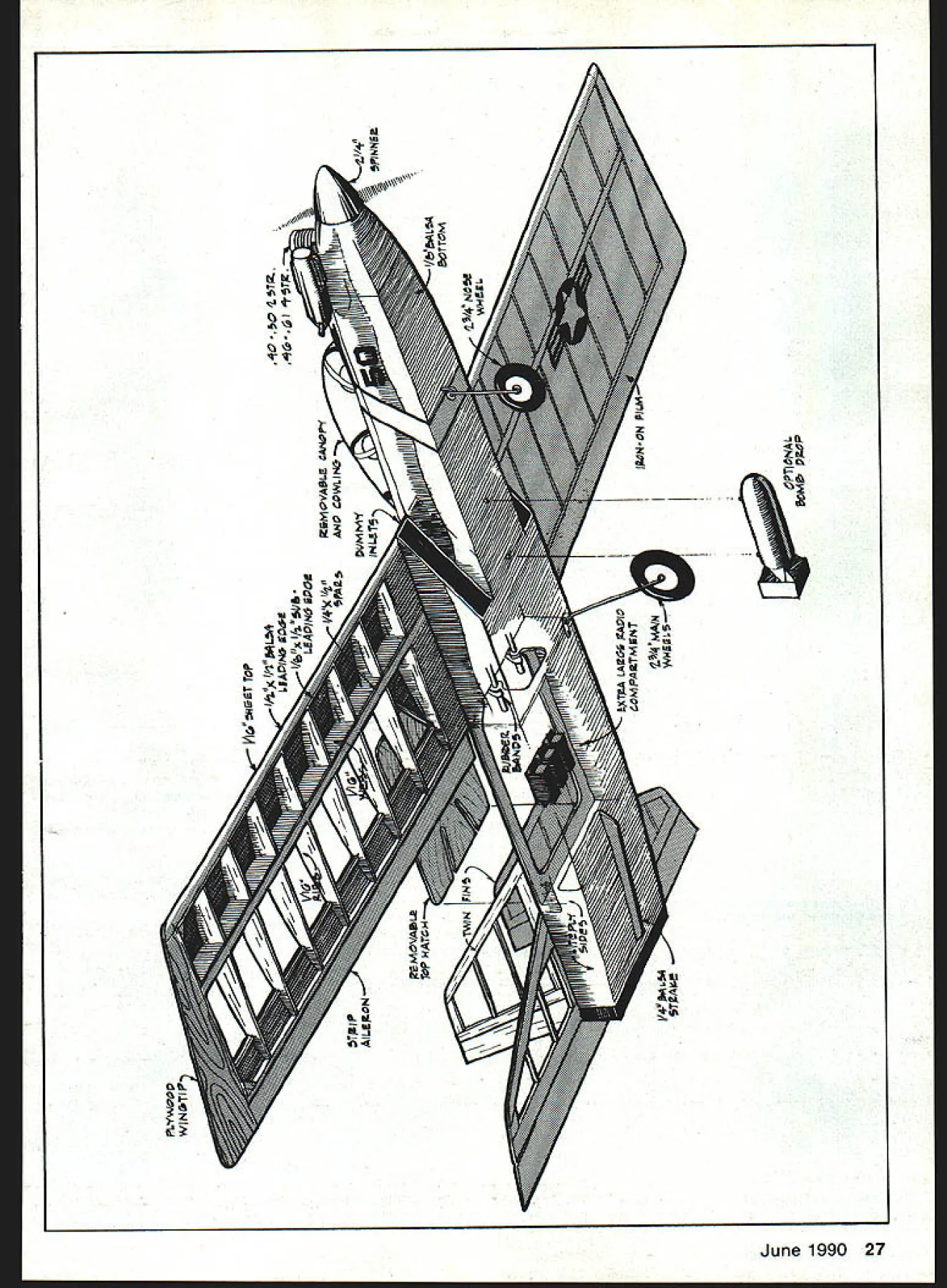
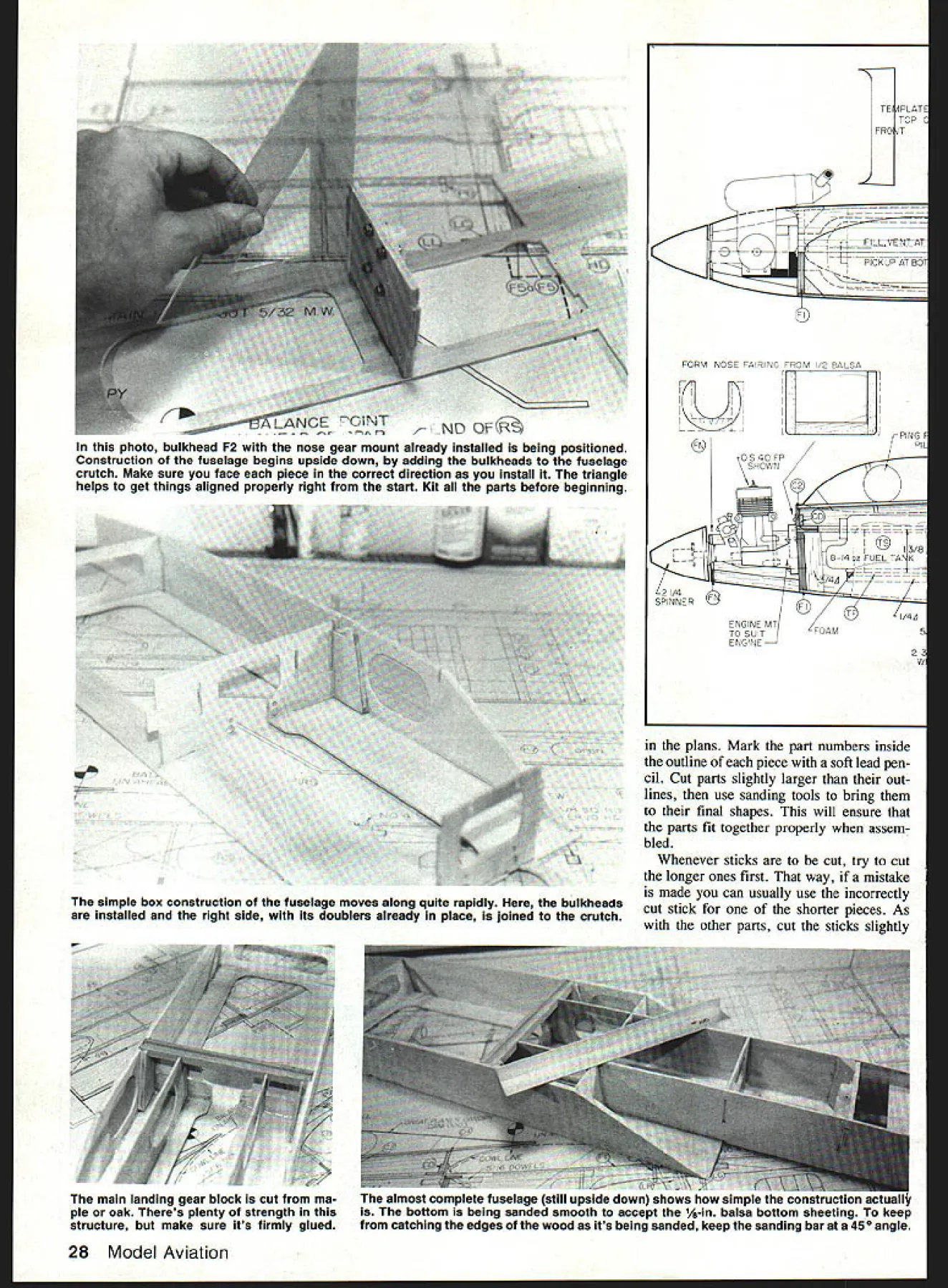
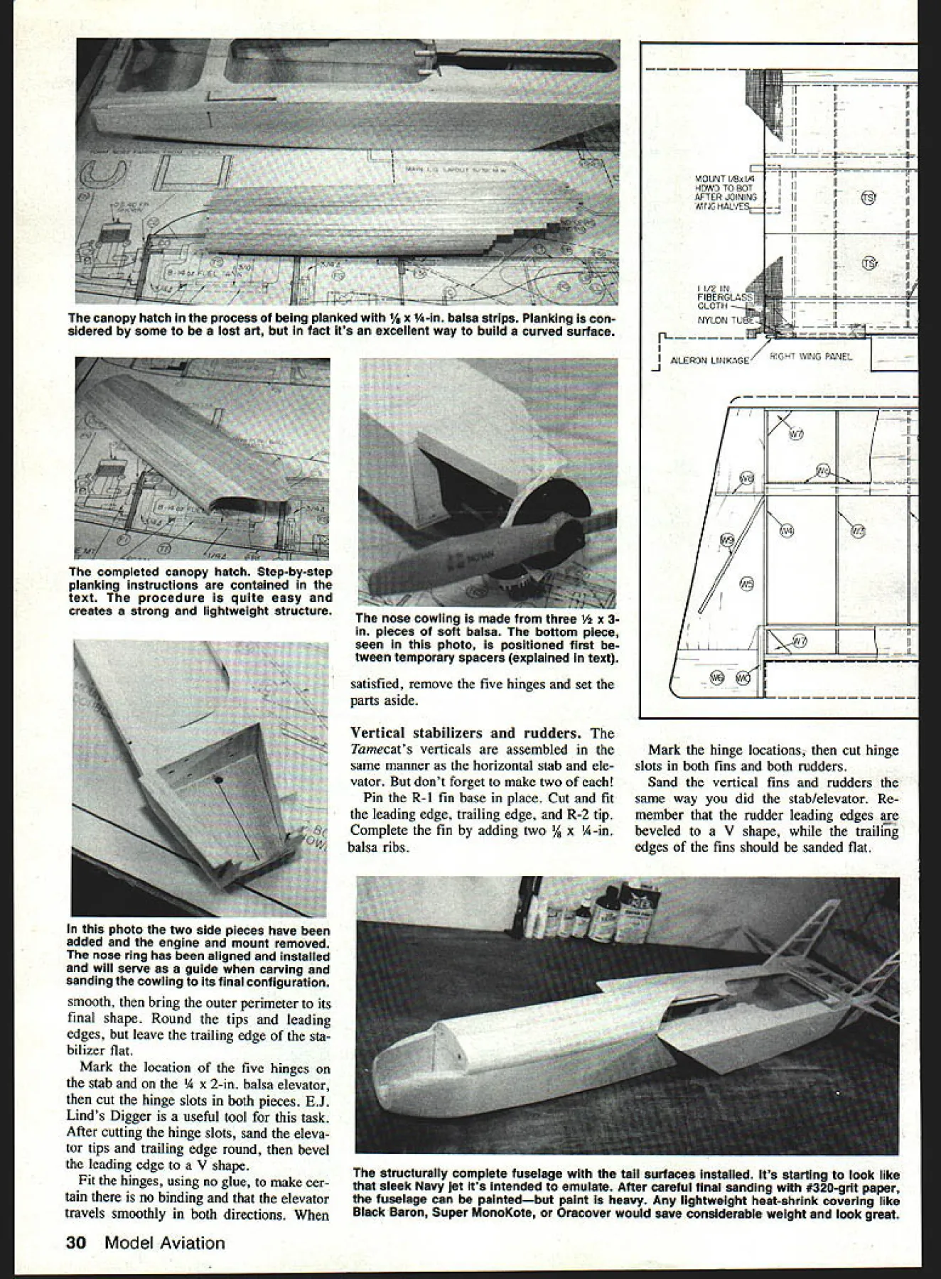
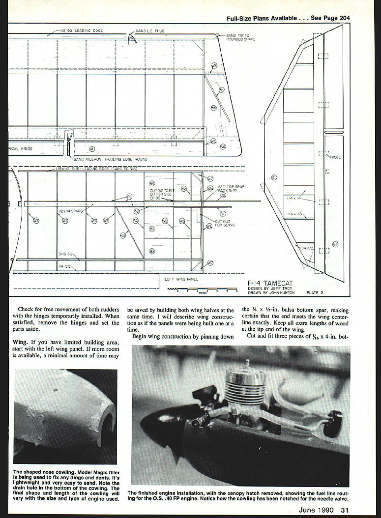
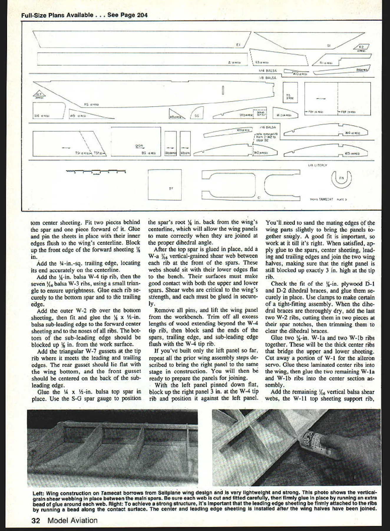

