
Trimming
July 2006 47
by Dean Pappas
Part 1 From the Ground Up
Is your trainer a well-behaved goldfish or a dangerous shark? It doesn’t take that much
effort to turn one into the other.
YOU LEARN a lot from watching what
happens at the flying field on a Sunday
afternoon and even more from the beginners.
You learn what the basic flying skills really
are and, most important, you see the
beginners struggling with their trainers’
shortcomings.
In all fairness, even the best of these
designs are often built (or assembled from
ARF kits) by inexperienced enthusiasts. It
would be almost impossible for it to be any
other way!
So much hard-earned experience goes into
building a well-behaved RC airplane, more
goes into installing the mechanical and
electronic systems, and even more goes into
adjusting or trimming for best flight
performance. The purpose of this “From the
Ground Up” installment is to make it easier to
gather that knowledge and experience.
When I refer to “best flight performance,”
I don’t mean making your trainer perform like
a P-51; I mean getting your model to perform
its intended “mission” as well as it was
designed to. For a trainer that mission is to be
well behaved, predictable, and have solid
control, especially during takeoff and landing.
The mission of sport and Scale airplanes is
similar to the following—with some
additions, depending on the type of model. It
would be good for a Scale airplane to be well
behaved while performing any maneuver that
is typical of the prototype. For the sport flier it
would be nice if the airplane’s predictable
behavior helped him or her “look good” while
enjoying the sport.
On the other hand, many airplanes have
what we often call a “personality.” That’s
code for “It ain’t quite right but I’ll live with
it.”
Sometimes experienced fliers do not even
realize they’re living with a model’s
undesirable quirks; either their skills are good
enough to cover for it or maybe they have
never had their hands on a dead-honest
airplane. It can be an eye-opening experience!
Students don’t have those skills yet, and they
have no basis for comparison at all; and that
can be a problem.
That, in a nutshell, is why we are here: to
learn that you don’t have to live with it. We
can make it better and your flying will benefit
at all skill levels, from beginner to highly
competent. Most important, as a student your
learning curve can be shortened if your
airplane is working with you rather than
against you.
A New Landscape
Today the availability of inexpensive
and ultrareliable radio-control units has
combined with the global economy to
provide a wide range of economically
viable prefabricated airframes. Those
would be the ARFs.
In many cases a flier can get into the
sport of RC flying and get reasonably
proficient before ever developing the
trimming skills that used to come,
incidentally, as part of the process of
learning things the old-fashioned way.
That’s progress, and there’s nothing
wrong with it! The untold secret is that
flying is more than just a hand-eye
coordination skill.
The best race-car drivers are the
ones who fully understand and can take
an active part in setting up their vehicles
for best performance. My goal is to give
relatively new fliers a leg up on the
aeromodeling version of that same
process.
Whether you build from kits, just
bought your first ARF, or have no
intention of gluing two balsa sticks
together, you can be a better pilot if you
understand how to best set up your
flying machine. MA
—Dean Pappas
The Kinds of Problems to Be Fixed: Your
Model’s “Personality Problems”: The list of
common trim problems is not that long. It
doesn’t have to be because any problem can
make flying your airplane difficult. Multiple
problems usually add up to more than the sum
of the individual parts. There is often more
than one cause for a particular problem, and
we must figure out where to attack.
1) Poor aileron control response
(especially at low airspeed) and directional
trim that changes at different airspeeds make
accurate flying difficult. These two problems
can make it unnecessarily hard to learn to
land.
It’s tough enough for a student to learn left
from right while on the landing approach, but
if the airplane tends to deviate to one side and
then the control you use for correction
becomes sluggish, you have the beginnings of
a panic situation. This is supposed to be fun,
and we just don’t need panic situations!
2) A tendency to veer off in one direction
(usually the left) when climbing or when full
power is applied adds an unnecessary
workload during takeoff. Combine this with
poor aileron control response, and you have
another potentially unsafe combination.
3) If your airplane drastically changes
pitch trim with changes in throttle and
airspeed (meaning it’s either climbing or
48 MODEL AVIATION
Forces, or torques, that contribute to pitch trim are in perfect balance anytime the model is
flying level, climbing at a constant rate, or gliding downward at a constant rate. Any
imbalance means the model is changing pitch angle. The engine downthrust, the lift of the
wing, the weight of the airplane, and the tail downforce all sit on the pitch see-saw.
Depending on the airfoil, the angle between the wing chord line and the horizontal stabilizer
chord line will be between zero and a few degrees, with the wing more positive, or nose-up,
than the tail. Often the designer will show a reference line, or datum, on plans. Many ARF
kits lack this nicety. The airflow, as it passes the wing, is affected by the action of lift so that
the flow rotates in the nose-up direction. This imparts an airspeed-dependent nose-down
reaction torque to the airframe.
diving without elevator input), it’s a problem
that can lead to a loss of airspeed and control
at the wrong time. This can combine with
both of the preceding to create even bigger
problems.
Depending on the airplane’s mission, we
often intentionally set it up to climb with full
throttle (but not too steeply), to maintain level
flight at cruise power (maybe a bit more than
half throttle), and to finally descend at a gentle
glide slope (with enough airspeed for good
control) at a fast idle.
4) This next problem is closely related to
the preceding problem. If the airplane does
not settle into a predictable glide slope when
the throttle is reduced, this can add to the
pilot’s workload during final approach and
landing. A proper glide has a predictable sink
rate that is just steep enough to maintain
adequate airspeed for good control, but it is
not so steep or so fast that it makes it hard to
get the airplane to settle to the ground in the
flare.
The flare is that last portion of the landing,
in which up-elevator is added to almost stop
the descent rate and bleed off the last bit of
excess airspeed. This makes the model touch
down in a three-point attitude if it is a taildragger
or with the main gear first and the
nose wheel an inch off the ground in the case
of a tricycle-geared model.
If the glide is too shallow, the airplane will
mush along with the nose up and with low
airspeed, leading to poor directional control
authority. This often leads to the problems in
item 1. You will often find experienced pilots
landing a particular airplane “hot,” or fast,
every time because the model has a
controllability problem at low speed.
The Pitch-Control Balancing Act:
Predictable control is a balancing act. There is
a balance of forces always at work to make
the airplane fly straight and level, to climb,
and to descend. When the forces are not
precisely in balance, the airplane will be
changing pitch—either nosing up into a climb
or dropping into a dive.
The dominant forces are aerodynamics,
gravity, and engine thrust. That’s not much of
a surprise, is it?
I don’t want to give a whole course on
aerodynamics here, so this explanation will
not be entirely rigorous, but I do want to give
you a feel for how these forces juggle so that
the kinds of adjustments we make later will
make sense.
For almost all “normal” airplanes the
horizontal tail holds the tail end of the airplane
down. The wing makes lift, and the act of
making lift creates a nose-down torque. This
is for two reasons, the first of which is that for
stable flight (again, for almost all normal
airplanes) the CG, or balance point, is in front
of the wing’s center of lift.
The second reason is that as the wing
bends the passing air downward, it can be said
to rotate the airflow; therefore, the air imparts
an opposite, nose-down rotation to the wing
The Short List
1) CG location or balance point
(fore and aft, from side to side).
2) Aileron differential.
3) Proper hinge gaps—especially
the ailerons and elevator.
4) Engine-thrust adjustment
(downthrust and right thrust).
5) Landing-gear location and
steering.
It doesn’t sound like much, but
assuming that your airplane is a
known good design this is pretty
much it.
Wing and horizontal tail incidence
angles can also cause problems if
they are wrong. However, for the
purposes of this article we will
assume that you have built the
airplane according to plan and the
flying-surface angles are correct.
We will also assume that the
vertical fin has been glued on
straight. Yes, if your problem-child
airplane looks like it was made in a
pretzel factory, we can help it
some—but not completely! MA
—Dean Pappas
Drawings and photos by the author except as noted
Pitch See-Saw
Incidence Angles and Downwash
July 2006 49
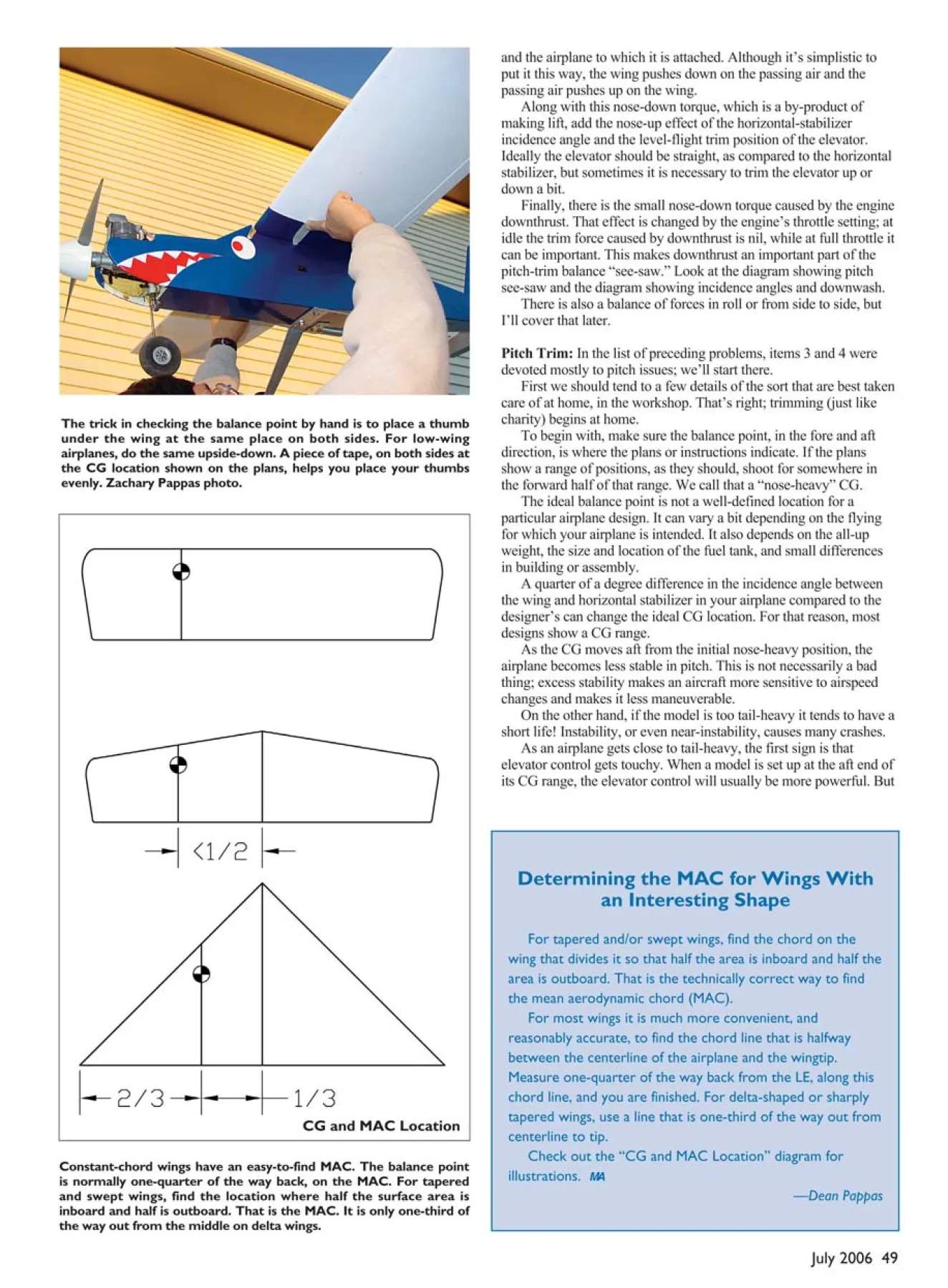
Constant-chord wings have an easy-to-find MAC. The balance point
is normally one-quarter of the way back, on the MAC. For tapered
and swept wings, find the location where half the surface area is
inboard and half is outboard. That is the MAC. It is only one-third of
the way out from the middle on delta wings.
The trick in checking the balance point by hand is to place a thumb
under the wing at the same place on both sides. For low-wing
airplanes, do the same upside-down. A piece of tape, on both sides at
the CG location shown on the plans, helps you place your thumbs
evenly. Zachary Pappas photo.
Determining the MAC for Wings With
an Interesting Shape
For tapered and/or swept wings, find the chord on the
wing that divides it so that half the area is inboard and half the
area is outboard. That is the technically correct way to find
the mean aerodynamic chord (MAC).
For most wings it is much more convenient, and
reasonably accurate, to find the chord line that is halfway
between the centerline of the airplane and the wingtip.
Measure one-quarter of the way back from the LE, along this
chord line, and you are finished. For delta-shaped or sharply
tapered wings, use a line that is one-third of the way out from
centerline to tip.
Check out the “CG and MAC Location” diagram for
illustrations. MA
—Dean Pappas
and the airplane to which it is attached. Although it’s simplistic to
put it this way, the wing pushes down on the passing air and the
passing air pushes up on the wing.
Along with this nose-down torque, which is a by-product of
making lift, add the nose-up effect of the horizontal-stabilizer
incidence angle and the level-flight trim position of the elevator.
Ideally the elevator should be straight, as compared to the horizontal
stabilizer, but sometimes it is necessary to trim the elevator up or
down a bit.
Finally, there is the small nose-down torque caused by the engine
downthrust. That effect is changed by the engine’s throttle setting; at
idle the trim force caused by downthrust is nil, while at full throttle it
can be important. This makes downthrust an important part of the
pitch-trim balance “see-saw.” Look at the diagram showing pitch
see-saw and the diagram showing incidence angles and downwash.
There is also a balance of forces in roll or from side to side, but
I’ll cover that later.
Pitch Trim: In the list of preceding problems, items 3 and 4 were
devoted mostly to pitch issues; we’ll start there.
First we should tend to a few details of the sort that are best taken
care of at home, in the workshop. That’s right; trimming (just like
charity) begins at home.
To begin with, make sure the balance point, in the fore and aft
direction, is where the plans or instructions indicate. If the plans
show a range of positions, as they should, shoot for somewhere in
the forward half of that range. We call that a “nose-heavy” CG.
The ideal balance point is not a well-defined location for a
particular airplane design. It can vary a bit depending on the flying
for which your airplane is intended. It also depends on the all-up
weight, the size and location of the fuel tank, and small differences
in building or assembly.
A quarter of a degree difference in the incidence angle between
the wing and horizontal stabilizer in your airplane compared to the
designer’s can change the ideal CG location. For that reason, most
designs show a CG range.
As the CG moves aft from the initial nose-heavy position, the
airplane becomes less stable in pitch. This is not necessarily a bad
thing; excess stability makes an aircraft more sensitive to airspeed
changes and makes it less maneuverable.
On the other hand, if the model is too tail-heavy it tends to have a
short life! Instability, or even near-instability, causes many crashes.
As an airplane gets close to tail-heavy, the first sign is that
elevator control gets touchy. When a model is set up at the aft end of
its CG range, the elevator control will usually be more powerful. But
CG and MAC Location
if it gets jumpy, or the airplane feels as
though the elevator trim is inconsistent, you
are flirting with tail-heaviness.
For more advanced sport airplanes with
semisymmetrical or symmetrical airfoils, an
important factor in where the CG belongs is
inverted flight. If it takes too much downelevator
to fly inverted, the model is likely
nose-heavy. If it takes no down-elevator, or
even climbs sometimes, it is definitely tailheavy.
A jumpy elevator is a sign of neardisastrous
tail-heaviness.
If your airplane always seems to run out
of elevator authority when it comes time to
flare for landing, it could be a sign of noseheaviness.
That is not the only reason for this
problem, but I’m mentioning it at this point
for completeness’ sake.
Checking the CG: To find the balance point,
you need to hang the airplane from
somewhere above its three-dimensional CG.
All that really means is that if your airplane
has a high or shoulder-mounted wing, you
can hold it up using one finger on each hand
under the wing. If you have a low-wing
airplane, you may find it easier to do this with
the model upside-down. A photo illustrates
this technique.
Make sure to place both fingers the same
distance back on each wing panel, and move
back and forth until the airplane hangs level.
A typical safe starting point for almost any
airplane is if the CG is placed at 25% of the
mean aerodynamic wing chord (MAC). The
farthest back the CG usually gets on a typical
trainer is 33%, or one-third, of the MAC.
Flying wing and tailless models typically
fly with the CG at 15%-20% of the MAC. On
a constant-chord wing, the 25% point is
exactly one-quarter of the way back from the
LE to the TE. Most trainers are designed with
constant-chord wings.
Once you have found the starting balance
point, move equipment if necessary to make
the airplane balance properly.
When the balance point is incorrect, the
first thing that typically gets moved is the
battery pack for the radio. Most often the
battery has to be moved forward under the
tank to move the balance forward. If that isn’t
enough, you may even consider using a
heavier, larger-capacity battery. After all,
nickel and cadmium are useful heavy metals,
and lead is just dead weight.
If you must add nose weight, place it as
far forward as practical so that less is
necessary. The weights that mount to the
crankshaft are not generally recommended.
If, on the other hand, your airplane is
nose-heavy to start with, it is slightly easier to
move the battery and receiver aft. The
receiver is relatively fragile in a crash and
expensive compared to the battery, so keep
the receiver behind the battery! If you must
add tail weight, place it as far aft as you can,
on the fuselage, because less will be
necessary.
One more thing: take a good look at your
airplane to make sure the wing and stabilizer
are mounted exactly as described on the
plans. You are looking for incorrect incidence
angles, which could force you to counteract
them with excessive amounts of elevator
deflection.
Oh yes, one more thing. Make sure the
elevator trim on the transmitter is centered
and the elevator control surface is straight.
That will require a control-linkage
adjustment. You don’t want to run out of
trim-lever movement because you didn’t set
the elevator straight to begin with. That goes
for all the other control surfaces too!
Going Flying: Most trainers are designed to
climb at full throttle and fly in level cruise at
a power setting just above half throttle
without having to change the elevator trim.
On takeoff your test pilot will take this into
account and wait until the airplane is throttled
back to cruise power before making any fine
elevator-trim adjustments for level flight.
Now, the importance of knowing that the
elevator was straight with the trim lever
centered will become apparent. As you first
put trim into the airplane, you already have
some idea of what you are dealing with. Does
it need up or down from the ideal, and
roughly how much?
That’s better than waiting until after
landing to look and see that all that furious
wiggling of the transmitter trim lever was just
to get things straight!
Pitch Flight Testing: Now that the airplane
is trimmed for level cruise, let’s do a couplefull. Without making elevator corrections, but
still keeping the wings level with minimal,
smooth aileron control inputs, watch the
climb that results.
Is the climb too shallow and fast? This
might be ideal for an advanced sport airplane,
but for a trainer you want a solid climb with
adequate airspeed.
Is the climb too steep? Watch to see if the
climb is so steep that the airspeed has
decayed.
Has aileron control become sloppy?
Is it difficult to promptly correct the
wind’s effects? If so, that is a sign that the
airspeed is too low because of the steepness of
the climb. In that case, you can do one of two
things: make the airplane less speed sensitive
by moving the CG aft and adding downelevator
trim or add more downthrust. If the
airplane climbs too shallow, you would do the
opposite.
How do you decide whether to change the
engine downthrust or the balance of
aerodynamic trim and balance point? Maybe
you should use a combination of the two. You
need more information, and to get it we use
the low-throttle glide test.
For the low-throttle test, set up a straight
and level pass, parallel to the runway and
roughly 100 feet up. Trim for cruise power
level flight and with your hand off the
elevator stick, quickly reduce the power to
maybe one or two “clicks” above a dead idle
just before the airplane passes you.
This is the throttle setting that most of us
use for the all-important final approach. Near
the threshold of the runway, the engine is
slowed to low idle.
Watch the glide slope that results, again
keeping the wings level but making no
elevator corrections. Does the model settle
into a nice glide angle or does it come down
like a space shuttle?
Maybe the glide slope is too shallow and
the airplane wallows along in a near stall; that
is, with the airspeed too low. In that case the
directional control will get sloppy too; the
ailerons may get sluggish or the airplane will
slowly drift off to one side even though it was
trimmed for straight and level flight.
Sometimes poor aileron control manifests
itself as what feels like a time lag between
when the aileron control is applied and when
the model actually starts to roll in the desired
direction. It will get better if you push the
nose down a tiny bit. That’s another hint that
the glide slope is too shallow.
Now that you’ve done both tests, it’s time
to assemble what you have observed and
make a change to the setup. If the model has
insufficient downthrust, the elevator would
have to be trimmed level or slightly down for
level flight compared to where it would be
with the correct downthrust. Alternatively, the
airplane would have to be nose-heavy. See the
pitch see-saw diagram.
If the airplane needs more downthrust, at
full power it will climb too steeply because
the nose-up engine thrust is great. It will also
glide too steeply when the nose-up engine
thrust is missing and the down-trim or noseheaviness
takes over.
It is also possible that the airplane climbs
too steeply under full power and glides okay
or a little steep if the model is nose-heavy.
That means it is overly stable in pitch and
responds to the added airspeed by trying to
climb too much.
How can you tell if this is the case? If the
elevator is trimmed up for level flight, even a
bit, this is a hint that the airplane is noseheavy
and the aerodynamic trim was
necessary to counteract it.
Which Pitch Adjustment to Make?
• If the climb or glide is too steep and the
elevator trim is up.
The trick in telling the difference between
nose-heaviness and insufficient downthrust in
a model that climbs too steeply under full
power is to look at the elevator trim. If the
airplane carries up-trim, move the CG back
approximately one-quarter inch, retrim for
cruise power level flight, and do the fullthrottle
climb and low-throttle glide tests
again.
If the elevator trim is still up compared to
the stabilizer, move the CG back another
quarter inch and retrim again until the elevator
trim is level or close. If the climb and glide
are acceptable, even though there is a bit of
elevator trim, it is okay to stop there. Even a
bit of down-trim is okay. After all, we are
interested in results.
If you have to move the CG back far
enough that down-elevator trim becomeslevel flight, you really should move the CG
forward the last step and start to add
downthrust.
• If the climb or glide is too steep and the
elevator trim is near neutral.
If the airplane had no noticeable up-trim to
begin with, add downthrust, retrim for cruise
power level flight, and do the climb and glide
tests again.
Of course it is possible that your model
needs both adjustments. Start by moving the
CG back to get rid of excess up-trim. If the
climb is still too steep, add downthrust.
• If things don’t behave.
If at any point in this process you move
the CG back and the model gets touchy in
pitch, you need to stop and check the CG
location. Your airplane is almost certainly
tail-heavy. Move the CG forward to the last
location where the elevator control felt
predictable.
It’s rare that an RC sport model or trainer
ever needs the CG to be placed more than
one-third of the way back on the MAC and,
as I mentioned earlier, a normal CG is closer
to one-quarter of the MAC. If you have
stumbled onto tail-heaviness using this
method, you need to put the CG back at a
position where the elevator control was
predictable.
If the airplane still needs a great deal of
elevator trim to fly level, you should look at
changing the wing incidence. If it needs a lot
of up-trim, shim the LE of the wing up on a
high-wing airplane. If the model needs a lot
of down-trim, shim the TE of the wing up.
When you change the wing incidence,
small steps such as 1/16 inch are best. If more
than one adjustment is necessary, so be it, but
drastic adjustments can have unpredictable
consequences.
Again, the goal is to get the model to trim
in cruise power level flight with the elevator
closely lined up with the stabilizer. Any
remaining problem with a steep climb and
glide is almost certainly because you need
more downthrust.
• If the climb or glide is too steep and the
elevator trim is down.
The likely cause for this is that the wing
and/or stabilizer incidences are wrong. The
wing and stabilizer incidence angles are
creating a strong nose-up tendency, which
gets even more powerful at high airspeed.
You either need negative (TE up)
incidence in the wing or positive (LE up)
incidence in the stabilizer. The wing is
usually easier to change. This is a sign of a
model that has excessive pitch stability and
excess horsepower.
Trainers are intentionally quite stable, but
such designs do not tolerate overpowering
well. In this case the cure is not to have less
power, but to put the airplane in “low gear”
with a propeller that limits the top airspeed.
A larger-diameter, low-pitch propeller or a
three-blade propeller with the same diameter
and lower pitch will help limit the excess
speed while harnessing the same horsepower.
This airspeed-limitation trick is typically
useful if the full-power climb is too steep.
Another way of reducing this problem is
to trail both ailerons up approximately 1/32
inch. I will not go into this at length right
now, but it will come up later in the section
about improving roll control on airplanes with
flat-bottom airfoils.
The Opposite Situation:
• If the climb or glide is too shallow and the
elevator trim is down—even a bit.
If the model climbs well, or even a bit
shallow, at full throttle and then glides nicely
or a bit shallow, you want the airplane to
change trim with airspeed more than it
already does.
Look at the elevator trim to tell whether or
not you should reduce the downthrust or push
the CG forward. If the elevator is trimmed
down, move the CG forward, retrim for cruise
power level flight, and redo the full-throttle
and low-throttle tests. Continue making
adjustments until the elevator trim is level, or
at least close to level with the stabilizer.
You may start by moving the CG forward
to get rid of the down-elevator trim, and then
reduce the downthrust once the elevator trim
in cruise power level flight is zeroed out.
• If the climb or glide is too shallow and the
elevator trim is level, or even a bit up.
If the elevator was not trimmed down, the
CG position is not the issue. Reduce the
downthrust.
That about covers basic pitch trim. Next
month I will share a method of checking
downthrust that is more appropriate for highperformance
sport models and airplanes that
are intended to be flown fast rather than slow,
such as trainers. Then we will test for and
adjust right thrust.
Until then, remember that your equipment
should be set up to work with you—not
against you! MA
Dean Pappas
[email protected]

Edition: Model Aviation - 2006/07
Page Numbers: 47,48,49,50,51,52

Edition: Model Aviation - 2006/07
Page Numbers: 47,48,49,50,51,52
Trimming
July 2006 47
by Dean Pappas
Part 1 From the Ground Up
Is your trainer a well-behaved goldfish or a dangerous shark? It doesn’t take that much
effort to turn one into the other.
YOU LEARN a lot from watching what
happens at the flying field on a Sunday
afternoon and even more from the beginners.
You learn what the basic flying skills really
are and, most important, you see the
beginners struggling with their trainers’
shortcomings.
In all fairness, even the best of these
designs are often built (or assembled from
ARF kits) by inexperienced enthusiasts. It
would be almost impossible for it to be any
other way!
So much hard-earned experience goes into
building a well-behaved RC airplane, more
goes into installing the mechanical and
electronic systems, and even more goes into
adjusting or trimming for best flight
performance. The purpose of this “From the
Ground Up” installment is to make it easier to
gather that knowledge and experience.
When I refer to “best flight performance,”
I don’t mean making your trainer perform like
a P-51; I mean getting your model to perform
its intended “mission” as well as it was
designed to. For a trainer that mission is to be
well behaved, predictable, and have solid
control, especially during takeoff and landing.
The mission of sport and Scale airplanes is
similar to the following—with some
additions, depending on the type of model. It
would be good for a Scale airplane to be well
behaved while performing any maneuver that
is typical of the prototype. For the sport flier it
would be nice if the airplane’s predictable
behavior helped him or her “look good” while
enjoying the sport.
On the other hand, many airplanes have
what we often call a “personality.” That’s
code for “It ain’t quite right but I’ll live with
it.”
Sometimes experienced fliers do not even
realize they’re living with a model’s
undesirable quirks; either their skills are good
enough to cover for it or maybe they have
never had their hands on a dead-honest
airplane. It can be an eye-opening experience!
Students don’t have those skills yet, and they
have no basis for comparison at all; and that
can be a problem.
That, in a nutshell, is why we are here: to
learn that you don’t have to live with it. We
can make it better and your flying will benefit
at all skill levels, from beginner to highly
competent. Most important, as a student your
learning curve can be shortened if your
airplane is working with you rather than
against you.
A New Landscape
Today the availability of inexpensive
and ultrareliable radio-control units has
combined with the global economy to
provide a wide range of economically
viable prefabricated airframes. Those
would be the ARFs.
In many cases a flier can get into the
sport of RC flying and get reasonably
proficient before ever developing the
trimming skills that used to come,
incidentally, as part of the process of
learning things the old-fashioned way.
That’s progress, and there’s nothing
wrong with it! The untold secret is that
flying is more than just a hand-eye
coordination skill.
The best race-car drivers are the
ones who fully understand and can take
an active part in setting up their vehicles
for best performance. My goal is to give
relatively new fliers a leg up on the
aeromodeling version of that same
process.
Whether you build from kits, just
bought your first ARF, or have no
intention of gluing two balsa sticks
together, you can be a better pilot if you
understand how to best set up your
flying machine. MA
—Dean Pappas
The Kinds of Problems to Be Fixed: Your
Model’s “Personality Problems”: The list of
common trim problems is not that long. It
doesn’t have to be because any problem can
make flying your airplane difficult. Multiple
problems usually add up to more than the sum
of the individual parts. There is often more
than one cause for a particular problem, and
we must figure out where to attack.
1) Poor aileron control response
(especially at low airspeed) and directional
trim that changes at different airspeeds make
accurate flying difficult. These two problems
can make it unnecessarily hard to learn to
land.
It’s tough enough for a student to learn left
from right while on the landing approach, but
if the airplane tends to deviate to one side and
then the control you use for correction
becomes sluggish, you have the beginnings of
a panic situation. This is supposed to be fun,
and we just don’t need panic situations!
2) A tendency to veer off in one direction
(usually the left) when climbing or when full
power is applied adds an unnecessary
workload during takeoff. Combine this with
poor aileron control response, and you have
another potentially unsafe combination.
3) If your airplane drastically changes
pitch trim with changes in throttle and
airspeed (meaning it’s either climbing or
48 MODEL AVIATION
Forces, or torques, that contribute to pitch trim are in perfect balance anytime the model is
flying level, climbing at a constant rate, or gliding downward at a constant rate. Any
imbalance means the model is changing pitch angle. The engine downthrust, the lift of the
wing, the weight of the airplane, and the tail downforce all sit on the pitch see-saw.
Depending on the airfoil, the angle between the wing chord line and the horizontal stabilizer
chord line will be between zero and a few degrees, with the wing more positive, or nose-up,
than the tail. Often the designer will show a reference line, or datum, on plans. Many ARF
kits lack this nicety. The airflow, as it passes the wing, is affected by the action of lift so that
the flow rotates in the nose-up direction. This imparts an airspeed-dependent nose-down
reaction torque to the airframe.
diving without elevator input), it’s a problem
that can lead to a loss of airspeed and control
at the wrong time. This can combine with
both of the preceding to create even bigger
problems.
Depending on the airplane’s mission, we
often intentionally set it up to climb with full
throttle (but not too steeply), to maintain level
flight at cruise power (maybe a bit more than
half throttle), and to finally descend at a gentle
glide slope (with enough airspeed for good
control) at a fast idle.
4) This next problem is closely related to
the preceding problem. If the airplane does
not settle into a predictable glide slope when
the throttle is reduced, this can add to the
pilot’s workload during final approach and
landing. A proper glide has a predictable sink
rate that is just steep enough to maintain
adequate airspeed for good control, but it is
not so steep or so fast that it makes it hard to
get the airplane to settle to the ground in the
flare.
The flare is that last portion of the landing,
in which up-elevator is added to almost stop
the descent rate and bleed off the last bit of
excess airspeed. This makes the model touch
down in a three-point attitude if it is a taildragger
or with the main gear first and the
nose wheel an inch off the ground in the case
of a tricycle-geared model.
If the glide is too shallow, the airplane will
mush along with the nose up and with low
airspeed, leading to poor directional control
authority. This often leads to the problems in
item 1. You will often find experienced pilots
landing a particular airplane “hot,” or fast,
every time because the model has a
controllability problem at low speed.
The Pitch-Control Balancing Act:
Predictable control is a balancing act. There is
a balance of forces always at work to make
the airplane fly straight and level, to climb,
and to descend. When the forces are not
precisely in balance, the airplane will be
changing pitch—either nosing up into a climb
or dropping into a dive.
The dominant forces are aerodynamics,
gravity, and engine thrust. That’s not much of
a surprise, is it?
I don’t want to give a whole course on
aerodynamics here, so this explanation will
not be entirely rigorous, but I do want to give
you a feel for how these forces juggle so that
the kinds of adjustments we make later will
make sense.
For almost all “normal” airplanes the
horizontal tail holds the tail end of the airplane
down. The wing makes lift, and the act of
making lift creates a nose-down torque. This
is for two reasons, the first of which is that for
stable flight (again, for almost all normal
airplanes) the CG, or balance point, is in front
of the wing’s center of lift.
The second reason is that as the wing
bends the passing air downward, it can be said
to rotate the airflow; therefore, the air imparts
an opposite, nose-down rotation to the wing
The Short List
1) CG location or balance point
(fore and aft, from side to side).
2) Aileron differential.
3) Proper hinge gaps—especially
the ailerons and elevator.
4) Engine-thrust adjustment
(downthrust and right thrust).
5) Landing-gear location and
steering.
It doesn’t sound like much, but
assuming that your airplane is a
known good design this is pretty
much it.
Wing and horizontal tail incidence
angles can also cause problems if
they are wrong. However, for the
purposes of this article we will
assume that you have built the
airplane according to plan and the
flying-surface angles are correct.
We will also assume that the
vertical fin has been glued on
straight. Yes, if your problem-child
airplane looks like it was made in a
pretzel factory, we can help it
some—but not completely! MA
—Dean Pappas
Drawings and photos by the author except as noted
Pitch See-Saw
Incidence Angles and Downwash
July 2006 49
Constant-chord wings have an easy-to-find MAC. The balance point
is normally one-quarter of the way back, on the MAC. For tapered
and swept wings, find the location where half the surface area is
inboard and half is outboard. That is the MAC. It is only one-third of
the way out from the middle on delta wings.
The trick in checking the balance point by hand is to place a thumb
under the wing at the same place on both sides. For low-wing
airplanes, do the same upside-down. A piece of tape, on both sides at
the CG location shown on the plans, helps you place your thumbs
evenly. Zachary Pappas photo.
Determining the MAC for Wings With
an Interesting Shape
For tapered and/or swept wings, find the chord on the
wing that divides it so that half the area is inboard and half the
area is outboard. That is the technically correct way to find
the mean aerodynamic chord (MAC).
For most wings it is much more convenient, and
reasonably accurate, to find the chord line that is halfway
between the centerline of the airplane and the wingtip.
Measure one-quarter of the way back from the LE, along this
chord line, and you are finished. For delta-shaped or sharply
tapered wings, use a line that is one-third of the way out from
centerline to tip.
Check out the “CG and MAC Location” diagram for
illustrations. MA
—Dean Pappas
and the airplane to which it is attached. Although it’s simplistic to
put it this way, the wing pushes down on the passing air and the
passing air pushes up on the wing.
Along with this nose-down torque, which is a by-product of
making lift, add the nose-up effect of the horizontal-stabilizer
incidence angle and the level-flight trim position of the elevator.
Ideally the elevator should be straight, as compared to the horizontal
stabilizer, but sometimes it is necessary to trim the elevator up or
down a bit.
Finally, there is the small nose-down torque caused by the engine
downthrust. That effect is changed by the engine’s throttle setting; at
idle the trim force caused by downthrust is nil, while at full throttle it
can be important. This makes downthrust an important part of the
pitch-trim balance “see-saw.” Look at the diagram showing pitch
see-saw and the diagram showing incidence angles and downwash.
There is also a balance of forces in roll or from side to side, but
I’ll cover that later.
Pitch Trim: In the list of preceding problems, items 3 and 4 were
devoted mostly to pitch issues; we’ll start there.
First we should tend to a few details of the sort that are best taken
care of at home, in the workshop. That’s right; trimming (just like
charity) begins at home.
To begin with, make sure the balance point, in the fore and aft
direction, is where the plans or instructions indicate. If the plans
show a range of positions, as they should, shoot for somewhere in
the forward half of that range. We call that a “nose-heavy” CG.
The ideal balance point is not a well-defined location for a
particular airplane design. It can vary a bit depending on the flying
for which your airplane is intended. It also depends on the all-up
weight, the size and location of the fuel tank, and small differences
in building or assembly.
A quarter of a degree difference in the incidence angle between
the wing and horizontal stabilizer in your airplane compared to the
designer’s can change the ideal CG location. For that reason, most
designs show a CG range.
As the CG moves aft from the initial nose-heavy position, the
airplane becomes less stable in pitch. This is not necessarily a bad
thing; excess stability makes an aircraft more sensitive to airspeed
changes and makes it less maneuverable.
On the other hand, if the model is too tail-heavy it tends to have a
short life! Instability, or even near-instability, causes many crashes.
As an airplane gets close to tail-heavy, the first sign is that
elevator control gets touchy. When a model is set up at the aft end of
its CG range, the elevator control will usually be more powerful. But
CG and MAC Location
if it gets jumpy, or the airplane feels as
though the elevator trim is inconsistent, you
are flirting with tail-heaviness.
For more advanced sport airplanes with
semisymmetrical or symmetrical airfoils, an
important factor in where the CG belongs is
inverted flight. If it takes too much downelevator
to fly inverted, the model is likely
nose-heavy. If it takes no down-elevator, or
even climbs sometimes, it is definitely tailheavy.
A jumpy elevator is a sign of neardisastrous
tail-heaviness.
If your airplane always seems to run out
of elevator authority when it comes time to
flare for landing, it could be a sign of noseheaviness.
That is not the only reason for this
problem, but I’m mentioning it at this point
for completeness’ sake.
Checking the CG: To find the balance point,
you need to hang the airplane from
somewhere above its three-dimensional CG.
All that really means is that if your airplane
has a high or shoulder-mounted wing, you
can hold it up using one finger on each hand
under the wing. If you have a low-wing
airplane, you may find it easier to do this with
the model upside-down. A photo illustrates
this technique.
Make sure to place both fingers the same
distance back on each wing panel, and move
back and forth until the airplane hangs level.
A typical safe starting point for almost any
airplane is if the CG is placed at 25% of the
mean aerodynamic wing chord (MAC). The
farthest back the CG usually gets on a typical
trainer is 33%, or one-third, of the MAC.
Flying wing and tailless models typically
fly with the CG at 15%-20% of the MAC. On
a constant-chord wing, the 25% point is
exactly one-quarter of the way back from the
LE to the TE. Most trainers are designed with
constant-chord wings.
Once you have found the starting balance
point, move equipment if necessary to make
the airplane balance properly.
When the balance point is incorrect, the
first thing that typically gets moved is the
battery pack for the radio. Most often the
battery has to be moved forward under the
tank to move the balance forward. If that isn’t
enough, you may even consider using a
heavier, larger-capacity battery. After all,
nickel and cadmium are useful heavy metals,
and lead is just dead weight.
If you must add nose weight, place it as
far forward as practical so that less is
necessary. The weights that mount to the
crankshaft are not generally recommended.
If, on the other hand, your airplane is
nose-heavy to start with, it is slightly easier to
move the battery and receiver aft. The
receiver is relatively fragile in a crash and
expensive compared to the battery, so keep
the receiver behind the battery! If you must
add tail weight, place it as far aft as you can,
on the fuselage, because less will be
necessary.
One more thing: take a good look at your
airplane to make sure the wing and stabilizer
are mounted exactly as described on the
plans. You are looking for incorrect incidence
angles, which could force you to counteract
them with excessive amounts of elevator
deflection.
Oh yes, one more thing. Make sure the
elevator trim on the transmitter is centered
and the elevator control surface is straight.
That will require a control-linkage
adjustment. You don’t want to run out of
trim-lever movement because you didn’t set
the elevator straight to begin with. That goes
for all the other control surfaces too!
Going Flying: Most trainers are designed to
climb at full throttle and fly in level cruise at
a power setting just above half throttle
without having to change the elevator trim.
On takeoff your test pilot will take this into
account and wait until the airplane is throttled
back to cruise power before making any fine
elevator-trim adjustments for level flight.
Now, the importance of knowing that the
elevator was straight with the trim lever
centered will become apparent. As you first
put trim into the airplane, you already have
some idea of what you are dealing with. Does
it need up or down from the ideal, and
roughly how much?
That’s better than waiting until after
landing to look and see that all that furious
wiggling of the transmitter trim lever was just
to get things straight!
Pitch Flight Testing: Now that the airplane
is trimmed for level cruise, let’s do a couplefull. Without making elevator corrections, but
still keeping the wings level with minimal,
smooth aileron control inputs, watch the
climb that results.
Is the climb too shallow and fast? This
might be ideal for an advanced sport airplane,
but for a trainer you want a solid climb with
adequate airspeed.
Is the climb too steep? Watch to see if the
climb is so steep that the airspeed has
decayed.
Has aileron control become sloppy?
Is it difficult to promptly correct the
wind’s effects? If so, that is a sign that the
airspeed is too low because of the steepness of
the climb. In that case, you can do one of two
things: make the airplane less speed sensitive
by moving the CG aft and adding downelevator
trim or add more downthrust. If the
airplane climbs too shallow, you would do the
opposite.
How do you decide whether to change the
engine downthrust or the balance of
aerodynamic trim and balance point? Maybe
you should use a combination of the two. You
need more information, and to get it we use
the low-throttle glide test.
For the low-throttle test, set up a straight
and level pass, parallel to the runway and
roughly 100 feet up. Trim for cruise power
level flight and with your hand off the
elevator stick, quickly reduce the power to
maybe one or two “clicks” above a dead idle
just before the airplane passes you.
This is the throttle setting that most of us
use for the all-important final approach. Near
the threshold of the runway, the engine is
slowed to low idle.
Watch the glide slope that results, again
keeping the wings level but making no
elevator corrections. Does the model settle
into a nice glide angle or does it come down
like a space shuttle?
Maybe the glide slope is too shallow and
the airplane wallows along in a near stall; that
is, with the airspeed too low. In that case the
directional control will get sloppy too; the
ailerons may get sluggish or the airplane will
slowly drift off to one side even though it was
trimmed for straight and level flight.
Sometimes poor aileron control manifests
itself as what feels like a time lag between
when the aileron control is applied and when
the model actually starts to roll in the desired
direction. It will get better if you push the
nose down a tiny bit. That’s another hint that
the glide slope is too shallow.
Now that you’ve done both tests, it’s time
to assemble what you have observed and
make a change to the setup. If the model has
insufficient downthrust, the elevator would
have to be trimmed level or slightly down for
level flight compared to where it would be
with the correct downthrust. Alternatively, the
airplane would have to be nose-heavy. See the
pitch see-saw diagram.
If the airplane needs more downthrust, at
full power it will climb too steeply because
the nose-up engine thrust is great. It will also
glide too steeply when the nose-up engine
thrust is missing and the down-trim or noseheaviness
takes over.
It is also possible that the airplane climbs
too steeply under full power and glides okay
or a little steep if the model is nose-heavy.
That means it is overly stable in pitch and
responds to the added airspeed by trying to
climb too much.
How can you tell if this is the case? If the
elevator is trimmed up for level flight, even a
bit, this is a hint that the airplane is noseheavy
and the aerodynamic trim was
necessary to counteract it.
Which Pitch Adjustment to Make?
• If the climb or glide is too steep and the
elevator trim is up.
The trick in telling the difference between
nose-heaviness and insufficient downthrust in
a model that climbs too steeply under full
power is to look at the elevator trim. If the
airplane carries up-trim, move the CG back
approximately one-quarter inch, retrim for
cruise power level flight, and do the fullthrottle
climb and low-throttle glide tests
again.
If the elevator trim is still up compared to
the stabilizer, move the CG back another
quarter inch and retrim again until the elevator
trim is level or close. If the climb and glide
are acceptable, even though there is a bit of
elevator trim, it is okay to stop there. Even a
bit of down-trim is okay. After all, we are
interested in results.
If you have to move the CG back far
enough that down-elevator trim becomeslevel flight, you really should move the CG
forward the last step and start to add
downthrust.
• If the climb or glide is too steep and the
elevator trim is near neutral.
If the airplane had no noticeable up-trim to
begin with, add downthrust, retrim for cruise
power level flight, and do the climb and glide
tests again.
Of course it is possible that your model
needs both adjustments. Start by moving the
CG back to get rid of excess up-trim. If the
climb is still too steep, add downthrust.
• If things don’t behave.
If at any point in this process you move
the CG back and the model gets touchy in
pitch, you need to stop and check the CG
location. Your airplane is almost certainly
tail-heavy. Move the CG forward to the last
location where the elevator control felt
predictable.
It’s rare that an RC sport model or trainer
ever needs the CG to be placed more than
one-third of the way back on the MAC and,
as I mentioned earlier, a normal CG is closer
to one-quarter of the MAC. If you have
stumbled onto tail-heaviness using this
method, you need to put the CG back at a
position where the elevator control was
predictable.
If the airplane still needs a great deal of
elevator trim to fly level, you should look at
changing the wing incidence. If it needs a lot
of up-trim, shim the LE of the wing up on a
high-wing airplane. If the model needs a lot
of down-trim, shim the TE of the wing up.
When you change the wing incidence,
small steps such as 1/16 inch are best. If more
than one adjustment is necessary, so be it, but
drastic adjustments can have unpredictable
consequences.
Again, the goal is to get the model to trim
in cruise power level flight with the elevator
closely lined up with the stabilizer. Any
remaining problem with a steep climb and
glide is almost certainly because you need
more downthrust.
• If the climb or glide is too steep and the
elevator trim is down.
The likely cause for this is that the wing
and/or stabilizer incidences are wrong. The
wing and stabilizer incidence angles are
creating a strong nose-up tendency, which
gets even more powerful at high airspeed.
You either need negative (TE up)
incidence in the wing or positive (LE up)
incidence in the stabilizer. The wing is
usually easier to change. This is a sign of a
model that has excessive pitch stability and
excess horsepower.
Trainers are intentionally quite stable, but
such designs do not tolerate overpowering
well. In this case the cure is not to have less
power, but to put the airplane in “low gear”
with a propeller that limits the top airspeed.
A larger-diameter, low-pitch propeller or a
three-blade propeller with the same diameter
and lower pitch will help limit the excess
speed while harnessing the same horsepower.
This airspeed-limitation trick is typically
useful if the full-power climb is too steep.
Another way of reducing this problem is
to trail both ailerons up approximately 1/32
inch. I will not go into this at length right
now, but it will come up later in the section
about improving roll control on airplanes with
flat-bottom airfoils.
The Opposite Situation:
• If the climb or glide is too shallow and the
elevator trim is down—even a bit.
If the model climbs well, or even a bit
shallow, at full throttle and then glides nicely
or a bit shallow, you want the airplane to
change trim with airspeed more than it
already does.
Look at the elevator trim to tell whether or
not you should reduce the downthrust or push
the CG forward. If the elevator is trimmed
down, move the CG forward, retrim for cruise
power level flight, and redo the full-throttle
and low-throttle tests. Continue making
adjustments until the elevator trim is level, or
at least close to level with the stabilizer.
You may start by moving the CG forward
to get rid of the down-elevator trim, and then
reduce the downthrust once the elevator trim
in cruise power level flight is zeroed out.
• If the climb or glide is too shallow and the
elevator trim is level, or even a bit up.
If the elevator was not trimmed down, the
CG position is not the issue. Reduce the
downthrust.
That about covers basic pitch trim. Next
month I will share a method of checking
downthrust that is more appropriate for highperformance
sport models and airplanes that
are intended to be flown fast rather than slow,
such as trainers. Then we will test for and
adjust right thrust.
Until then, remember that your equipment
should be set up to work with you—not
against you! MA
Dean Pappas
[email protected]

