
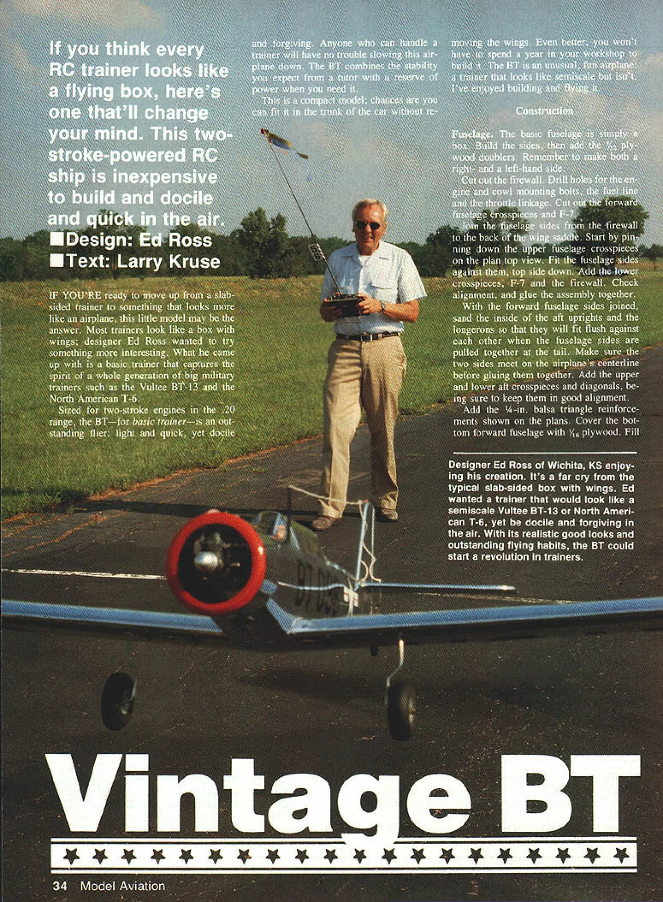
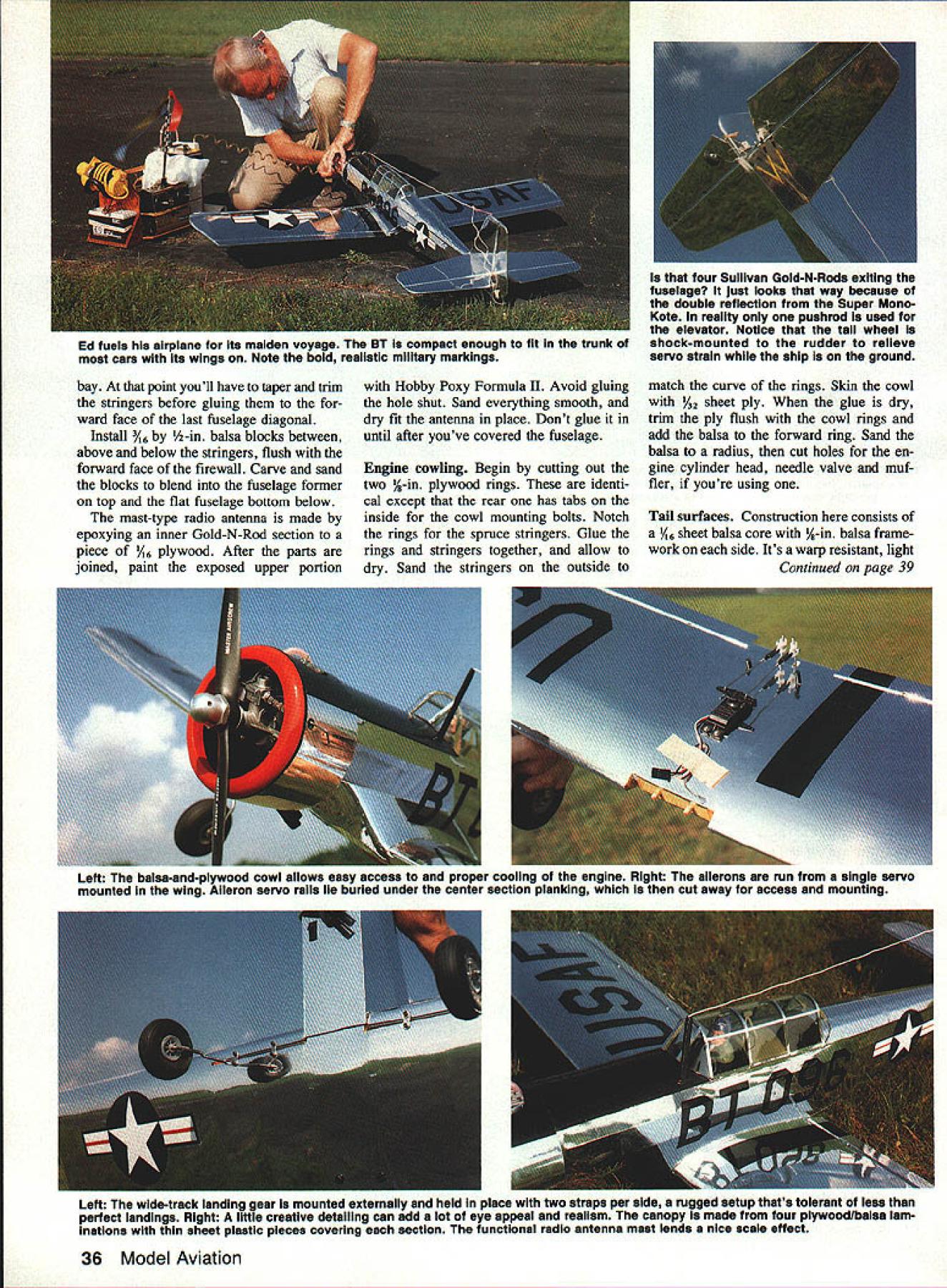
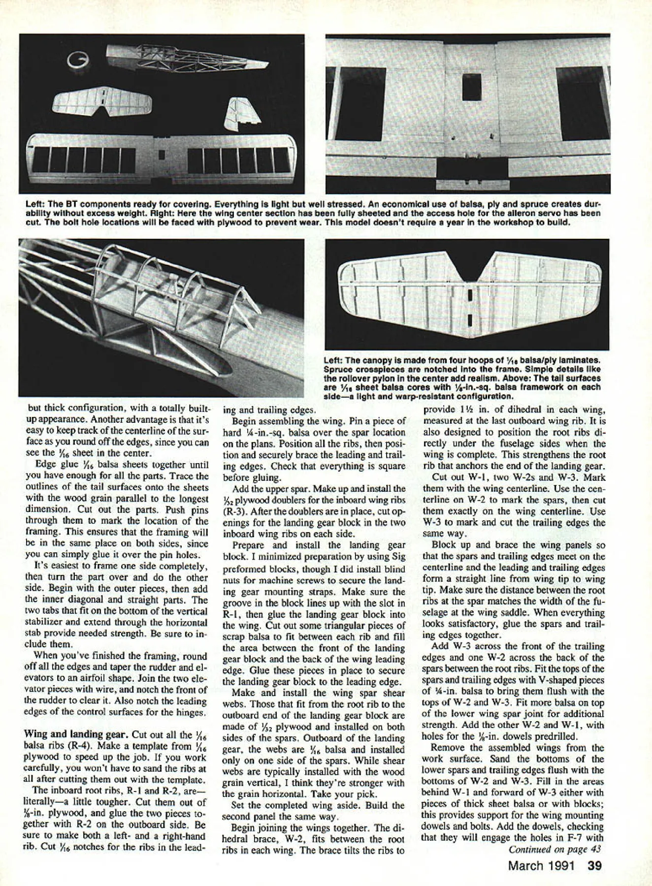
NO OCR TEXT BT three-quarter view sleek attractive lines evoke whole generation vintage military trainers duplicating partic ular airplane models wide landing gear stance gives exceptional ground-handling characteristics especially tail-dragger Rocksteady yet light nimble ship pleasure fly new filer gains confidence can add power really make move upper aft portion last upper crosspiece rear %-in sheet balsa Add servo rails wing mount ing bolt blocks inside fuselage Cut out lower aft portion both lower fuselage longerons install piece /16 ply tail wheel mount good time choose control linkage used Sullivan Gold-N-Rods rudder elevator prototype stall outer portions Gold-N-Rods Secure firmly exit fuse lage rear add cross support middle fuse Leave front ends loose time being throttle used cable inside inner portion GoldN-Rod Secure throttle passes through firewall leaving aft portion free now Fill cockpit floor A-in sheet balsa Cut out formers Install F-i through F-4 F-8 through F-li mak ing sure vertical properly aligned upper crosspieces Add A-in-sq balsa stringers Cover top ward fuselage /16 sheet balsa Install two pieces A-in-sq balsa along sides cockpit insert F-5 F-6 between Add -in balsa stringers cover /16 balsa sheet Make install rollover bar Make canopy frame four canopy hoops C-i through C-4 lamination /16 plywood /16 balsa Cut out ply wood parts first glue /16 sheet balsa ply trim balsa match its shape Cut file notches hoops spruce frame members run fore aft Install hoops checking theyre vertical square notch install straight A-in-sq spruce frame mem bers Add short A-in-sq spruce sticks form edges windshield rear panel canopy will have removed cover fuselage its easier locate properly before covering place two stringers side fuselage installed next resemble formers First glue two pieces / x /2-in sheet balsa fuselage sides flush forward edge firewall glue x nger supports latter should about 1 longjust distance tween /l6 x A-in balsa stringers Glue stringers positioning wide side horizontally maximum width Begin front glue over stringer supports until reach trailing edge wing Aft trailing edge glue stringers fuselage uprights diago nals until reach front last open March 1991 35 Ed Ross poses BT Chrome Super MonoKote stick-on insignia Major Decals give little 20-powered ship military realism belles Its trainer heritage Ed fuels airplane Its maiden voyage BT compact enough fit trunk moat cars its wings Note bold realistic military markings four Sullivan Gold-N-Rods exiting fuselage just looks way because double reflection Super Mono Kote reality pushrod used elevator Notice tall wheel shock-mounted rudder relieve servo strain whlie ship ground bay point youll have taper trim stringers before gluing ward face last fuselage diagonal Install /6 A-in balsa blocks between above below stringers flush forward face firewall Carve sand blocks blend fuselage former top flat fuselage bottom below mast-type radio antenna made epoxying inner Gold-N-Rod section piece /l6 plywood After parts joined paint exposed upper portion Hobby Poxy Formula II Avoid gluing hole shut Sand everything smooth dry fit antenna place Dont glue until after youve covered fuselage Engine cowling Begin cutting out two %-in plywood rings identi cal except rear has tabs inside cowl mounting bolts Notch rings spruce stringers Glue rings stringers together allow dry Sand stringers outside match curve rings Skin cowl /32 sheet ply glue dry trim ply flush cowl rings add balsa forward ring Sand balsa radius cut holes en gine cylinder head needle valve muf fler youre using Tail surfaces Construction consists V16 sheet balsa core A-in balsa frame work side Its warp resistant light Continued page 39 Left The balsa-and-plywood cowl allows easy access ana proper cooing ot inc engine HIgni ne ailerons run single servo mounted wing Aileron servo rails lie buried under center section plankIng cut away access mounting Left The wIde-track landing gear mounted externally held place two straps per aide rugged setup thats tolerant less perfect landings Right little creative detailing can add lot eye appeal realIsm canopy made four plywoodlbalsa lam inations thin sheet plastic pieces covering section functional radio antenna mast lends nice scale effect 36 Model Aviation thick configuration totally builtup appearance Another advantage its easy keep track centerline sur face round off edges since can see /46 sheet center Edge glue 1/16 balsa sheets together until have enough parts Trace outlines tail surfaces onto sheets wood grain parallel longest dimension Cut out parts Push pins through mark location framing ensures framing will same place both sides since can simply glue over pin holes Its easiest frame side completely turn part over other side Begin outer pieces add inner diagonal straight parts two tabs fit bottom vertical stabilizer extend through horizontal stab provide needed strength sure clude youve finished framing round off edges taper rudder el evators airfoil shape Join two ele vator pieces wire notch front rudder clear Also notch leading edges control surfaces hinges Wing landing gear Cut out /l6 balsa ribs R-4 Make template /46 plywood speed up job work carefully wont have sand ribs after cutting out template inboard root ribs R-1 R-2 literallya little tougher Cut out A-in plywood glue two pieces gether R-2 outboard side sure make both left- right-hand rib Cut /46 notches ribs leading trailing edges Begin assembling wing Pin piece hard A-in-sq balsa over spar location plans Position ribs posi tion securely brace leading trail ing edges Check everything square before gluing Add upper spar Make up install 42 plywood doublers inboard wing ribs R-3 After doublers place cut op enings landing gear block two inboard wing ribs side Prepare install landing gear block minimized preparation using Sig preformed blocks though did install blind nuts machine screws secure land ing gear mounting straps Make sure groove block lines up slot R- 1 glue landing gear block wing Cut out some triangular pieces scrap balsa fit between rib fill area between front landing gear block back wing leading edge Glue pieces place secure landing gear block leading edge Make install wing spar shear webs fit root rib outboard end landing gear block made /32 plywood installed both sides spars Outboard landing gear webs 1/16 balsa installed side spars shear webs typically installed wood grain vertical think theyre stronger grain horizontal Take pick Set completed wing aside Build second panel same way Begin joining wings together di hedral brace W-2 fits between root ribs wing brace tilts ribs provide 1 dihedral wing measured last outboard wing rib also designed position root ribs di rectly under fuselage sides wing complete strengthens root rib anchors end landing gear Cut out W-l two W-2s W-3 Mark wing centerline Use cen terline W-2 mark spars cut exactly wing centerline Use W-3 mark cut trailing edges same way Block up brace wing panels spars trailing edges meet centerline leading trailing edges form straight line wing tip wing tip Make sure distance between root ribs spar matches width fu selage wing saddle everything looks satisfactory glue spars trail ing edges together Add W-3 across front trailing edges W-2 across back spars between root ribs Fit tops spars trailing edges V-shaped pieces A-in balsa bring flush tops W-2 W-3 Fit balsa top lower wing spar joint additional strength Add other W-2 W-l holes A-in dowels predrilled Remove assembled wings work surface Sand bottoms lower spars trailing edges flush bottoms W-2 W-3 Fill areas behind W-l forward W-3 either pieces thick sheet balsa blocks provides support wing mounting dowels bolts Add dowels checking will engage holes F-7 Continued page 43 March 1991 39 Left The BT components ready covering Everything light well stressed An economical use balsa ply spruce creates dur ability excess weight Right wing center section has fully sheeted access hole aileron servo has cut bolt hole locations will faced plywood prevent wear model doesnt require year workshop build Left canopy made tour hoops 1A balsa/ply laminates Spruce croaspieces notched frame Simple details like rollover pylon center add realism Above tail surfaces As sheet balsa cores l/-in-sq balsa framework sidea light warp-resistant configuration I/B BALSA SHEET F-I234 I/B BALSA SHEET F-6 OR BALSA SHEET F-B F-9 I/B BALSA SHEET I/Bx I/O BALSA BALSA BLOCK 3/IAs I/B BALSA STRINSERS- 2 SN FIREWALLEACH SIDE S/A SO BALSA FUSELAGE SECTLONSERON AT FIREWALL SAND TO DASHED LINE AFTER INSTALLATION WINS BOLT HOLE-SKILL TAP FOR ID-SO NYLON BOLTS TOP VIEW 2 LAMINATIONS / OF I/A PLYWOOD SIDE W WING BOLT BLOCK 3/850 SPRUCE SERVO RAILS DRILL TO SOIT MAKE 2 SERVO RAW MOUNT I/SO PLYWOOD MAKE 4 OF EACH SERVO RAIL PARTS THROTTLE LNKASEPOEL INE HOLEI/A BALSA HOLETHISTOC COWL MOUNT S/IK SO NOTCHBOLT HOLE FOR FUSELASE3/10 I/D LONSERONSBALSA-S~"" " I/A PLYWOOD EUCH SIDE OHEAT PLANESJ]I\Il{II OS SIZE MOTORVBVD HIIIJ\FIll MOUNT BOLTBALSA HOLES SHOWNBEVEL TO FIT LOWER FUSELAGE FIREWALLLONSERONS I/A PLYWOODNOTCH FOR I/B MAKE SSO SPRUCE STY INSER S NOTCH SPACINS 'MAY VARY TO CLEAR ENSINE MUFPLSHLOSS P0K H OIN TIN S REAR RIBS TRIM FOR EXHAUST-9 PIPE P NECESSARY NOTE SEEFUSELAGE SECT AT F1REWULL FOR DETAILS I/SD PLY SKIN ON COWL CUT 20 ENSINETO SUIT ENSI9E1/1K BALSA SHEETING I/B 55 SPRUCE1/4 PLY STRINGERSFIREWALL F-I /F-S COWL BOLT REW COWL RINGBINS BALSA ON FRONT RIND ONLY FRONT RING 0I2545R I/B BULSA LAMINATIONS OP 1/1K PLY AND I/lB BALSA C-I 234 I/H DIA HOLES WINS DOWELS I/A PLYWOOD /SBULSA DOWEL MAKE 2 ROLL BAR I/SD PLY DOUBLERS I/A BALSA I/H 3/IA BULUS SIDETRI-STOCK STRINGERS S ON EACHTOP SI SEFUSELAGEVIEW / H I/K BALSA SHEET F-b F-Il I/K BALSA SHEET 5/02 DIG MUSIC WIRE MAKE RIGHT AND LEFT ANGLE TO POSITION LU LENGTH TO SUIT WHEEL LANDING GEAR PATTE RN S/lB BALSA SHEET MAKE 2 FORWARD FUSELAGE SIDE 050 PLYWDOD MAKE S FUSELAGE DOUBLERS I/B S/IA BALSA TOP DIASONALS I/B BALSA SKEET FLUR WITH TOP _________NOTE TOP STRINSERS PLANKING OR SAKBULSA BOTTOM DIAGONALS I/H 3/A BALSAI/lB BALSA STRINSER SUPPORTSHEETING TYPICULBALSAI/B 55 SPRUCE CLEAR PLASTICTOPI/B 55 BALSA \cICDC-3C-AL/B3/IB BALSATOP STRINGERS ///VF-BSTRINGERS PA D PDF-KF-S Ill//2 CANOPY NOT SHOWN IN TOP BlEW 3/A I/B / BALSA DIAGONALS SAME DIRECTION ON BOTH SIDES P-ID I/A3/1K BALSA BOTH SIDES -- 4\ FIN ORN RUDDER F-Il 1~ -ISIDE STRINGERS RAILEND HERE ISERVO IA MOUNT 4VA TRI52 PLY FUSE IIBATT RECEIVERSTOCKDOUBLER ENDS WINS BOLT BLOCK---HERE_HJSHRODCG TAILWHEE _EXITBRACKET ON I/I6 PLY MOON S/lK SO LONGERONSI/BBALSA SHEET UPRIGHTSFLUSH WITH FUSE 3/1655 BALSA F SIDE /LONGERON I-I/S /JIIBALSA CROSS 5/3D DIA MW // TYPICAL WINGTYPICAL WINGPIECES/IA 55 BALSA ___7/ I/IA PLYLANDING SEAR OOT SECTION OLT LOCATION ROSS PIECE BOTTOMO INCIDENCETYPICAL SKIN3/IA SO BALSA 5-5/ADIAFUSELAGE SIDE VIEW izi~STRINGERS WHEELS ATTACH TO RUDDER 51W MUSIC WIRE DIA TAILWHEEL SHEET OF 2 MODEL AVIATION B Tin BASIC TRAINER DESIGNED BY ED ROSS TRACING BY 30E DEMARCO ALL RIGHTS RESERVBD Full-Size Plans Available . See Page 204 wing its final position Add aile ron servo rails balsa hinge supports hinge point Carefully taper trailing edge surfaces continue line formed ribs Try sand ribs themselves youre doing Add wing planking rib cap strips Plank center section first remembering cut access hole aileron servo Plank around landing gear blocks bottom wing blocks themselves form outer sur face wing Add some pieces A-in sq balsa around exposed edges blocks anchor site planking should need Make install wing tips Glue centerline outboard ribs add A-in balsa triangles top bottom Undercut triangles bit sure covering material doesnt touch used x 1-in tapered aileron stock prefer make ailerons A-in sheet balsa taper yourself Drill holes hinges make up aileron linkage dry fit parts Mark inboard edges ailerons trailing edges Remove ailerons linkage spot glue -in-wide balsa blocks across trailing edge between inboard edges ailerons Carve sand blocks final shape Cut off hollow out clear ai leron linkage aileron linkage place dry fit blocks check bind ing Make necessary adjustments set blocks aside wing fuselage locate holes wing mounting bolts push ing big T-headed pin through wing wing bolt blocks inside fuselage holes should perpendicular lower wing surface centered wing bolt blocks Drill holes Begin small drill continue progressively larger ones making last pass No 21 size Remove wing run 10-32 tap through holes wing bolt blocks Tap holes soak thin CyA cy anoacrylate glue inside harden wood run tap back through clean up threads Try glue tap holes Remove lower wing skin around bolt holes replacing pieces /l6 ply wood support bolt heads Drill holes top wing through ply pieces Sand everything smooth shaping leading edge rounding off edges wing tips decided wing center section didnt need fiberglassing wings fall off may change mind youd like add fiberglass go ahead Make landing gear Bending wire isnt fun least gear requires no soldering used Higley wire bender vice shape gear Dremel cutting wheel cut wire Remember make both left- right-hand side Youll have trim wing bit fit landing gear properly example joint between groove landing gear block slot root wing rib will have rounded off since %2 piano wire wont make sharp 90-degree bends Youll also have run drill up slot R- 1 enlarge bit See plan page 46 make tail wheel steerable cut down back Goldber2 tail wheel bracket ran wire aft under rud der Temporarily mount tail wheel bracket plywood plate fuselage rear Install permanently after fuse lage covered Covering finishing chose chrome Super MonoKote covering its iron air plane look though its also easy see Ma jor Decals stick-on insignia used wing fuselage other markings cut MonoKote Trim Sheets sprayed adhesive backing window cleaner make markings less sticky dur ing positioning Before installing ailerons add strip MonoKote about inch wide along wing trailing edge inboard edge aileron wing tip aile rons linkage place cover out board ends blocks fit between ailerons across trailing edge glue place Check ailerons have full range movement before covering rest wing used Aerogloss dope inside Cnitinued un 1114C /63 March 1991 45 1A sheet core tail surfaces thick enough look completely built-up yet theyre light warp resistant 1Ao sheet middle builder can keep track surface centerline rounds off edges helps great deal sim plifying construction finished model its bare bones Notice nice fit engine cowl 1A sheet core tail surfaces warp free realistic-looking covered Framed up ready cover BT shows off its rugged sheeted wing light strong box-type fuselage Chrome Super MonoKote covering chosen its heavy metal look requires RC throttle spray bar AllbonIDC 32 Ailbon Bambi Good condition good run ning tank 33 AlIbon Bambi Good condition fair run ning no tank 34 AlIbon Bambi Complete except com pression screw no tank prop run 35 Original Alibon Dart No 185 Good condi non running 36 DC Dart red head Good condition running no tank 37 DC Dart Complete set parts two crankshafts assembled no tank AM Allen Mercury 38 AMlO green head Good condition ex cept slightly broken lug Good run ning fuel tank 39 AMiS blue head Good condition running 40 AM25 red head Fair condition good running 41 AM35 black head fair condition good running silencer JB 42 JB15 Atom Excellent condition running MVVS 43 MVVS 15cc Excellent condition fairly modern Jenna 44 Jenna 15 t horizontal intake Good condition running ME 45 ME Heron original manufacture disman tled spare crankcase Frog 46 Frog 100 Series II No 19716 91461 Good 47 Frog 180 No 6417 Good 48 Frog 180 No 7024 Fair run requires prop driver repairs 49 Frog 100 Mk 3 No H12285 red head Good boxed 50 Frog 100 gold head Good condition 51 Frog 149 No 1522 Vibramatic boxed instructions 52 Frog 150 blue head No F19704 53 Frog 150 MkII plain round head Good boxed instructions 54 Frog 249 RB modified No 5948 Good 55 Frog 349 plain bearing RC throttle ex haust manifold Very Good condition run ning 56 Frog 349 plain bearing RC throttle ex haust manifold Very good condition run ning Mills 57 Mills 75 Mkl Mills 13cc style crankcase No 33643 w/cut-out Very Good condition 58 Mills 75 No 75955 Excellent boxed 59 Mills 75 No 59364 w/cut-out Excellent 60 Mills 75 No 64524 Excellent 61 Mills 75 No 70745 Excellent 62 Mills 75 No 66841 w/o tank Good 63 Mills 75 No 71173 w/o tank Good 64 Mills 75 No 68698 w/o tank Fair runs well 65 Indian Mills 13cc Like new 66 Mills 13cc Mk 1 No 0784 Excellent condi tion 67 Mills 13cc Mk 2 No 22787 Excellent boxed instructions cutout 68 Mills 13cc Mk 2 No 36043 Excellent boxed 69 Mills 13cc Mk 2 No 19388 Very Good 70 Mills 13cc Mk 2 No 22787 Very Good 71 Mills 13cc Mk2 no number Good 72 Mills 13ccMk2 No 25229 Good no tank 73 Mills 13cc Mk 2 No 33779 Good 74 Mills 75 run parts complete except spray bar 74a Mills 13cc Mk 2 complete Two cylind ers run 75 Mills 24cc No 4577 Excellent condition 76 Mills 24cc No 4587 Excellent condition Spark Ignition 77 Ohisson 60 complete w/tank contact breakers Excellent condition Gb Engines 78 Frog 049 No 984 wfinstructions guar antees Boxed unrun 79 Eta 29 Gb No 0429025 Excellent condi tion 80 Early OS 29 No 21381 complete tank KLG plug Pre ma circa ap prox 1956 81 Frog 160 red glow No RG4097 Fair condi tion run requires reworked prop driver 82 Three Frog No 300 glo engines con verted RC w/broken lug excessive big end wear 83 Original Champion glo plug box 84 Two no-ignition coils Bank London Ltd condenser responding advertisers mention read about Model Aviation cockpitclear seal wood black floor instrument panels olive drab everything else painted inside cowl black finished firewall Hobby Poxy Formula II made canopy gluing thin plastic sheeting over framework Wilbold R/C-56three pieces front rear between canopy hoops canopy seams except the bottom windshield covered A-in-wide strips chrome MonoKote trim film used black trim tape seam bottom windshield Install antenna mast inside fuselage paint black fuelproof clear polyurethane Final assembly flying Wrap 6-oz Sullivan fuel tank foam rubber Install tank high far forward fu selage possible Wrap radio receiver batteries foam rubber install below fuel tank Install servos secure ends rudder elevator pushrods Set control throws about either side center rudder elevator about ailerons Check center-of-gravity adding weight necessary until matches shown plans Test run engine make sure throt March 1991 163 BT Vintage Trainer/Ross Continued page 45 DONT CLOWN AROUND Learn Fly Pattern with4 Lanier RCs JESTER ARF THATS CAPABLE OF ALL AEROBATIC MANEUVERS Fuselage Length 45 Rec Engine Size 45-60 4 Stroke 80-90 Flying Weight 6 lbs Send SASE free color catalog Laniet RC PO Box 458 Oakwood GA 30566 Phone 404-532-6401 900 530 EST M-F fle servo will open throttle completely will stop engine throffle closed full low-throttle trim Removing re placing fuel line carburetor re fueling difficult cowling place pair eyebrow tweezers look like small skinny pliers will make easy Being natural coward used test pi lot Jim Todd first flights no real problems BT tracked straight arrow takeoff required bit right rudder trim fly hands-off long liked half throttle gentle stable trainer adding power made really move out slowed down final approach model steady rock tracking straight ahead make wheel landings breeze Jim agreed BT also displayed exception ally good ground handling characteristics especially tail-dragger Build Im sure youll agree E SAFE FLYING IS NO ACCIDENT Wing Span 63 Area 630 sq Radio Channels 4 FAX 404-532-2 1 63 RC Electrics/Kopski Continued page 51 tor good example less best opinion cause protects motor leaves system wiring unprotected course thats lot better wiring Ive seen no fuse simple guideline locate much system after fuse possible analo gous residential electrification power lines residence fault-protected right electric service entrance effect en tire household wired after main fuses An updated photo sequence showing install fuse will appear future column mean time please see March 1988 issue Model Aviation arming switch second importance fuse always install arming switch right after fuse its electrically located positive power linealthough again can just correctly installed negative line Indeed fuse arming switch can separate lines arming switch does turn motor Rather name implies its switch BALSA COLOR MICROFILL r SE MIOR LOOKS LIKE BALSA SANDS LIKE BALSA CARVES LIKE BALSA SUPER LIGHT WEIGHT IDEAL FOR USE WITh TRANSPARENT COVERINGS FORMULATED SPECIFICALLY FOR THE MODEL INDUSTRY BY NHP Best Less Still $450 Also available popular Northeast Hcty Produds Inc Grariftevile Rd matord MA oia~ 508251-4576 allows motor turned some other means latter could servo-driven on/off switch radio-controlled electronic on/off switch electronic motor speed control arming switch system ready state its off motor cant turned prevents accidental uninten tional turn-on understand importance arming switch preventing accidental turn-on imagine motor didnt have Youre ready fly turn transmitter receiver usual just before takeoff Suppose same time throttle control stick transmitter somewhat advancedbut dont realize some control schemes would mean motor could come onwith gusto just turn receiver hands arms maybe some clothing happened way propeller theyd find prop pretty unforgiving need further convincing take look personal photo page 14 July 1990 MA Folks please use arming switchand make sure its turned off until youre ready take off arming switch rules arming switch last thing turned before launch arming switch first thing turned off after landing easiest safest course arming switch located some safe easy-toreach surface model spinning prop cant bite Most models use Radio Shack cata log #275-1546 double-pole double-throw DPDT miniature toggle switch arming switch Double pole DP means switch contains two separate electrical switches acti vated same switch lever Double throw DT means switches close different contact two possible switch lever positions also known On/On switch two independent switches DPDT device internal moving switch contact closes fixed contact lever direction Flipping lever toggle other way causes internal moving contact open first fixed contact close anFKITES FREE COLOR CATALOG Choose over 100 cxc 5 ng k tes 0 Many unusual & Innovat ye des gns Call write catalog todayl Into Wind j 449-5356 1408-MA Pearl St Boulder CO 80302 L m 64 Model Aviation WWII AIRCRAFT SCALE DRAWINGS & SPECIFICATION SHEETS Over 1200 Scele 2 VowFor Cotelog DewogeRANGER FIBERGLASS RANGER FIBERGLASS CO hoe hoe, Box 879 Opecillziog io oootoo des/go ood eoldiogCamptoee NH ro oeroopeoo iodosty oioce 195903223 THE WIREMASTER TM bender/coiler 4 different models wire bending tools offer Also available Alloy Stainless Aluminum Metric hardware Checkyourdealer first un available send business size SASE free catalog JOM COMPANY 114 Washington Terr Dept Waukegan IL 60085
Edition: Model Aviation - 1991/03
Page Numbers: 34, 35, 36, 39, 43, 45, 163, 164

Edition: Model Aviation - 1991/03
Page Numbers: 34, 35, 36, 39, 43, 45, 163, 164
NO OCR TEXT BT three-quarter view sleek attractive lines evoke whole generation vintage military trainers duplicating partic ular airplane models wide landing gear stance gives exceptional ground-handling characteristics especially tail-dragger Rocksteady yet light nimble ship pleasure fly new filer gains confidence can add power really make move upper aft portion last upper crosspiece rear %-in sheet balsa Add servo rails wing mount ing bolt blocks inside fuselage Cut out lower aft portion both lower fuselage longerons install piece /16 ply tail wheel mount good time choose control linkage used Sullivan Gold-N-Rods rudder elevator prototype stall outer portions Gold-N-Rods Secure firmly exit fuse lage rear add cross support middle fuse Leave front ends loose time being throttle used cable inside inner portion GoldN-Rod Secure throttle passes through firewall leaving aft portion free now Fill cockpit floor A-in sheet balsa Cut out formers Install F-i through F-4 F-8 through F-li mak ing sure vertical properly aligned upper crosspieces Add A-in-sq balsa stringers Cover top ward fuselage /16 sheet balsa Install two pieces A-in-sq balsa along sides cockpit insert F-5 F-6 between Add -in balsa stringers cover /16 balsa sheet Make install rollover bar Make canopy frame four canopy hoops C-i through C-4 lamination /16 plywood /16 balsa Cut out ply wood parts first glue /16 sheet balsa ply trim balsa match its shape Cut file notches hoops spruce frame members run fore aft Install hoops checking theyre vertical square notch install straight A-in-sq spruce frame mem bers Add short A-in-sq spruce sticks form edges windshield rear panel canopy will have removed cover fuselage its easier locate properly before covering place two stringers side fuselage installed next resemble formers First glue two pieces / x /2-in sheet balsa fuselage sides flush forward edge firewall glue x nger supports latter should about 1 longjust distance tween /l6 x A-in balsa stringers Glue stringers positioning wide side horizontally maximum width Begin front glue over stringer supports until reach trailing edge wing Aft trailing edge glue stringers fuselage uprights diago nals until reach front last open March 1991 35 Ed Ross poses BT Chrome Super MonoKote stick-on insignia Major Decals give little 20-powered ship military realism belles Its trainer heritage Ed fuels airplane Its maiden voyage BT compact enough fit trunk moat cars its wings Note bold realistic military markings four Sullivan Gold-N-Rods exiting fuselage just looks way because double reflection Super Mono Kote reality pushrod used elevator Notice tall wheel shock-mounted rudder relieve servo strain whlie ship ground bay point youll have taper trim stringers before gluing ward face last fuselage diagonal Install /6 A-in balsa blocks between above below stringers flush forward face firewall Carve sand blocks blend fuselage former top flat fuselage bottom below mast-type radio antenna made epoxying inner Gold-N-Rod section piece /l6 plywood After parts joined paint exposed upper portion Hobby Poxy Formula II Avoid gluing hole shut Sand everything smooth dry fit antenna place Dont glue until after youve covered fuselage Engine cowling Begin cutting out two %-in plywood rings identi cal except rear has tabs inside cowl mounting bolts Notch rings spruce stringers Glue rings stringers together allow dry Sand stringers outside match curve rings Skin cowl /32 sheet ply glue dry trim ply flush cowl rings add balsa forward ring Sand balsa radius cut holes en gine cylinder head needle valve muf fler youre using Tail surfaces Construction consists V16 sheet balsa core A-in balsa frame work side Its warp resistant light Continued page 39 Left The balsa-and-plywood cowl allows easy access ana proper cooing ot inc engine HIgni ne ailerons run single servo mounted wing Aileron servo rails lie buried under center section plankIng cut away access mounting Left The wIde-track landing gear mounted externally held place two straps per aide rugged setup thats tolerant less perfect landings Right little creative detailing can add lot eye appeal realIsm canopy made four plywoodlbalsa lam inations thin sheet plastic pieces covering section functional radio antenna mast lends nice scale effect 36 Model Aviation thick configuration totally builtup appearance Another advantage its easy keep track centerline sur face round off edges since can see /46 sheet center Edge glue 1/16 balsa sheets together until have enough parts Trace outlines tail surfaces onto sheets wood grain parallel longest dimension Cut out parts Push pins through mark location framing ensures framing will same place both sides since can simply glue over pin holes Its easiest frame side completely turn part over other side Begin outer pieces add inner diagonal straight parts two tabs fit bottom vertical stabilizer extend through horizontal stab provide needed strength sure clude youve finished framing round off edges taper rudder el evators airfoil shape Join two ele vator pieces wire notch front rudder clear Also notch leading edges control surfaces hinges Wing landing gear Cut out /l6 balsa ribs R-4 Make template /46 plywood speed up job work carefully wont have sand ribs after cutting out template inboard root ribs R-1 R-2 literallya little tougher Cut out A-in plywood glue two pieces gether R-2 outboard side sure make both left- right-hand rib Cut /46 notches ribs leading trailing edges Begin assembling wing Pin piece hard A-in-sq balsa over spar location plans Position ribs posi tion securely brace leading trail ing edges Check everything square before gluing Add upper spar Make up install 42 plywood doublers inboard wing ribs R-3 After doublers place cut op enings landing gear block two inboard wing ribs side Prepare install landing gear block minimized preparation using Sig preformed blocks though did install blind nuts machine screws secure land ing gear mounting straps Make sure groove block lines up slot R- 1 glue landing gear block wing Cut out some triangular pieces scrap balsa fit between rib fill area between front landing gear block back wing leading edge Glue pieces place secure landing gear block leading edge Make install wing spar shear webs fit root rib outboard end landing gear block made /32 plywood installed both sides spars Outboard landing gear webs 1/16 balsa installed side spars shear webs typically installed wood grain vertical think theyre stronger grain horizontal Take pick Set completed wing aside Build second panel same way Begin joining wings together di hedral brace W-2 fits between root ribs wing brace tilts ribs provide 1 dihedral wing measured last outboard wing rib also designed position root ribs di rectly under fuselage sides wing complete strengthens root rib anchors end landing gear Cut out W-l two W-2s W-3 Mark wing centerline Use cen terline W-2 mark spars cut exactly wing centerline Use W-3 mark cut trailing edges same way Block up brace wing panels spars trailing edges meet centerline leading trailing edges form straight line wing tip wing tip Make sure distance between root ribs spar matches width fu selage wing saddle everything looks satisfactory glue spars trail ing edges together Add W-3 across front trailing edges W-2 across back spars between root ribs Fit tops spars trailing edges V-shaped pieces A-in balsa bring flush tops W-2 W-3 Fit balsa top lower wing spar joint additional strength Add other W-2 W-l holes A-in dowels predrilled Remove assembled wings work surface Sand bottoms lower spars trailing edges flush bottoms W-2 W-3 Fill areas behind W-l forward W-3 either pieces thick sheet balsa blocks provides support wing mounting dowels bolts Add dowels checking will engage holes F-7 Continued page 43 March 1991 39 Left The BT components ready covering Everything light well stressed An economical use balsa ply spruce creates dur ability excess weight Right wing center section has fully sheeted access hole aileron servo has cut bolt hole locations will faced plywood prevent wear model doesnt require year workshop build Left canopy made tour hoops 1A balsa/ply laminates Spruce croaspieces notched frame Simple details like rollover pylon center add realism Above tail surfaces As sheet balsa cores l/-in-sq balsa framework sidea light warp-resistant configuration I/B BALSA SHEET F-I234 I/B BALSA SHEET F-6 OR BALSA SHEET F-B F-9 I/B BALSA SHEET I/Bx I/O BALSA BALSA BLOCK 3/IAs I/B BALSA STRINSERS- 2 SN FIREWALLEACH SIDE S/A SO BALSA FUSELAGE SECTLONSERON AT FIREWALL SAND TO DASHED LINE AFTER INSTALLATION WINS BOLT HOLE-SKILL TAP FOR ID-SO NYLON BOLTS TOP VIEW 2 LAMINATIONS / OF I/A PLYWOOD SIDE W WING BOLT BLOCK 3/850 SPRUCE SERVO RAILS DRILL TO SOIT MAKE 2 SERVO RAW MOUNT I/SO PLYWOOD MAKE 4 OF EACH SERVO RAIL PARTS THROTTLE LNKASEPOEL INE HOLEI/A BALSA HOLETHISTOC COWL MOUNT S/IK SO NOTCHBOLT HOLE FOR FUSELASE3/10 I/D LONSERONSBALSA-S~"" " I/A PLYWOOD EUCH SIDE OHEAT PLANESJ]I\Il{II OS SIZE MOTORVBVD HIIIJ\FIll MOUNT BOLTBALSA HOLES SHOWNBEVEL TO FIT LOWER FUSELAGE FIREWALLLONSERONS I/A PLYWOODNOTCH FOR I/B MAKE SSO SPRUCE STY INSER S NOTCH SPACINS 'MAY VARY TO CLEAR ENSINE MUFPLSHLOSS P0K H OIN TIN S REAR RIBS TRIM FOR EXHAUST-9 PIPE P NECESSARY NOTE SEEFUSELAGE SECT AT F1REWULL FOR DETAILS I/SD PLY SKIN ON COWL CUT 20 ENSINETO SUIT ENSI9E1/1K BALSA SHEETING I/B 55 SPRUCE1/4 PLY STRINGERSFIREWALL F-I /F-S COWL BOLT REW COWL RINGBINS BALSA ON FRONT RIND ONLY FRONT RING 0I2545R I/B BULSA LAMINATIONS OP 1/1K PLY AND I/lB BALSA C-I 234 I/H DIA HOLES WINS DOWELS I/A PLYWOOD /SBULSA DOWEL MAKE 2 ROLL BAR I/SD PLY DOUBLERS I/A BALSA I/H 3/IA BULUS SIDETRI-STOCK STRINGERS S ON EACHTOP SI SEFUSELAGEVIEW / H I/K BALSA SHEET F-b F-Il I/K BALSA SHEET 5/02 DIG MUSIC WIRE MAKE RIGHT AND LEFT ANGLE TO POSITION LU LENGTH TO SUIT WHEEL LANDING GEAR PATTE RN S/lB BALSA SHEET MAKE 2 FORWARD FUSELAGE SIDE 050 PLYWDOD MAKE S FUSELAGE DOUBLERS I/B S/IA BALSA TOP DIASONALS I/B BALSA SKEET FLUR WITH TOP _________NOTE TOP STRINSERS PLANKING OR SAKBULSA BOTTOM DIAGONALS I/H 3/A BALSAI/lB BALSA STRINSER SUPPORTSHEETING TYPICULBALSAI/B 55 SPRUCE CLEAR PLASTICTOPI/B 55 BALSA \cICDC-3C-AL/B3/IB BALSATOP STRINGERS ///VF-BSTRINGERS PA D PDF-KF-S Ill//2 CANOPY NOT SHOWN IN TOP BlEW 3/A I/B / BALSA DIAGONALS SAME DIRECTION ON BOTH SIDES P-ID I/A3/1K BALSA BOTH SIDES -- 4\ FIN ORN RUDDER F-Il 1~ -ISIDE STRINGERS RAILEND HERE ISERVO IA MOUNT 4VA TRI52 PLY FUSE IIBATT RECEIVERSTOCKDOUBLER ENDS WINS BOLT BLOCK---HERE_HJSHRODCG TAILWHEE _EXITBRACKET ON I/I6 PLY MOON S/lK SO LONGERONSI/BBALSA SHEET UPRIGHTSFLUSH WITH FUSE 3/1655 BALSA F SIDE /LONGERON I-I/S /JIIBALSA CROSS 5/3D DIA MW // TYPICAL WINGTYPICAL WINGPIECES/IA 55 BALSA ___7/ I/IA PLYLANDING SEAR OOT SECTION OLT LOCATION ROSS PIECE BOTTOMO INCIDENCETYPICAL SKIN3/IA SO BALSA 5-5/ADIAFUSELAGE SIDE VIEW izi~STRINGERS WHEELS ATTACH TO RUDDER 51W MUSIC WIRE DIA TAILWHEEL SHEET OF 2 MODEL AVIATION B Tin BASIC TRAINER DESIGNED BY ED ROSS TRACING BY 30E DEMARCO ALL RIGHTS RESERVBD Full-Size Plans Available . See Page 204 wing its final position Add aile ron servo rails balsa hinge supports hinge point Carefully taper trailing edge surfaces continue line formed ribs Try sand ribs themselves youre doing Add wing planking rib cap strips Plank center section first remembering cut access hole aileron servo Plank around landing gear blocks bottom wing blocks themselves form outer sur face wing Add some pieces A-in sq balsa around exposed edges blocks anchor site planking should need Make install wing tips Glue centerline outboard ribs add A-in balsa triangles top bottom Undercut triangles bit sure covering material doesnt touch used x 1-in tapered aileron stock prefer make ailerons A-in sheet balsa taper yourself Drill holes hinges make up aileron linkage dry fit parts Mark inboard edges ailerons trailing edges Remove ailerons linkage spot glue -in-wide balsa blocks across trailing edge between inboard edges ailerons Carve sand blocks final shape Cut off hollow out clear ai leron linkage aileron linkage place dry fit blocks check bind ing Make necessary adjustments set blocks aside wing fuselage locate holes wing mounting bolts push ing big T-headed pin through wing wing bolt blocks inside fuselage holes should perpendicular lower wing surface centered wing bolt blocks Drill holes Begin small drill continue progressively larger ones making last pass No 21 size Remove wing run 10-32 tap through holes wing bolt blocks Tap holes soak thin CyA cy anoacrylate glue inside harden wood run tap back through clean up threads Try glue tap holes Remove lower wing skin around bolt holes replacing pieces /l6 ply wood support bolt heads Drill holes top wing through ply pieces Sand everything smooth shaping leading edge rounding off edges wing tips decided wing center section didnt need fiberglassing wings fall off may change mind youd like add fiberglass go ahead Make landing gear Bending wire isnt fun least gear requires no soldering used Higley wire bender vice shape gear Dremel cutting wheel cut wire Remember make both left- right-hand side Youll have trim wing bit fit landing gear properly example joint between groove landing gear block slot root wing rib will have rounded off since %2 piano wire wont make sharp 90-degree bends Youll also have run drill up slot R- 1 enlarge bit See plan page 46 make tail wheel steerable cut down back Goldber2 tail wheel bracket ran wire aft under rud der Temporarily mount tail wheel bracket plywood plate fuselage rear Install permanently after fuse lage covered Covering finishing chose chrome Super MonoKote covering its iron air plane look though its also easy see Ma jor Decals stick-on insignia used wing fuselage other markings cut MonoKote Trim Sheets sprayed adhesive backing window cleaner make markings less sticky dur ing positioning Before installing ailerons add strip MonoKote about inch wide along wing trailing edge inboard edge aileron wing tip aile rons linkage place cover out board ends blocks fit between ailerons across trailing edge glue place Check ailerons have full range movement before covering rest wing used Aerogloss dope inside Cnitinued un 1114C /63 March 1991 45 1A sheet core tail surfaces thick enough look completely built-up yet theyre light warp resistant 1Ao sheet middle builder can keep track surface centerline rounds off edges helps great deal sim plifying construction finished model its bare bones Notice nice fit engine cowl 1A sheet core tail surfaces warp free realistic-looking covered Framed up ready cover BT shows off its rugged sheeted wing light strong box-type fuselage Chrome Super MonoKote covering chosen its heavy metal look requires RC throttle spray bar AllbonIDC 32 Ailbon Bambi Good condition good run ning tank 33 AlIbon Bambi Good condition fair run ning no tank 34 AlIbon Bambi Complete except com pression screw no tank prop run 35 Original Alibon Dart No 185 Good condi non running 36 DC Dart red head Good condition running no tank 37 DC Dart Complete set parts two crankshafts assembled no tank AM Allen Mercury 38 AMlO green head Good condition ex cept slightly broken lug Good run ning fuel tank 39 AMiS blue head Good condition running 40 AM25 red head Fair condition good running 41 AM35 black head fair condition good running silencer JB 42 JB15 Atom Excellent condition running MVVS 43 MVVS 15cc Excellent condition fairly modern Jenna 44 Jenna 15 t horizontal intake Good condition running ME 45 ME Heron original manufacture disman tled spare crankcase Frog 46 Frog 100 Series II No 19716 91461 Good 47 Frog 180 No 6417 Good 48 Frog 180 No 7024 Fair run requires prop driver repairs 49 Frog 100 Mk 3 No H12285 red head Good boxed 50 Frog 100 gold head Good condition 51 Frog 149 No 1522 Vibramatic boxed instructions 52 Frog 150 blue head No F19704 53 Frog 150 MkII plain round head Good boxed instructions 54 Frog 249 RB modified No 5948 Good 55 Frog 349 plain bearing RC throttle ex haust manifold Very Good condition run ning 56 Frog 349 plain bearing RC throttle ex haust manifold Very good condition run ning Mills 57 Mills 75 Mkl Mills 13cc style crankcase No 33643 w/cut-out Very Good condition 58 Mills 75 No 75955 Excellent boxed 59 Mills 75 No 59364 w/cut-out Excellent 60 Mills 75 No 64524 Excellent 61 Mills 75 No 70745 Excellent 62 Mills 75 No 66841 w/o tank Good 63 Mills 75 No 71173 w/o tank Good 64 Mills 75 No 68698 w/o tank Fair runs well 65 Indian Mills 13cc Like new 66 Mills 13cc Mk 1 No 0784 Excellent condi tion 67 Mills 13cc Mk 2 No 22787 Excellent boxed instructions cutout 68 Mills 13cc Mk 2 No 36043 Excellent boxed 69 Mills 13cc Mk 2 No 19388 Very Good 70 Mills 13cc Mk 2 No 22787 Very Good 71 Mills 13cc Mk2 no number Good 72 Mills 13ccMk2 No 25229 Good no tank 73 Mills 13cc Mk 2 No 33779 Good 74 Mills 75 run parts complete except spray bar 74a Mills 13cc Mk 2 complete Two cylind ers run 75 Mills 24cc No 4577 Excellent condition 76 Mills 24cc No 4587 Excellent condition Spark Ignition 77 Ohisson 60 complete w/tank contact breakers Excellent condition Gb Engines 78 Frog 049 No 984 wfinstructions guar antees Boxed unrun 79 Eta 29 Gb No 0429025 Excellent condi tion 80 Early OS 29 No 21381 complete tank KLG plug Pre ma circa ap prox 1956 81 Frog 160 red glow No RG4097 Fair condi tion run requires reworked prop driver 82 Three Frog No 300 glo engines con verted RC w/broken lug excessive big end wear 83 Original Champion glo plug box 84 Two no-ignition coils Bank London Ltd condenser responding advertisers mention read about Model Aviation cockpitclear seal wood black floor instrument panels olive drab everything else painted inside cowl black finished firewall Hobby Poxy Formula II made canopy gluing thin plastic sheeting over framework Wilbold R/C-56three pieces front rear between canopy hoops canopy seams except the bottom windshield covered A-in-wide strips chrome MonoKote trim film used black trim tape seam bottom windshield Install antenna mast inside fuselage paint black fuelproof clear polyurethane Final assembly flying Wrap 6-oz Sullivan fuel tank foam rubber Install tank high far forward fu selage possible Wrap radio receiver batteries foam rubber install below fuel tank Install servos secure ends rudder elevator pushrods Set control throws about either side center rudder elevator about ailerons Check center-of-gravity adding weight necessary until matches shown plans Test run engine make sure throt March 1991 163 BT Vintage Trainer/Ross Continued page 45 DONT CLOWN AROUND Learn Fly Pattern with4 Lanier RCs JESTER ARF THATS CAPABLE OF ALL AEROBATIC MANEUVERS Fuselage Length 45 Rec Engine Size 45-60 4 Stroke 80-90 Flying Weight 6 lbs Send SASE free color catalog Laniet RC PO Box 458 Oakwood GA 30566 Phone 404-532-6401 900 530 EST M-F fle servo will open throttle completely will stop engine throffle closed full low-throttle trim Removing re placing fuel line carburetor re fueling difficult cowling place pair eyebrow tweezers look like small skinny pliers will make easy Being natural coward used test pi lot Jim Todd first flights no real problems BT tracked straight arrow takeoff required bit right rudder trim fly hands-off long liked half throttle gentle stable trainer adding power made really move out slowed down final approach model steady rock tracking straight ahead make wheel landings breeze Jim agreed BT also displayed exception ally good ground handling characteristics especially tail-dragger Build Im sure youll agree E SAFE FLYING IS NO ACCIDENT Wing Span 63 Area 630 sq Radio Channels 4 FAX 404-532-2 1 63 RC Electrics/Kopski Continued page 51 tor good example less best opinion cause protects motor leaves system wiring unprotected course thats lot better wiring Ive seen no fuse simple guideline locate much system after fuse possible analo gous residential electrification power lines residence fault-protected right electric service entrance effect en tire household wired after main fuses An updated photo sequence showing install fuse will appear future column mean time please see March 1988 issue Model Aviation arming switch second importance fuse always install arming switch right after fuse its electrically located positive power linealthough again can just correctly installed negative line Indeed fuse arming switch can separate lines arming switch does turn motor Rather name implies its switch BALSA COLOR MICROFILL r SE MIOR LOOKS LIKE BALSA SANDS LIKE BALSA CARVES LIKE BALSA SUPER LIGHT WEIGHT IDEAL FOR USE WITh TRANSPARENT COVERINGS FORMULATED SPECIFICALLY FOR THE MODEL INDUSTRY BY NHP Best Less Still $450 Also available popular Northeast Hcty Produds Inc Grariftevile Rd matord MA oia~ 508251-4576 allows motor turned some other means latter could servo-driven on/off switch radio-controlled electronic on/off switch electronic motor speed control arming switch system ready state its off motor cant turned prevents accidental uninten tional turn-on understand importance arming switch preventing accidental turn-on imagine motor didnt have Youre ready fly turn transmitter receiver usual just before takeoff Suppose same time throttle control stick transmitter somewhat advancedbut dont realize some control schemes would mean motor could come onwith gusto just turn receiver hands arms maybe some clothing happened way propeller theyd find prop pretty unforgiving need further convincing take look personal photo page 14 July 1990 MA Folks please use arming switchand make sure its turned off until youre ready take off arming switch rules arming switch last thing turned before launch arming switch first thing turned off after landing easiest safest course arming switch located some safe easy-toreach surface model spinning prop cant bite Most models use Radio Shack cata log #275-1546 double-pole double-throw DPDT miniature toggle switch arming switch Double pole DP means switch contains two separate electrical switches acti vated same switch lever Double throw DT means switches close different contact two possible switch lever positions also known On/On switch two independent switches DPDT device internal moving switch contact closes fixed contact lever direction Flipping lever toggle other way causes internal moving contact open first fixed contact close anFKITES FREE COLOR CATALOG Choose over 100 cxc 5 ng k tes 0 Many unusual & Innovat ye des gns Call write catalog todayl Into Wind j 449-5356 1408-MA Pearl St Boulder CO 80302 L m 64 Model Aviation WWII AIRCRAFT SCALE DRAWINGS & SPECIFICATION SHEETS Over 1200 Scele 2 VowFor Cotelog DewogeRANGER FIBERGLASS RANGER FIBERGLASS CO hoe hoe, Box 879 Opecillziog io oootoo des/go ood eoldiogCamptoee NH ro oeroopeoo iodosty oioce 195903223 THE WIREMASTER TM bender/coiler 4 different models wire bending tools offer Also available Alloy Stainless Aluminum Metric hardware Checkyourdealer first un available send business size SASE free catalog JOM COMPANY 114 Washington Terr Dept Waukegan IL 60085
Edition: Model Aviation - 1991/03
Page Numbers: 34, 35, 36, 39, 43, 45, 163, 164
NO OCR TEXT BT three-quarter view sleek attractive lines evoke whole generation vintage military trainers duplicating partic ular airplane models wide landing gear stance gives exceptional ground-handling characteristics especially tail-dragger Rocksteady yet light nimble ship pleasure fly new filer gains confidence can add power really make move upper aft portion last upper crosspiece rear %-in sheet balsa Add servo rails wing mount ing bolt blocks inside fuselage Cut out lower aft portion both lower fuselage longerons install piece /16 ply tail wheel mount good time choose control linkage used Sullivan Gold-N-Rods rudder elevator prototype stall outer portions Gold-N-Rods Secure firmly exit fuse lage rear add cross support middle fuse Leave front ends loose time being throttle used cable inside inner portion GoldN-Rod Secure throttle passes through firewall leaving aft portion free now Fill cockpit floor A-in sheet balsa Cut out formers Install F-i through F-4 F-8 through F-li mak ing sure vertical properly aligned upper crosspieces Add A-in-sq balsa stringers Cover top ward fuselage /16 sheet balsa Install two pieces A-in-sq balsa along sides cockpit insert F-5 F-6 between Add -in balsa stringers cover /16 balsa sheet Make install rollover bar Make canopy frame four canopy hoops C-i through C-4 lamination /16 plywood /16 balsa Cut out ply wood parts first glue /16 sheet balsa ply trim balsa match its shape Cut file notches hoops spruce frame members run fore aft Install hoops checking theyre vertical square notch install straight A-in-sq spruce frame mem bers Add short A-in-sq spruce sticks form edges windshield rear panel canopy will have removed cover fuselage its easier locate properly before covering place two stringers side fuselage installed next resemble formers First glue two pieces / x /2-in sheet balsa fuselage sides flush forward edge firewall glue x nger supports latter should about 1 longjust distance tween /l6 x A-in balsa stringers Glue stringers positioning wide side horizontally maximum width Begin front glue over stringer supports until reach trailing edge wing Aft trailing edge glue stringers fuselage uprights diago nals until reach front last open March 1991 35 Ed Ross poses BT Chrome Super MonoKote stick-on insignia Major Decals give little 20-powered ship military realism belles Its trainer heritage Ed fuels airplane Its maiden voyage BT compact enough fit trunk moat cars its wings Note bold realistic military markings four Sullivan Gold-N-Rods exiting fuselage just looks way because double reflection Super Mono Kote reality pushrod used elevator Notice tall wheel shock-mounted rudder relieve servo strain whlie ship ground bay point youll have taper trim stringers before gluing ward face last fuselage diagonal Install /6 A-in balsa blocks between above below stringers flush forward face firewall Carve sand blocks blend fuselage former top flat fuselage bottom below mast-type radio antenna made epoxying inner Gold-N-Rod section piece /l6 plywood After parts joined paint exposed upper portion Hobby Poxy Formula II Avoid gluing hole shut Sand everything smooth dry fit antenna place Dont glue until after youve covered fuselage Engine cowling Begin cutting out two %-in plywood rings identi cal except rear has tabs inside cowl mounting bolts Notch rings spruce stringers Glue rings stringers together allow dry Sand stringers outside match curve rings Skin cowl /32 sheet ply glue dry trim ply flush cowl rings add balsa forward ring Sand balsa radius cut holes en gine cylinder head needle valve muf fler youre using Tail surfaces Construction consists V16 sheet balsa core A-in balsa frame work side Its warp resistant light Continued page 39 Left The balsa-and-plywood cowl allows easy access ana proper cooing ot inc engine HIgni ne ailerons run single servo mounted wing Aileron servo rails lie buried under center section plankIng cut away access mounting Left The wIde-track landing gear mounted externally held place two straps per aide rugged setup thats tolerant less perfect landings Right little creative detailing can add lot eye appeal realIsm canopy made four plywoodlbalsa lam inations thin sheet plastic pieces covering section functional radio antenna mast lends nice scale effect 36 Model Aviation thick configuration totally builtup appearance Another advantage its easy keep track centerline sur face round off edges since can see /46 sheet center Edge glue 1/16 balsa sheets together until have enough parts Trace outlines tail surfaces onto sheets wood grain parallel longest dimension Cut out parts Push pins through mark location framing ensures framing will same place both sides since can simply glue over pin holes Its easiest frame side completely turn part over other side Begin outer pieces add inner diagonal straight parts two tabs fit bottom vertical stabilizer extend through horizontal stab provide needed strength sure clude youve finished framing round off edges taper rudder el evators airfoil shape Join two ele vator pieces wire notch front rudder clear Also notch leading edges control surfaces hinges Wing landing gear Cut out /l6 balsa ribs R-4 Make template /46 plywood speed up job work carefully wont have sand ribs after cutting out template inboard root ribs R-1 R-2 literallya little tougher Cut out A-in plywood glue two pieces gether R-2 outboard side sure make both left- right-hand rib Cut /46 notches ribs leading trailing edges Begin assembling wing Pin piece hard A-in-sq balsa over spar location plans Position ribs posi tion securely brace leading trail ing edges Check everything square before gluing Add upper spar Make up install 42 plywood doublers inboard wing ribs R-3 After doublers place cut op enings landing gear block two inboard wing ribs side Prepare install landing gear block minimized preparation using Sig preformed blocks though did install blind nuts machine screws secure land ing gear mounting straps Make sure groove block lines up slot R- 1 glue landing gear block wing Cut out some triangular pieces scrap balsa fit between rib fill area between front landing gear block back wing leading edge Glue pieces place secure landing gear block leading edge Make install wing spar shear webs fit root rib outboard end landing gear block made /32 plywood installed both sides spars Outboard landing gear webs 1/16 balsa installed side spars shear webs typically installed wood grain vertical think theyre stronger grain horizontal Take pick Set completed wing aside Build second panel same way Begin joining wings together di hedral brace W-2 fits between root ribs wing brace tilts ribs provide 1 dihedral wing measured last outboard wing rib also designed position root ribs di rectly under fuselage sides wing complete strengthens root rib anchors end landing gear Cut out W-l two W-2s W-3 Mark wing centerline Use cen terline W-2 mark spars cut exactly wing centerline Use W-3 mark cut trailing edges same way Block up brace wing panels spars trailing edges meet centerline leading trailing edges form straight line wing tip wing tip Make sure distance between root ribs spar matches width fu selage wing saddle everything looks satisfactory glue spars trail ing edges together Add W-3 across front trailing edges W-2 across back spars between root ribs Fit tops spars trailing edges V-shaped pieces A-in balsa bring flush tops W-2 W-3 Fit balsa top lower wing spar joint additional strength Add other W-2 W-l holes A-in dowels predrilled Remove assembled wings work surface Sand bottoms lower spars trailing edges flush bottoms W-2 W-3 Fill areas behind W-l forward W-3 either pieces thick sheet balsa blocks provides support wing mounting dowels bolts Add dowels checking will engage holes F-7 Continued page 43 March 1991 39 Left The BT components ready covering Everything light well stressed An economical use balsa ply spruce creates dur ability excess weight Right wing center section has fully sheeted access hole aileron servo has cut bolt hole locations will faced plywood prevent wear model doesnt require year workshop build Left canopy made tour hoops 1A balsa/ply laminates Spruce croaspieces notched frame Simple details like rollover pylon center add realism Above tail surfaces As sheet balsa cores l/-in-sq balsa framework sidea light warp-resistant configuration I/B BALSA SHEET F-I234 I/B BALSA SHEET F-6 OR BALSA SHEET F-B F-9 I/B BALSA SHEET I/Bx I/O BALSA BALSA BLOCK 3/IAs I/B BALSA STRINSERS- 2 SN FIREWALLEACH SIDE S/A SO BALSA FUSELAGE SECTLONSERON AT FIREWALL SAND TO DASHED LINE AFTER INSTALLATION WINS BOLT HOLE-SKILL TAP FOR ID-SO NYLON BOLTS TOP VIEW 2 LAMINATIONS / OF I/A PLYWOOD SIDE W WING BOLT BLOCK 3/850 SPRUCE SERVO RAILS DRILL TO SOIT MAKE 2 SERVO RAW MOUNT I/SO PLYWOOD MAKE 4 OF EACH SERVO RAIL PARTS THROTTLE LNKASEPOEL INE HOLEI/A BALSA HOLETHISTOC COWL MOUNT S/IK SO NOTCHBOLT HOLE FOR FUSELASE3/10 I/D LONSERONSBALSA-S~"" " I/A PLYWOOD EUCH SIDE OHEAT PLANESJ]I\Il{II OS SIZE MOTORVBVD HIIIJ\FIll MOUNT BOLTBALSA HOLES SHOWNBEVEL TO FIT LOWER FUSELAGE FIREWALLLONSERONS I/A PLYWOODNOTCH FOR I/B MAKE SSO SPRUCE STY INSER S NOTCH SPACINS 'MAY VARY TO CLEAR ENSINE MUFPLSHLOSS P0K H OIN TIN S REAR RIBS TRIM FOR EXHAUST-9 PIPE P NECESSARY NOTE SEEFUSELAGE SECT AT F1REWULL FOR DETAILS I/SD PLY SKIN ON COWL CUT 20 ENSINETO SUIT ENSI9E1/1K BALSA SHEETING I/B 55 SPRUCE1/4 PLY STRINGERSFIREWALL F-I /F-S COWL BOLT REW COWL RINGBINS BALSA ON FRONT RIND ONLY FRONT RING 0I2545R I/B BULSA LAMINATIONS OP 1/1K PLY AND I/lB BALSA C-I 234 I/H DIA HOLES WINS DOWELS I/A PLYWOOD /SBULSA DOWEL MAKE 2 ROLL BAR I/SD PLY DOUBLERS I/A BALSA I/H 3/IA BULUS SIDETRI-STOCK STRINGERS S ON EACHTOP SI SEFUSELAGEVIEW / H I/K BALSA SHEET F-b F-Il I/K BALSA SHEET 5/02 DIG MUSIC WIRE MAKE RIGHT AND LEFT ANGLE TO POSITION LU LENGTH TO SUIT WHEEL LANDING GEAR PATTE RN S/lB BALSA SHEET MAKE 2 FORWARD FUSELAGE SIDE 050 PLYWDOD MAKE S FUSELAGE DOUBLERS I/B S/IA BALSA TOP DIASONALS I/B BALSA SKEET FLUR WITH TOP _________NOTE TOP STRINSERS PLANKING OR SAKBULSA BOTTOM DIAGONALS I/H 3/A BALSAI/lB BALSA STRINSER SUPPORTSHEETING TYPICULBALSAI/B 55 SPRUCE CLEAR PLASTICTOPI/B 55 BALSA \cICDC-3C-AL/B3/IB BALSATOP STRINGERS ///VF-BSTRINGERS PA D PDF-KF-S Ill//2 CANOPY NOT SHOWN IN TOP BlEW 3/A I/B / BALSA DIAGONALS SAME DIRECTION ON BOTH SIDES P-ID I/A3/1K BALSA BOTH SIDES -- 4\ FIN ORN RUDDER F-Il 1~ -ISIDE STRINGERS RAILEND HERE ISERVO IA MOUNT 4VA TRI52 PLY FUSE IIBATT RECEIVERSTOCKDOUBLER ENDS WINS BOLT BLOCK---HERE_HJSHRODCG TAILWHEE _EXITBRACKET ON I/I6 PLY MOON S/lK SO LONGERONSI/BBALSA SHEET UPRIGHTSFLUSH WITH FUSE 3/1655 BALSA F SIDE /LONGERON I-I/S /JIIBALSA CROSS 5/3D DIA MW // TYPICAL WINGTYPICAL WINGPIECES/IA 55 BALSA ___7/ I/IA PLYLANDING SEAR OOT SECTION OLT LOCATION ROSS PIECE BOTTOMO INCIDENCETYPICAL SKIN3/IA SO BALSA 5-5/ADIAFUSELAGE SIDE VIEW izi~STRINGERS WHEELS ATTACH TO RUDDER 51W MUSIC WIRE DIA TAILWHEEL SHEET OF 2 MODEL AVIATION B Tin BASIC TRAINER DESIGNED BY ED ROSS TRACING BY 30E DEMARCO ALL RIGHTS RESERVBD Full-Size Plans Available . See Page 204 wing its final position Add aile ron servo rails balsa hinge supports hinge point Carefully taper trailing edge surfaces continue line formed ribs Try sand ribs themselves youre doing Add wing planking rib cap strips Plank center section first remembering cut access hole aileron servo Plank around landing gear blocks bottom wing blocks themselves form outer sur face wing Add some pieces A-in sq balsa around exposed edges blocks anchor site planking should need Make install wing tips Glue centerline outboard ribs add A-in balsa triangles top bottom Undercut triangles bit sure covering material doesnt touch used x 1-in tapered aileron stock prefer make ailerons A-in sheet balsa taper yourself Drill holes hinges make up aileron linkage dry fit parts Mark inboard edges ailerons trailing edges Remove ailerons linkage spot glue -in-wide balsa blocks across trailing edge between inboard edges ailerons Carve sand blocks final shape Cut off hollow out clear ai leron linkage aileron linkage place dry fit blocks check bind ing Make necessary adjustments set blocks aside wing fuselage locate holes wing mounting bolts push ing big T-headed pin through wing wing bolt blocks inside fuselage holes should perpendicular lower wing surface centered wing bolt blocks Drill holes Begin small drill continue progressively larger ones making last pass No 21 size Remove wing run 10-32 tap through holes wing bolt blocks Tap holes soak thin CyA cy anoacrylate glue inside harden wood run tap back through clean up threads Try glue tap holes Remove lower wing skin around bolt holes replacing pieces /l6 ply wood support bolt heads Drill holes top wing through ply pieces Sand everything smooth shaping leading edge rounding off edges wing tips decided wing center section didnt need fiberglassing wings fall off may change mind youd like add fiberglass go ahead Make landing gear Bending wire isnt fun least gear requires no soldering used Higley wire bender vice shape gear Dremel cutting wheel cut wire Remember make both left- right-hand side Youll have trim wing bit fit landing gear properly example joint between groove landing gear block slot root wing rib will have rounded off since %2 piano wire wont make sharp 90-degree bends Youll also have run drill up slot R- 1 enlarge bit See plan page 46 make tail wheel steerable cut down back Goldber2 tail wheel bracket ran wire aft under rud der Temporarily mount tail wheel bracket plywood plate fuselage rear Install permanently after fuse lage covered Covering finishing chose chrome Super MonoKote covering its iron air plane look though its also easy see Ma jor Decals stick-on insignia used wing fuselage other markings cut MonoKote Trim Sheets sprayed adhesive backing window cleaner make markings less sticky dur ing positioning Before installing ailerons add strip MonoKote about inch wide along wing trailing edge inboard edge aileron wing tip aile rons linkage place cover out board ends blocks fit between ailerons across trailing edge glue place Check ailerons have full range movement before covering rest wing used Aerogloss dope inside Cnitinued un 1114C /63 March 1991 45 1A sheet core tail surfaces thick enough look completely built-up yet theyre light warp resistant 1Ao sheet middle builder can keep track surface centerline rounds off edges helps great deal sim plifying construction finished model its bare bones Notice nice fit engine cowl 1A sheet core tail surfaces warp free realistic-looking covered Framed up ready cover BT shows off its rugged sheeted wing light strong box-type fuselage Chrome Super MonoKote covering chosen its heavy metal look requires RC throttle spray bar AllbonIDC 32 Ailbon Bambi Good condition good run ning tank 33 AlIbon Bambi Good condition fair run ning no tank 34 AlIbon Bambi Complete except com pression screw no tank prop run 35 Original Alibon Dart No 185 Good condi non running 36 DC Dart red head Good condition running no tank 37 DC Dart Complete set parts two crankshafts assembled no tank AM Allen Mercury 38 AMlO green head Good condition ex cept slightly broken lug Good run ning fuel tank 39 AMiS blue head Good condition running 40 AM25 red head Fair condition good running 41 AM35 black head fair condition good running silencer JB 42 JB15 Atom Excellent condition running MVVS 43 MVVS 15cc Excellent condition fairly modern Jenna 44 Jenna 15 t horizontal intake Good condition running ME 45 ME Heron original manufacture disman tled spare crankcase Frog 46 Frog 100 Series II No 19716 91461 Good 47 Frog 180 No 6417 Good 48 Frog 180 No 7024 Fair run requires prop driver repairs 49 Frog 100 Mk 3 No H12285 red head Good boxed 50 Frog 100 gold head Good condition 51 Frog 149 No 1522 Vibramatic boxed instructions 52 Frog 150 blue head No F19704 53 Frog 150 MkII plain round head Good boxed instructions 54 Frog 249 RB modified No 5948 Good 55 Frog 349 plain bearing RC throttle ex haust manifold Very Good condition run ning 56 Frog 349 plain bearing RC throttle ex haust manifold Very good condition run ning Mills 57 Mills 75 Mkl Mills 13cc style crankcase No 33643 w/cut-out Very Good condition 58 Mills 75 No 75955 Excellent boxed 59 Mills 75 No 59364 w/cut-out Excellent 60 Mills 75 No 64524 Excellent 61 Mills 75 No 70745 Excellent 62 Mills 75 No 66841 w/o tank Good 63 Mills 75 No 71173 w/o tank Good 64 Mills 75 No 68698 w/o tank Fair runs well 65 Indian Mills 13cc Like new 66 Mills 13cc Mk 1 No 0784 Excellent condi tion 67 Mills 13cc Mk 2 No 22787 Excellent boxed instructions cutout 68 Mills 13cc Mk 2 No 36043 Excellent boxed 69 Mills 13cc Mk 2 No 19388 Very Good 70 Mills 13cc Mk 2 No 22787 Very Good 71 Mills 13cc Mk2 no number Good 72 Mills 13ccMk2 No 25229 Good no tank 73 Mills 13cc Mk 2 No 33779 Good 74 Mills 75 run parts complete except spray bar 74a Mills 13cc Mk 2 complete Two cylind ers run 75 Mills 24cc No 4577 Excellent condition 76 Mills 24cc No 4587 Excellent condition Spark Ignition 77 Ohisson 60 complete w/tank contact breakers Excellent condition Gb Engines 78 Frog 049 No 984 wfinstructions guar antees Boxed unrun 79 Eta 29 Gb No 0429025 Excellent condi tion 80 Early OS 29 No 21381 complete tank KLG plug Pre ma circa ap prox 1956 81 Frog 160 red glow No RG4097 Fair condi tion run requires reworked prop driver 82 Three Frog No 300 glo engines con verted RC w/broken lug excessive big end wear 83 Original Champion glo plug box 84 Two no-ignition coils Bank London Ltd condenser responding advertisers mention read about Model Aviation cockpitclear seal wood black floor instrument panels olive drab everything else painted inside cowl black finished firewall Hobby Poxy Formula II made canopy gluing thin plastic sheeting over framework Wilbold R/C-56three pieces front rear between canopy hoops canopy seams except the bottom windshield covered A-in-wide strips chrome MonoKote trim film used black trim tape seam bottom windshield Install antenna mast inside fuselage paint black fuelproof clear polyurethane Final assembly flying Wrap 6-oz Sullivan fuel tank foam rubber Install tank high far forward fu selage possible Wrap radio receiver batteries foam rubber install below fuel tank Install servos secure ends rudder elevator pushrods Set control throws about either side center rudder elevator about ailerons Check center-of-gravity adding weight necessary until matches shown plans Test run engine make sure throt March 1991 163 BT Vintage Trainer/Ross Continued page 45 DONT CLOWN AROUND Learn Fly Pattern with4 Lanier RCs JESTER ARF THATS CAPABLE OF ALL AEROBATIC MANEUVERS Fuselage Length 45 Rec Engine Size 45-60 4 Stroke 80-90 Flying Weight 6 lbs Send SASE free color catalog Laniet RC PO Box 458 Oakwood GA 30566 Phone 404-532-6401 900 530 EST M-F fle servo will open throttle completely will stop engine throffle closed full low-throttle trim Removing re placing fuel line carburetor re fueling difficult cowling place pair eyebrow tweezers look like small skinny pliers will make easy Being natural coward used test pi lot Jim Todd first flights no real problems BT tracked straight arrow takeoff required bit right rudder trim fly hands-off long liked half throttle gentle stable trainer adding power made really move out slowed down final approach model steady rock tracking straight ahead make wheel landings breeze Jim agreed BT also displayed exception ally good ground handling characteristics especially tail-dragger Build Im sure youll agree E SAFE FLYING IS NO ACCIDENT Wing Span 63 Area 630 sq Radio Channels 4 FAX 404-532-2 1 63 RC Electrics/Kopski Continued page 51 tor good example less best opinion cause protects motor leaves system wiring unprotected course thats lot better wiring Ive seen no fuse simple guideline locate much system after fuse possible analo gous residential electrification power lines residence fault-protected right electric service entrance effect en tire household wired after main fuses An updated photo sequence showing install fuse will appear future column mean time please see March 1988 issue Model Aviation arming switch second importance fuse always install arming switch right after fuse its electrically located positive power linealthough again can just correctly installed negative line Indeed fuse arming switch can separate lines arming switch does turn motor Rather name implies its switch BALSA COLOR MICROFILL r SE MIOR LOOKS LIKE BALSA SANDS LIKE BALSA CARVES LIKE BALSA SUPER LIGHT WEIGHT IDEAL FOR USE WITh TRANSPARENT COVERINGS FORMULATED SPECIFICALLY FOR THE MODEL INDUSTRY BY NHP Best Less Still $450 Also available popular Northeast Hcty Produds Inc Grariftevile Rd matord MA oia~ 508251-4576 allows motor turned some other means latter could servo-driven on/off switch radio-controlled electronic on/off switch electronic motor speed control arming switch system ready state its off motor cant turned prevents accidental uninten tional turn-on understand importance arming switch preventing accidental turn-on imagine motor didnt have Youre ready fly turn transmitter receiver usual just before takeoff Suppose same time throttle control stick transmitter somewhat advancedbut dont realize some control schemes would mean motor could come onwith gusto just turn receiver hands arms maybe some clothing happened way propeller theyd find prop pretty unforgiving need further convincing take look personal photo page 14 July 1990 MA Folks please use arming switchand make sure its turned off until youre ready take off arming switch rules arming switch last thing turned before launch arming switch first thing turned off after landing easiest safest course arming switch located some safe easy-toreach surface model spinning prop cant bite Most models use Radio Shack cata log #275-1546 double-pole double-throw DPDT miniature toggle switch arming switch Double pole DP means switch contains two separate electrical switches acti vated same switch lever Double throw DT means switches close different contact two possible switch lever positions also known On/On switch two independent switches DPDT device internal moving switch contact closes fixed contact lever direction Flipping lever toggle other way causes internal moving contact open first fixed contact close anFKITES FREE COLOR CATALOG Choose over 100 cxc 5 ng k tes 0 Many unusual & Innovat ye des gns Call write catalog todayl Into Wind j 449-5356 1408-MA Pearl St Boulder CO 80302 L m 64 Model Aviation WWII AIRCRAFT SCALE DRAWINGS & SPECIFICATION SHEETS Over 1200 Scele 2 VowFor Cotelog DewogeRANGER FIBERGLASS RANGER FIBERGLASS CO hoe hoe, Box 879 Opecillziog io oootoo des/go ood eoldiogCamptoee NH ro oeroopeoo iodosty oioce 195903223 THE WIREMASTER TM bender/coiler 4 different models wire bending tools offer Also available Alloy Stainless Aluminum Metric hardware Checkyourdealer first un available send business size SASE free catalog JOM COMPANY 114 Washington Terr Dept Waukegan IL 60085
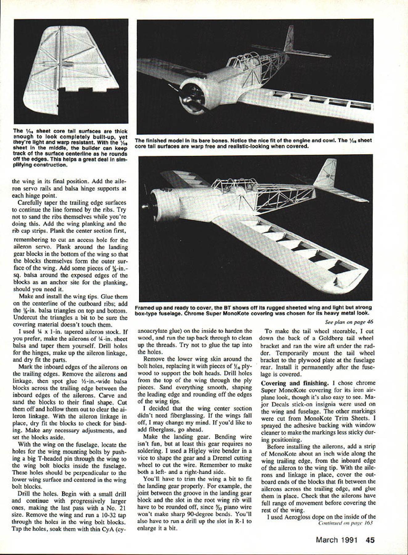

