
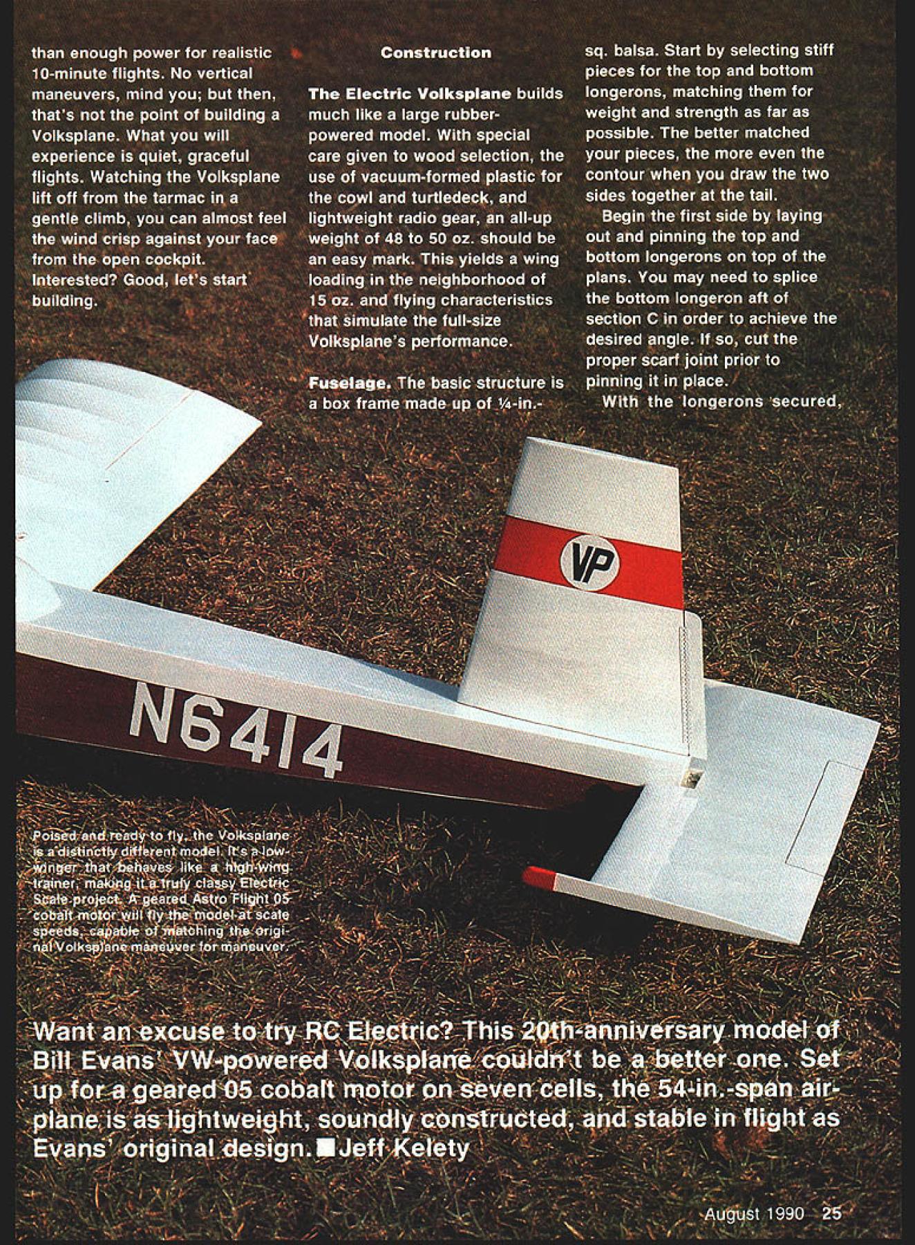
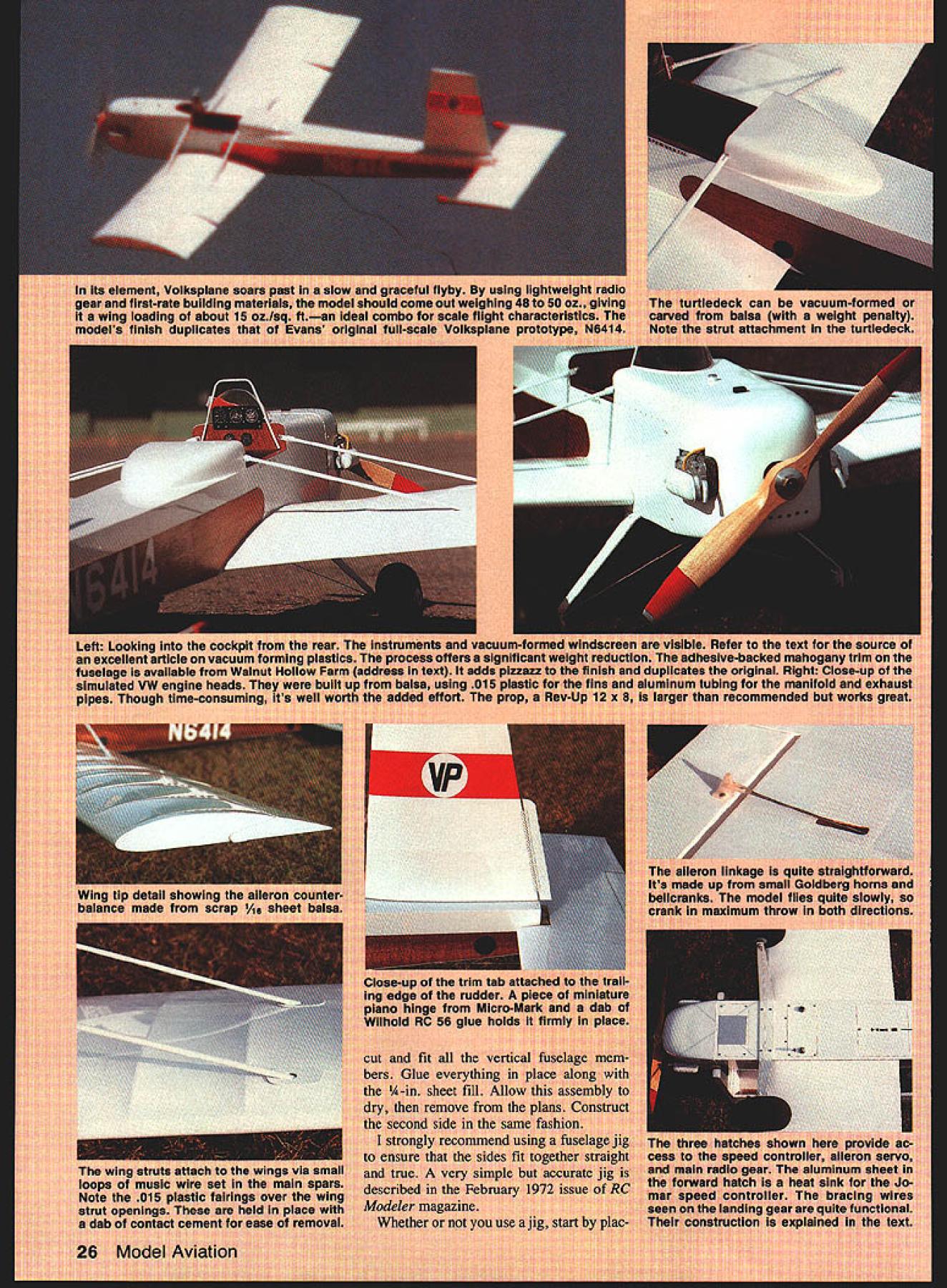
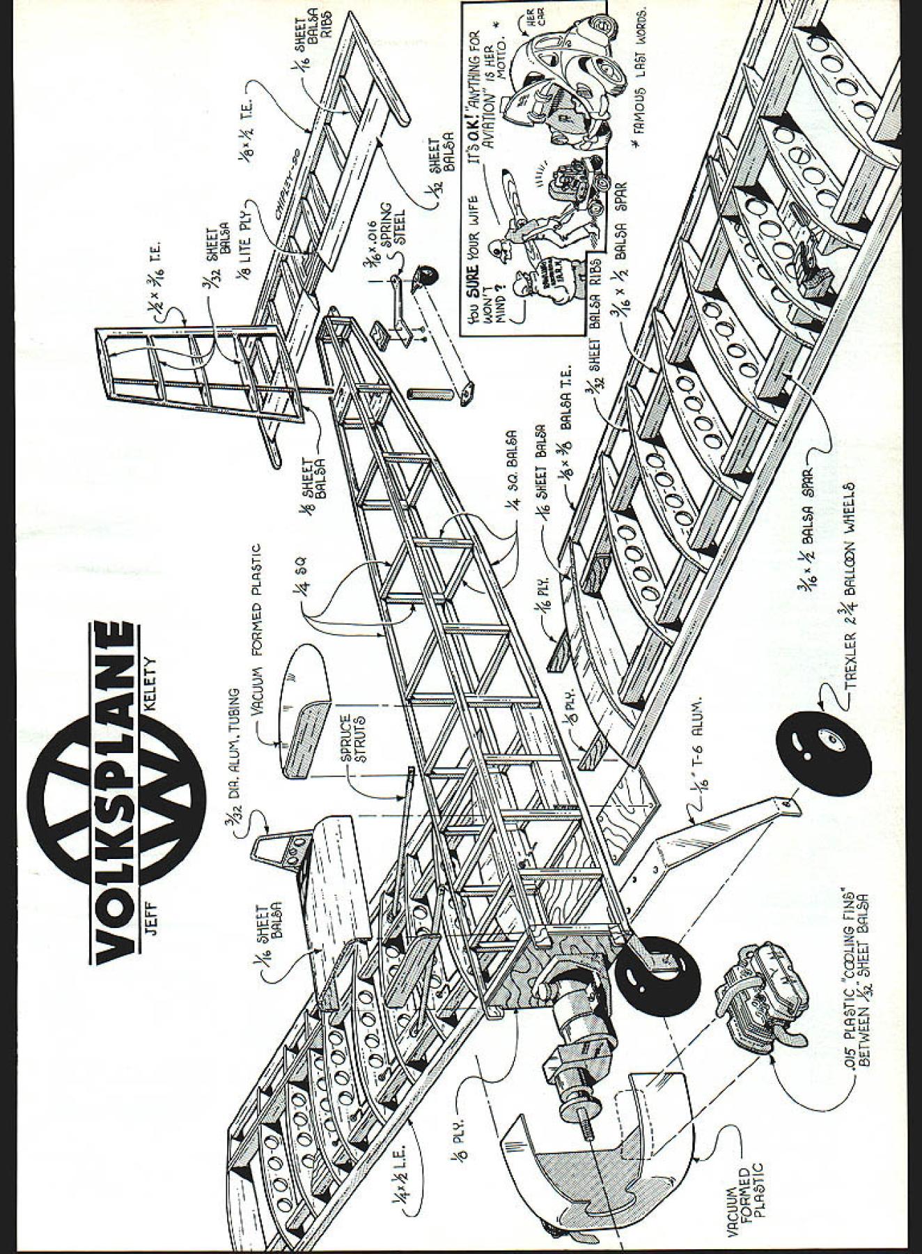
NO OCR TEXT NO OCR TEXT int Voikapian ut-rate bulidin loading ubotj finish duplicate ng ml cc Itartl4 onva avail i fran a hai I~ IT shawl flyby usin out weighing scale flight c Valkaplane ledeck can balsa utattac irar TO INS a-backed original g tar mi n recommends / K. ing 015 rt Pt aiieran made nicranks ank ml guuu uu vertic verything ii ove ti e sa commen ry Si Ipl VOl VKSP lANE JEFFKELETY DIR RLU\TUBING VACUUM FORMW PLPTIC Jf4\ CE Iiif II % SMEET 2RLP Y8 LITE PLY z REET % PLY VRGUUtA FORD PL%TIC 0I5 PL%TIC CmLING FIN8 PETWEU4 ILR 1-6RLUM 1 V4 Q RLR HEET BiLt5P J4 BRL8TE PRR TRELER 4 BILLN WHEEL rbu OPL YOUR WIFE IT5OKT NrTHING FOR RVIflTION iS HER AIOTtO ICL~ 7RI x Y2 BRLR PFIR FRMOU LRT WORD5 QXLE LE. xYz TE RIBS ing both fuselage sides upside down 900 building board Glue crosspieces section station just aft section C dry draw two sides together tail glue end crosspieces ensure straight fuselage mark 3/3201 TUBING COWLING SIDE VIEW COOLING FINS MADE FROM 015 PLASTIC SHEET SANDWICHED BETWEEN 1/32 BALSA REMAINDER IS MADE FROM BALSA AND ALUMINUM TUBE D THRUST ti ALUM L G 1/16 BALS SHEETINS A- F-S I/B BALSA SHEET F-I I/B FLY MOUNTING 74 HOLES MARKED FORI JTEC OS ELECTRICI MOTOR MOUNTI 1/16 BALSA SHEET VACUUM FORMEDA PLASTIC COWL I/B TO 2SPEED DOWN THRUSTCONTROL AREA ASTRO- FLIGHT GEARED OS COBALT MOTOR-MOUNTEDA ON JTEC ELECTRIC MOUNT I/B PLY LANDING GEAR MOUNT 77 1A6 ALUM L 0 SEE SHEET 3 FOR PATTERN centerlines end crosspieces align centerline drawn build ing board before gluing Fill remaining crosspieces glue place Before adding formers drill 3A6-dia rudder post holes run di28 Model Aviation fuselage begins take shape jig described February 1972 issue RCM makes easier build straight true fuselage However Isnt absolutely necessary close-up view Astro Flight geared 05 cobalt motor Installed firewall JTec aluminum mount direct-drive 15 cobalt motor can easily installed will probably drive Volkapiane little authority drilled tabs attaching cowling radio gear except aileron servo fits neatly fuselage bay aft section C 1A-in Lite Ply receiver-and-battery tray removable ease installation service seven-cell 1200 mAh battery pack secured floor compartment adhesive-backed Velcro strips its exact loca tion must shifted fore aft achieve correct CG center-of-gravity should 25% 30% wing chord Full-Size Plans Page 196 5/32 DIA HOLES TO ACCEPT RUDDER POST L32 PLY016 BRASS SHEET R5 INSTRUMENTSPRUCE WINGRUDDER CONTROL PANELSTRUTSHORN R-4 BUILD ACCESS HATCH FOR BATTERY PACK FROM I/B-016 BRASS SHEET BALSA SHEET-NOT SHOWN RUDDER TILLER ARM R-2 IETAI NOTE ON RUDDER RIBS R-I BALSA SHEET R-2 THRO 3/32 BALSA SHEET 3/32 OIA MUSIC WIRE 3/32 WHEEL COLLAR 7 BUILD T ASSEMBLY INTO STABILATOR FASTEN TO FR WITH2 SELF TAPPING SCREWS FUSELAGE TOP VIEW 3 B DIA HOE DACCEPT RUDDER S EERNG TUBE III C flFIII[jTORTE4S0 BALSA NOT SHOWNIIIDECKF SELAGE FRAME II II_______________________________________________ I I________ 3B SA W NG STRUTSOR BROOD HOFED NO STRUTS I/B LITE PLY TAILWHEEL MOUNT AILERONI SERVOI II I/lA NYROD ADAPTOR WITH END TAPPED N EPODIED INTO PLACE 2-SRF-4 I/B BLINDLITE PLY LYNUT TYPICALSAND TO STREAMLINES DRAPE C-CD-DNYLON WASHER I3/B WHEP REARINGE-E3/32 PLY CS AR -- R PIN DUBRO 1/2 NOSE GEAR BRACKET IER ARM SOLDERED1o--H%A MOUNTED SIDEWAYS [F-S 1/16 PLY WINGIWHEEL COLLAR BRACE BOXI RIRAEXIT FOR S/IA AD TOREPUSHROD CONTROLWIRE VA S PACER TO HORN N TAP FORFLOOR_____ SOCKET HEAD S TO SECAREVACUUM FORMED CPLASTIC TURTLE -]DECK7 TO ACCEPT UTS~ RECV/BATT AREA J RL SERVOS C--ACCESS HATCH TO RECEIVER FUSELAGE SIDE VIEW II/ 5-5 BALSA SFFEET GUSSETS 3/161/41111115 RUDDER 5/32 DIA ALUM TUBE Id rNk cT~ 7 1/2 3/16 BALSA T E STOCK GD-RHO 1/2 NOSE OEAR MOUNT STABILISTOR HORN -S/IA DIR SPRING STEEL 2-56NUTS H BOLTS USED --TOMOUNT T/W ASSEMBLY 3/4 TAILWHEEL SMALL JEWELRY SAND DOWN TO 1/2 FUSE FRAMECHAIN I034 4 PROM I/H /4 SPHUC5TOP F-5 PLY-MAAE4BOILO WINS BRACE BORES WITH I/B 55 PLY SEPARATOR /ILYSEPORATOR MAHOGANY VENEER FROM WALNUT HOLLOW FARM RURAL ROUTE 2 0 GEVILLE WI 53533 NOTCH 1/4 0 CROSS S AT B & C TO ACCEPT BRACE BOX XLER 2-3/4 DIA LOGFJ WHEELS REFERENCES EVANS W S SPORT AVIATION MAY IRAN PP SO-3S EVANS WS VP INFO HIT FROM EVANS AIRCRAFT REATY JW SPORT AVIATION APRIL INTl PP 30-33 DAVIS 0 SPORT AVIATION MARCH IBBI SPECIFICATIONS TAILWHEEL BRACKET 016 S WINO SPAN56 LENGTH -41 WEIGHT50 OZ POWERGEARED COBALT 05 SHEET MODEL AVIATION VOLKSPLANE DESIGNED BY 3EFF KELETY TRACING BY 30E DEMARCO 2 L RIGHTS m~vn rectly through center top bot tom crosspieces section D Care must taken align holes exactly 90W top fuselage ensure perfectly ver tical rudder placed fuselage upside down small drill press drilled bottom crosspiece through top Formers Fl -F6 should prepared added time Before installing formers F3 F4 drill glue 2-56 blind nuts locations indicated blind nuts will used secure wing struts fu selage Construct forward aft wing brace boxes F5 pieces forward box built A-in -sq hardwood separators aft box uses AR separators sure position wing brace boxes ex actly shown plans order en sure proper wing alignment Note will have notch bottom crosspieces slightly sections B C Locate drill mounting holes former F6 hA nose gear used attach stabila tor Add %-in balsa Lite Ply battery floor rests top wing brace boxes Sheet forward section fuse lage between formers F2 F3 AR balsa add A-in plywood supports main tail landing gear also good time install mounting sup ports radio August 1990 29 BALSA EET Seen balsa plugs right resulting vacuum-formed cowl tur tiedeck left process takes some work weight save worth effort aileron servo shown mounted bot tom wing servo mounting tape Notice two control rods con nected servo arm removing arm pin devises Complete fuselage cutting slits A-in balsa fill accept wing braces aileron pushrods Cowl turtledeck windshield Rudder components ready final assem bly Construction straightforward rud der pivots %2 aluminum main spar rudder post sleeve 3A6-in-0D brass tubing control horn tiller made 016 brass sheet Note small nylon washer acts bushing base rudder Two 6A wheel collars small cotter pin complete parts list Complete construction details plans text cowl turtledeck can made hol lowed-out balsa vacuum-formed plastic latter offers significant weight reduc tion parts can painted directly special preparation An excel lent how-to article vacuum forming offered Steve Gray March 1987 sue Model Builder Speaking cowl dont chicken out dummy VW heads valve covers make difference ones shown prototype constructed balsa 015 plastic fins aluminum tubing manifold exhaust pipes Doing right takes bit time its definitely worth end windshield can also vacuum formed An alternative make ace tate pliable heat gun stretch form over balsa mold Rudder post assembly Begin cutting control horn tiller arm 016 brass sheet Drill necessary holes cut rudder post sleeve y6-OD brass tubing rudder post %OD aluminum tubing Slip rudder post sleeve over rudder post Center drill hole just large enough accept small cotter pin through both pieces tubing position indicated Set rudder post aside later rudder assembly Solder control horn sleeve shown Solder /6 wheel collar tiller arm Cut /l6 plywood bearings drilling necessary /6 holes Carefully glue bearings crosspieces section D 1/4 1/2 BALSA3/35 BALSATOP LEADING EDGERIB 1/1 -o-i Sj SECTION B-B CENTER SECTIONPUSHROD RIB WITH SHEET INS TOP B BOTTOM SPAR WITH BRACESECTION A-A W-3 OUTLINE 1/16 BALSAN CAP STRIP TOP GOT I/B 3/IEI/B BALSA BALSASHEET 4 WIWIWI ALERON PUSHROD I/15 PLY AlL BELLCRANK MOUNTB W-I I/IS BALSA SHEET BOTTOM ONLY W-I W-I / h - TYPICAL7 HINGE LOCATION SLERON HORN I/B LITE PLY HORN MOUNT shimming up lower bearing slightly rests 900 rudder post After test ing fit set rudder post assembly aside until youre ready covering Rudder Cut out ribs Rl-R5 Mark cut out % holes locations shown plan accept rudder post Slide ribs over post making sure hole drilled earlier accept cotter pin 30 Model Aviation Looking Volkaplanes belly shows three access hatches hatchforward landing gear has aluminum speed controller heat sink piy landing gear mounting plate has lightening holes cut center hatch accesses aileron servo aft hatch accesses radio gear Control switches jacks best installed shown two smail holes just forward center hatch leading edge wing mounting bolts Above structurally complete stabilator pivoting system made up 1/aA nose gear mount length %2 music wire %2 wheel collar Right rudder pivot system shown stalled servo pushrod attached wheel collar soldered rudder sleeve secures control horn small cotter pin installed photo Dont leave out ties rudder spar control sleeve system wont work Full-Size Plans Available Page 196 3/32 BALSASHEETSLOT FOR 3/16 MAKE 181/2 BALSA SPARS ___C-1/16 BALSA DOUBLER wiMAKE 2 ___W-3 I/IS BALSA SHEET _____SHEETMAKE 2 I/IS BALSA SHEET TOP ONLY w-I WING STRUT HOOK W-23/32 BALSA MAKE 4 W-I 3/32 BALSA SHEET RIBS W-IW-2 zzrnzv-t P4 1/2 BALSA LEADING EDGE WB-I 1---- / 1/32 PLY SPAR BRACES W-I W-IW-2 z3i7 I/IS BALSA S-IEET TOP AND BOTTOM I/B 3/8 BALSA I/IS BALSA_____ I/IB PLYWOOD DOUBLERS MAKE 45-3 S-21/16 BALSA SHEET MAKE 2 s-I I/IS BALSA SHEET MAKE ID 1/16 BALSA LERS I/IS PLY WB -2 1/32 BALSA SHEET TOP ONLY W-2 3/IS SO BALSA LEADING EDGE I/ISBALSA SHEET TOP AND BOTTOM I/W BALSA WEB VERTICAL GRAIN WB-I I/B PLY -WB-I 2 FROM PLY WBI PLY 8 PLY N SERVO W-2 1/16 PLY WB-2 H / S-P S-I S-I Si S S-I BILATOR S-I S-I I/IS BALSA SHEET RIBS 2 5-2 1/32 BALSA SHEET TOP ONLY SHEET 2 OF 2 BEND BEND I/8d/2 BALSA TE STOCK LITE PLY 1/8 TOP 0 DRILL FOR AXLE I/IS TB ALUMINUM DRILL FOR CABLE LANDING GEAR PATTER N REND SHORT LENGTH OF 030 ID COPPER TUBE SOLDER TO END OF CABLE 030 CABLE BRACING FROM SULLIVAN GOLDEN RODI LANDING GEAR DETAIL 23456 MODEL AVIATION _______ VOLKSPLANE DESIGNED BY JEFF KELETY TRACING BY JOE DEMARCO ALL RIGHTS RESERVED portion post below Ri Block up leading trailing edge pieces pin place over plans Position ribs attached rud der post over plans glue entire assembly CyA cyanoacrylate Remember CyA joints between rud der post ribs Complete struc ture adding corner gussets stalling rudder sure use nylon washer bushing between rudder fuselage TRUT r cc B BALSA B EDGE W-I WING AILERON PUSI-WO7 WING WI Stabilator Block up pin leading trailing edges well bottom spar Position CyA ribs Add top spar % leading edge sheeting Drill 3/ holes shown add half ribs S3 Slip len2th music wire F close-up ins compietea tail wneei tiller Soldered bottom rudder post sleeve its connected tail wheel sembly small jewelry chains tensioned springs end just original Details stabilator pivot mechanism tail wheel V2A nose gear mount must attached ply fuselage plate before covering Tail wheel assembly details explained text Cut-and-bent straight pins serve chain attachments Stabilator tail wheel assemDlles 511 shot rigging isnt easy conventional system its closer original full-size Volksplane configura tion real eye-catcher judges August 1990 31 Left Wing ribs ready go Lightening holes cut out time using length sharpened brass tubing false ribs shown photo never usedthough lull-scale Volkaplane Right completed wing panels struts left Ailerons bellcranks linkage also complete wings form light strong structure also depend struts dont omit Left Close-up aileron belicrank assembly Hardware consists small Goldberg belicrank horn inner Nyrod pushrods Short lengths outer Nyrod glued ribs serve bearings pushrods Right complete aileron control linkage installed aileron horn mounted 1/-ln ply supports belicrank mount 1Ao plywood aileron pushrod exit sheeting As balsa tween half ribs Du-Bro /2A nose gear mount wheel collar place epoxy music wire position Fin ish stabilator adding A6 balsa web bing ballast ribs S2 Main landing gear Fashion gear /16 T6 aluminum Trexler balloon tires mounted 6-32 bolts bolts serve axles secured nuts cinched both sides gear leg Drill two holes shown accept 030 bracing wires Crimp solder /l6 Balsa USA solder lugs ends bracing wire mount lugs 632 axles Draw wire through its oppo site rigging hole leaving inch ex cess wire Solder small length 030ID tubing flush against outside side gear sure make good sol der joint since bracing wires quite functional Complete rigging cutting off excess wire Tail wheel assembly Cut tail wheel bracket 016 brass drill necessary holes bend bracket shown Sol der length %2-ID brass tubing base accept 2-56 mounting screw Use Perfect -in wheel sanded down diameter /2 mounted sembly /6-dia brad tail wheel assembly can attached fuselage length spring steel provided CB Associates small tail wheel assembly Using entire CB assem bly would save some trouble wont quite scale complete tail wheel run lengths light costume jewelry chain steel fishing leader small springs end tail wheel tiller arm Wings Begin making ribs Y32 balsa use sandwich method making two rib templates either /16 plywood thin aluminum inserting strips /32 balsa sandwiched between Use scroll saw rough cut initial shape block sand final shape Note airfoil has slight undercamber sandwich still intact drill holes accept aileron pushrods lightening holes optional youre go ing make use appropriate-diameter brass tubing sharpened edges pro duce clean holes Cut leading trailing edge pieces /z x /6 balsa spars Pin trailing edges plans Slip ribs over spars slide place glu ing Position rib/spar assemblies accu rately over plans pin down Block up pin leading edge ribs spars leading edge prop erly aligned glue everything except root ribs W2 place thin CyA Cut out wing braces using A-in ply wood WB 1 /l6 ply WB2 Tempo rarily clamp spars clothes pins Slide wings fuselage wing brace boxes test fit wings fuselage block up wing tip 2 building board scrap balsa Remove wings fuselage un clamp wing braces reattach slow-drying glue such Elmers wood glue Quickly reposition wing braces clothespins wings rest against scrap balsa braces Doublecheck make sure have 2 /2 dihe dral under tip adjust needed Note bottom wings should rest e bottom fuselage dry position glue ribs flush against fuselage Remove wings add remaining root sheeting construct ailerons separate 32 Model Aviation Clue up ui wing urcus unu wiurn pushrod exiting wing Note male arm removed clevis wing small nut locks clevis place Left four completed wing struts Theyre finished white rryion spray paint hooked end fits wing paneis Right Ciose-up wing struts attached wing paneis hooks end struts attach wire ioops buiit main spars Length can adjusted screwing hooks out necessary achieve correct fit tension struts exit panels balsa sheet necessary ribs rear spar shown using sharp razor blade Make neces sary separation trailing edge well Cut aileron ribs proper angle add %-in balsa aileron backplates Use scrap A6 balsa evenly build up top bottom surfaces rear spar aileron ribs cut away Finish adding aileron bellcrank assembly along pushrods used inner portion Nyrods aileron pushrods save weight cut A-in lengths outer Nyrods guides glued place rib Small loops 047 music wire inserted glued spars shown serve attaching struts wings sure add A2 plywood spar brace reinforce spar sections Wing lock screws wings held place using 2-56 x A-in socket-head screws set / forward wing brace box Begin inserting both wings fuselage making sure flush Drill tap 2-56 hole forward wing brace box shown section B-B Countersink holes balsa crosspiece tops screws flush -with bottom fuselage 2-56 screws should hold wings firmly place sloppiness fly wing lock screws Wing struts Cut fuselage joining brack ets 016 brass sheet Drill holes shown Cut four struts / x A-in spruce Using razor saw cut slits accept brackets other end struts drill tap 2-56 holes accept wing joining hook Fabricate hooks 2-56 threaded rod Sand struts streamlined cross section check fit against fuselage CyA fuselage joining brackets place Finally adjust fit struts screwing wing hooks proper depth CyA hooks place Use roundheaded 2-56 screws attach struts blind nuts formers F3 F4 Radio installation Microservos lightweight receiver 250-mAh battery adequate direct Volks plane prototype battery re ceiver secured rubberbands tray made %-in Lite Ply receiver tray secured #2 screws strips A-in Lite Ply glued fuselage just aft section C elevator rudder servos also placed area Access radio gear via hatch constructed bottom fuselage elevator Continued page 106 August 1990 33 Left Front view compieted frame ins vacuum-formed cowi attacneo witn small Perreci wooa screws jo ply tabs giueu iu Inc Iruww. Trexier 2-in bailoon tires recommended Right cockpit area showing strut attachment points instruments windscreen frame Volkapiane its bare bones ready covering detailing aii lightening holes shown using white MonoKote weighs about much Guiliow rubber-powered kit Volksplane/Kelety Continued page 33 rudder pushrods made A-in balsa should installed prior cover ing aileron servo installed bot torn battery floor aft section B using servo mount ing tape sure coat balsa area receiving mount ing tape CyA sealing grain Construct second hatch loca tion access servo Covering fin ishing White Mono Kote used prototype model throughout Follow sequence wish except rudder should covered before fuselage covering fuselage begin sides pro ceed top bottom still open install rudder rudder post assembly rudder pushrod Make sure cot ter pin secure tiller arm firmly place youre satis fied rudder secure cover fuselage bottom used Krylon gloss white spray cowl turtledeck struts landing gear wood trim fuselage sides adhesivebacked mahogany veneer Wal nut Hollow Farm Rural Route 2 Dodgeville WI 53533 given several hand coats clear-gloss polyurethane Regis tration numbers remaining trim cut scrap MonoKote ironed place lettering Experimental sides cockpit adhesivebacked clear tape produced Merlin Lettering System can usually find local photocopy centers. Final assembly Attach windshield cowl using Wilhold R/G 56 like Complete cockpit desired attach cowl Attach main tail landing gear install stabilator aileron pushrod devises overlap attach single hole servo arm used Du-Bro metal Kwik-Links male arm two aileron links re moved permits remaining female arm held place overlapping male arm other clevis securing motor battery pack rec ommend using adhesive-backed Velcro Coat battery floor CyA attach side Velcro attach other side battery pack havnt already done prepare wing attachment cutting slits turtledeck forward fuselage sheeting ac cept wing struts Very carefully slide wing panels fuselage Remem ber both struts aileron pushrods must inserted respective slots Connect devises aileron servo arm cinch down access hatch youre business As prop size start Rev-Up 12 x 8 bit larger 11 x 7 Astro Flight recommends geared 05 motor can easily handle added pull prop greatly enhances performance air Flying Volks plane should balance 25% 30% hind leading edge Adjust motor battery posi tion needed achieve proper CG center-of-grav ity Check re check fit tings test control surface movements motor running Ad just ailerons maximum throw possible start ers set elevator no up/down deflec tion everything checks out turn Volksplane wind smoothly apply throt tle prepared apply little right rudder counter act natural P-fac tor takeoff isnt fast ship dont try force off ground tempt anything yond gentle climb out Once air can expect sta ble scalelike per formance havent tried aerobatics yetit after Volksplane loops ought no problem following shallow dive rolls strap cobalt 15 Land ings best accomplished just bit throttle control control quite graceful Flying two-thirds throttle plenty power scalelike performance Continued page 115 106 Model Aviation Volksplane/KeletyW 4 PTU Continued page 106 model easily sustains eight-to 10-minute flights its competition debut years San Louis Obispo Electrifest Volksplane took first place Sport Scalenot bad its first time out youve thought joiningor already have joinedthe quiet revolution Volksplane great Elec tric build CL Navy Carrier/Perry Continued page 71 widely accepted Denver Rules can obtained sending stamped envelope Members some Midwest Control Line clubs will sponsor 15 Carrier event Sig Skyray Carrier Sig Manufacturing Company sponsoring unofficial Carrier event its Skyray 35 model Ive discussed Skyray Carrier event previous columns will no restrictions entry Details event can obtained Sig sending stamped envelope return address Eugene Ely Award another part Nats made possible Navy Carrier Society perpetual award recognizes outstanding competitor three Carrier events Nats winner determined adding official scores three official Nats Carrier events Profile Class Class II flier having greatest total score being win ner individual award consists en graved silver platter presented annual dinner meeting Navy Carrier Society dur ing Nats Rookie Year Award also being sponsored NCS will go contestant new Nats Carrier competition award will subjective based perform ance participation sportsmanship other fac tors deemed appropriate sponsors Sterling Models update just received letter Tom Haldis describing recent changes Sterling Tom new president com pany now bears name Sterling Hob bies Incorporated may have disappointed Sterling kits last few years will happy hear Toms efforts improve quality materials work manship paying off Ive just examined Sterlings newly reis sued F6F Hellcat kits found good quality wood excellent die cutting Hellcat has 42-in span about 360 sq wing area can easily converted competition Pro file Carrier Im glad see available again Two other kits P-Si Mustang Yak-9 converts Airabonita Scale bonus points should have completed new production run time issue reaches hands Both kits have wing areas just above 300 sq August 1990 115 PSS GLIDER $17500 WINGSPAN52 SCALE FUSELAGE42 AIRFOILMOD EPPLER 206 WEIGHT48 OZ MATERIALS FUSELAGE POLYESTER GLASS AND CARBON FIBER WING FOAM CORE WITH BALSA SHEETING U STABILIZER FOAM CORE WITH BALSA SHEETING HUNTV CANOPY FRAME POLYESTER GLASS ODEL AIRPLANES CANOPY FORMED BUTYRATE4960 BUTtERNUT TRAIL AU WI 63039 TIP TANKS $1500 EXTRA POLYESTER GLASS 4 349-6101 PAYDIRT 60 Serious About Performance Symmetrical70-91 4-C 60 Inch Wing50-61 2-C 800 Squares7-8 LBS See local dealer first. Additional formation Available_____ .We know want flyl 1731 NW Madrid Way Boca Raton FL 33432 407-367-7744 SAFE -T- DAMPER PROVEN TRUE DAMPING ACTION NOT SNAP OFF $ 995FUEL PROOF ORDER TOLL FREE-462-2940 ICROERI ONLY RRAS1 WE HONOR ALL MAJOR CREDIT CARDS CODS CHECKS OR MONEY ORDERS ACCEPTED FLATS 250 POSTAGE AND HANDLING CHARGE PER ORDER UP TO 6 SETS [R INQUIRY INVED 2631 NW 20th St. Miami Florida 33142 HOBBYTECH INCPH 305 638-9439 305 6337183 responding advertisers mention read about Model Aviation

Edition: Model Aviation - 1990/08
Page Numbers: 24, 25, 26, 27, 28, 29, 30, 31, 32, 33, 106, 115
Edition: Model Aviation - 1990/08
Page Numbers: 24, 25, 26, 27, 28, 29, 30, 31, 32, 33, 106, 115
NO OCR TEXT NO OCR TEXT int Voikapian ut-rate bulidin loading ubotj finish duplicate ng ml cc Itartl4 onva avail i fran a hai I~ IT shawl flyby usin out weighing scale flight c Valkaplane ledeck can balsa utattac irar TO INS a-backed original g tar mi n recommends / K. ing 015 rt Pt aiieran made nicranks ank ml guuu uu vertic verything ii ove ti e sa commen ry Si Ipl VOl VKSP lANE JEFFKELETY DIR RLU\TUBING VACUUM FORMW PLPTIC Jf4\ CE Iiif II % SMEET 2RLP Y8 LITE PLY z REET % PLY VRGUUtA FORD PL%TIC 0I5 PL%TIC CmLING FIN8 PETWEU4 ILR 1-6RLUM 1 V4 Q RLR HEET BiLt5P J4 BRL8TE PRR TRELER 4 BILLN WHEEL rbu OPL YOUR WIFE IT5OKT NrTHING FOR RVIflTION iS HER AIOTtO ICL~ 7RI x Y2 BRLR PFIR FRMOU LRT WORD5 QXLE LE. xYz TE RIBS ing both fuselage sides upside down 900 building board Glue crosspieces section station just aft section C dry draw two sides together tail glue end crosspieces ensure straight fuselage mark 3/3201 TUBING COWLING SIDE VIEW COOLING FINS MADE FROM 015 PLASTIC SHEET SANDWICHED BETWEEN 1/32 BALSA REMAINDER IS MADE FROM BALSA AND ALUMINUM TUBE D THRUST ti ALUM L G 1/16 BALS SHEETINS A- F-S I/B BALSA SHEET F-I I/B FLY MOUNTING 74 HOLES MARKED FORI JTEC OS ELECTRICI MOTOR MOUNTI 1/16 BALSA SHEET VACUUM FORMEDA PLASTIC COWL I/B TO 2SPEED DOWN THRUSTCONTROL AREA ASTRO- FLIGHT GEARED OS COBALT MOTOR-MOUNTEDA ON JTEC ELECTRIC MOUNT I/B PLY LANDING GEAR MOUNT 77 1A6 ALUM L 0 SEE SHEET 3 FOR PATTERN centerlines end crosspieces align centerline drawn build ing board before gluing Fill remaining crosspieces glue place Before adding formers drill 3A6-dia rudder post holes run di28 Model Aviation fuselage begins take shape jig described February 1972 issue RCM makes easier build straight true fuselage However Isnt absolutely necessary close-up view Astro Flight geared 05 cobalt motor Installed firewall JTec aluminum mount direct-drive 15 cobalt motor can easily installed will probably drive Volkapiane little authority drilled tabs attaching cowling radio gear except aileron servo fits neatly fuselage bay aft section C 1A-in Lite Ply receiver-and-battery tray removable ease installation service seven-cell 1200 mAh battery pack secured floor compartment adhesive-backed Velcro strips its exact loca tion must shifted fore aft achieve correct CG center-of-gravity should 25% 30% wing chord Full-Size Plans Page 196 5/32 DIA HOLES TO ACCEPT RUDDER POST L32 PLY016 BRASS SHEET R5 INSTRUMENTSPRUCE WINGRUDDER CONTROL PANELSTRUTSHORN R-4 BUILD ACCESS HATCH FOR BATTERY PACK FROM I/B-016 BRASS SHEET BALSA SHEET-NOT SHOWN RUDDER TILLER ARM R-2 IETAI NOTE ON RUDDER RIBS R-I BALSA SHEET R-2 THRO 3/32 BALSA SHEET 3/32 OIA MUSIC WIRE 3/32 WHEEL COLLAR 7 BUILD T ASSEMBLY INTO STABILATOR FASTEN TO FR WITH2 SELF TAPPING SCREWS FUSELAGE TOP VIEW 3 B DIA HOE DACCEPT RUDDER S EERNG TUBE III C flFIII[jTORTE4S0 BALSA NOT SHOWNIIIDECKF SELAGE FRAME II II_______________________________________________ I I________ 3B SA W NG STRUTSOR BROOD HOFED NO STRUTS I/B LITE PLY TAILWHEEL MOUNT AILERONI SERVOI II I/lA NYROD ADAPTOR WITH END TAPPED N EPODIED INTO PLACE 2-SRF-4 I/B BLINDLITE PLY LYNUT TYPICALSAND TO STREAMLINES DRAPE C-CD-DNYLON WASHER I3/B WHEP REARINGE-E3/32 PLY CS AR -- R PIN DUBRO 1/2 NOSE GEAR BRACKET IER ARM SOLDERED1o--H%A MOUNTED SIDEWAYS [F-S 1/16 PLY WINGIWHEEL COLLAR BRACE BOXI RIRAEXIT FOR S/IA AD TOREPUSHROD CONTROLWIRE VA S PACER TO HORN N TAP FORFLOOR_____ SOCKET HEAD S TO SECAREVACUUM FORMED CPLASTIC TURTLE -]DECK7 TO ACCEPT UTS~ RECV/BATT AREA J RL SERVOS C--ACCESS HATCH TO RECEIVER FUSELAGE SIDE VIEW II/ 5-5 BALSA SFFEET GUSSETS 3/161/41111115 RUDDER 5/32 DIA ALUM TUBE Id rNk cT~ 7 1/2 3/16 BALSA T E STOCK GD-RHO 1/2 NOSE OEAR MOUNT STABILISTOR HORN -S/IA DIR SPRING STEEL 2-56NUTS H BOLTS USED --TOMOUNT T/W ASSEMBLY 3/4 TAILWHEEL SMALL JEWELRY SAND DOWN TO 1/2 FUSE FRAMECHAIN I034 4 PROM I/H /4 SPHUC5TOP F-5 PLY-MAAE4BOILO WINS BRACE BORES WITH I/B 55 PLY SEPARATOR /ILYSEPORATOR MAHOGANY VENEER FROM WALNUT HOLLOW FARM RURAL ROUTE 2 0 GEVILLE WI 53533 NOTCH 1/4 0 CROSS S AT B & C TO ACCEPT BRACE BOX XLER 2-3/4 DIA LOGFJ WHEELS REFERENCES EVANS W S SPORT AVIATION MAY IRAN PP SO-3S EVANS WS VP INFO HIT FROM EVANS AIRCRAFT REATY JW SPORT AVIATION APRIL INTl PP 30-33 DAVIS 0 SPORT AVIATION MARCH IBBI SPECIFICATIONS TAILWHEEL BRACKET 016 S WINO SPAN56 LENGTH -41 WEIGHT50 OZ POWERGEARED COBALT 05 SHEET MODEL AVIATION VOLKSPLANE DESIGNED BY 3EFF KELETY TRACING BY 30E DEMARCO 2 L RIGHTS m~vn rectly through center top bot tom crosspieces section D Care must taken align holes exactly 90W top fuselage ensure perfectly ver tical rudder placed fuselage upside down small drill press drilled bottom crosspiece through top Formers Fl -F6 should prepared added time Before installing formers F3 F4 drill glue 2-56 blind nuts locations indicated blind nuts will used secure wing struts fu selage Construct forward aft wing brace boxes F5 pieces forward box built A-in -sq hardwood separators aft box uses AR separators sure position wing brace boxes ex actly shown plans order en sure proper wing alignment Note will have notch bottom crosspieces slightly sections B C Locate drill mounting holes former F6 hA nose gear used attach stabila tor Add %-in balsa Lite Ply battery floor rests top wing brace boxes Sheet forward section fuse lage between formers F2 F3 AR balsa add A-in plywood supports main tail landing gear also good time install mounting sup ports radio August 1990 29 BALSA EET Seen balsa plugs right resulting vacuum-formed cowl tur tiedeck left process takes some work weight save worth effort aileron servo shown mounted bot tom wing servo mounting tape Notice two control rods con nected servo arm removing arm pin devises Complete fuselage cutting slits A-in balsa fill accept wing braces aileron pushrods Cowl turtledeck windshield Rudder components ready final assem bly Construction straightforward rud der pivots %2 aluminum main spar rudder post sleeve 3A6-in-0D brass tubing control horn tiller made 016 brass sheet Note small nylon washer acts bushing base rudder Two 6A wheel collars small cotter pin complete parts list Complete construction details plans text cowl turtledeck can made hol lowed-out balsa vacuum-formed plastic latter offers significant weight reduc tion parts can painted directly special preparation An excel lent how-to article vacuum forming offered Steve Gray March 1987 sue Model Builder Speaking cowl dont chicken out dummy VW heads valve covers make difference ones shown prototype constructed balsa 015 plastic fins aluminum tubing manifold exhaust pipes Doing right takes bit time its definitely worth end windshield can also vacuum formed An alternative make ace tate pliable heat gun stretch form over balsa mold Rudder post assembly Begin cutting control horn tiller arm 016 brass sheet Drill necessary holes cut rudder post sleeve y6-OD brass tubing rudder post %OD aluminum tubing Slip rudder post sleeve over rudder post Center drill hole just large enough accept small cotter pin through both pieces tubing position indicated Set rudder post aside later rudder assembly Solder control horn sleeve shown Solder /6 wheel collar tiller arm Cut /l6 plywood bearings drilling necessary /6 holes Carefully glue bearings crosspieces section D 1/4 1/2 BALSA3/35 BALSATOP LEADING EDGERIB 1/1 -o-i Sj SECTION B-B CENTER SECTIONPUSHROD RIB WITH SHEET INS TOP B BOTTOM SPAR WITH BRACESECTION A-A W-3 OUTLINE 1/16 BALSAN CAP STRIP TOP GOT I/B 3/IEI/B BALSA BALSASHEET 4 WIWIWI ALERON PUSHROD I/15 PLY AlL BELLCRANK MOUNTB W-I I/IS BALSA SHEET BOTTOM ONLY W-I W-I / h - TYPICAL7 HINGE LOCATION SLERON HORN I/B LITE PLY HORN MOUNT shimming up lower bearing slightly rests 900 rudder post After test ing fit set rudder post assembly aside until youre ready covering Rudder Cut out ribs Rl-R5 Mark cut out % holes locations shown plan accept rudder post Slide ribs over post making sure hole drilled earlier accept cotter pin 30 Model Aviation Looking Volkaplanes belly shows three access hatches hatchforward landing gear has aluminum speed controller heat sink piy landing gear mounting plate has lightening holes cut center hatch accesses aileron servo aft hatch accesses radio gear Control switches jacks best installed shown two smail holes just forward center hatch leading edge wing mounting bolts Above structurally complete stabilator pivoting system made up 1/aA nose gear mount length %2 music wire %2 wheel collar Right rudder pivot system shown stalled servo pushrod attached wheel collar soldered rudder sleeve secures control horn small cotter pin installed photo Dont leave out ties rudder spar control sleeve system wont work Full-Size Plans Available Page 196 3/32 BALSASHEETSLOT FOR 3/16 MAKE 181/2 BALSA SPARS ___C-1/16 BALSA DOUBLER wiMAKE 2 ___W-3 I/IS BALSA SHEET _____SHEETMAKE 2 I/IS BALSA SHEET TOP ONLY w-I WING STRUT HOOK W-23/32 BALSA MAKE 4 W-I 3/32 BALSA SHEET RIBS W-IW-2 zzrnzv-t P4 1/2 BALSA LEADING EDGE WB-I 1---- / 1/32 PLY SPAR BRACES W-I W-IW-2 z3i7 I/IS BALSA S-IEET TOP AND BOTTOM I/B 3/8 BALSA I/IS BALSA_____ I/IB PLYWOOD DOUBLERS MAKE 45-3 S-21/16 BALSA SHEET MAKE 2 s-I I/IS BALSA SHEET MAKE ID 1/16 BALSA LERS I/IS PLY WB -2 1/32 BALSA SHEET TOP ONLY W-2 3/IS SO BALSA LEADING EDGE I/ISBALSA SHEET TOP AND BOTTOM I/W BALSA WEB VERTICAL GRAIN WB-I I/B PLY -WB-I 2 FROM PLY WBI PLY 8 PLY N SERVO W-2 1/16 PLY WB-2 H / S-P S-I S-I Si S S-I BILATOR S-I S-I I/IS BALSA SHEET RIBS 2 5-2 1/32 BALSA SHEET TOP ONLY SHEET 2 OF 2 BEND BEND I/8d/2 BALSA TE STOCK LITE PLY 1/8 TOP 0 DRILL FOR AXLE I/IS TB ALUMINUM DRILL FOR CABLE LANDING GEAR PATTER N REND SHORT LENGTH OF 030 ID COPPER TUBE SOLDER TO END OF CABLE 030 CABLE BRACING FROM SULLIVAN GOLDEN RODI LANDING GEAR DETAIL 23456 MODEL AVIATION _______ VOLKSPLANE DESIGNED BY JEFF KELETY TRACING BY JOE DEMARCO ALL RIGHTS RESERVED portion post below Ri Block up leading trailing edge pieces pin place over plans Position ribs attached rud der post over plans glue entire assembly CyA cyanoacrylate Remember CyA joints between rud der post ribs Complete struc ture adding corner gussets stalling rudder sure use nylon washer bushing between rudder fuselage TRUT r cc B BALSA B EDGE W-I WING AILERON PUSI-WO7 WING WI Stabilator Block up pin leading trailing edges well bottom spar Position CyA ribs Add top spar % leading edge sheeting Drill 3/ holes shown add half ribs S3 Slip len2th music wire F close-up ins compietea tail wneei tiller Soldered bottom rudder post sleeve its connected tail wheel sembly small jewelry chains tensioned springs end just original Details stabilator pivot mechanism tail wheel V2A nose gear mount must attached ply fuselage plate before covering Tail wheel assembly details explained text Cut-and-bent straight pins serve chain attachments Stabilator tail wheel assemDlles 511 shot rigging isnt easy conventional system its closer original full-size Volksplane configura tion real eye-catcher judges August 1990 31 Left Wing ribs ready go Lightening holes cut out time using length sharpened brass tubing false ribs shown photo never usedthough lull-scale Volkaplane Right completed wing panels struts left Ailerons bellcranks linkage also complete wings form light strong structure also depend struts dont omit Left Close-up aileron belicrank assembly Hardware consists small Goldberg belicrank horn inner Nyrod pushrods Short lengths outer Nyrod glued ribs serve bearings pushrods Right complete aileron control linkage installed aileron horn mounted 1/-ln ply supports belicrank mount 1Ao plywood aileron pushrod exit sheeting As balsa tween half ribs Du-Bro /2A nose gear mount wheel collar place epoxy music wire position Fin ish stabilator adding A6 balsa web bing ballast ribs S2 Main landing gear Fashion gear /16 T6 aluminum Trexler balloon tires mounted 6-32 bolts bolts serve axles secured nuts cinched both sides gear leg Drill two holes shown accept 030 bracing wires Crimp solder /l6 Balsa USA solder lugs ends bracing wire mount lugs 632 axles Draw wire through its oppo site rigging hole leaving inch ex cess wire Solder small length 030ID tubing flush against outside side gear sure make good sol der joint since bracing wires quite functional Complete rigging cutting off excess wire Tail wheel assembly Cut tail wheel bracket 016 brass drill necessary holes bend bracket shown Sol der length %2-ID brass tubing base accept 2-56 mounting screw Use Perfect -in wheel sanded down diameter /2 mounted sembly /6-dia brad tail wheel assembly can attached fuselage length spring steel provided CB Associates small tail wheel assembly Using entire CB assem bly would save some trouble wont quite scale complete tail wheel run lengths light costume jewelry chain steel fishing leader small springs end tail wheel tiller arm Wings Begin making ribs Y32 balsa use sandwich method making two rib templates either /16 plywood thin aluminum inserting strips /32 balsa sandwiched between Use scroll saw rough cut initial shape block sand final shape Note airfoil has slight undercamber sandwich still intact drill holes accept aileron pushrods lightening holes optional youre go ing make use appropriate-diameter brass tubing sharpened edges pro duce clean holes Cut leading trailing edge pieces /z x /6 balsa spars Pin trailing edges plans Slip ribs over spars slide place glu ing Position rib/spar assemblies accu rately over plans pin down Block up pin leading edge ribs spars leading edge prop erly aligned glue everything except root ribs W2 place thin CyA Cut out wing braces using A-in ply wood WB 1 /l6 ply WB2 Tempo rarily clamp spars clothes pins Slide wings fuselage wing brace boxes test fit wings fuselage block up wing tip 2 building board scrap balsa Remove wings fuselage un clamp wing braces reattach slow-drying glue such Elmers wood glue Quickly reposition wing braces clothespins wings rest against scrap balsa braces Doublecheck make sure have 2 /2 dihe dral under tip adjust needed Note bottom wings should rest e bottom fuselage dry position glue ribs flush against fuselage Remove wings add remaining root sheeting construct ailerons separate 32 Model Aviation Clue up ui wing urcus unu wiurn pushrod exiting wing Note male arm removed clevis wing small nut locks clevis place Left four completed wing struts Theyre finished white rryion spray paint hooked end fits wing paneis Right Ciose-up wing struts attached wing paneis hooks end struts attach wire ioops buiit main spars Length can adjusted screwing hooks out necessary achieve correct fit tension struts exit panels balsa sheet necessary ribs rear spar shown using sharp razor blade Make neces sary separation trailing edge well Cut aileron ribs proper angle add %-in balsa aileron backplates Use scrap A6 balsa evenly build up top bottom surfaces rear spar aileron ribs cut away Finish adding aileron bellcrank assembly along pushrods used inner portion Nyrods aileron pushrods save weight cut A-in lengths outer Nyrods guides glued place rib Small loops 047 music wire inserted glued spars shown serve attaching struts wings sure add A2 plywood spar brace reinforce spar sections Wing lock screws wings held place using 2-56 x A-in socket-head screws set / forward wing brace box Begin inserting both wings fuselage making sure flush Drill tap 2-56 hole forward wing brace box shown section B-B Countersink holes balsa crosspiece tops screws flush -with bottom fuselage 2-56 screws should hold wings firmly place sloppiness fly wing lock screws Wing struts Cut fuselage joining brack ets 016 brass sheet Drill holes shown Cut four struts / x A-in spruce Using razor saw cut slits accept brackets other end struts drill tap 2-56 holes accept wing joining hook Fabricate hooks 2-56 threaded rod Sand struts streamlined cross section check fit against fuselage CyA fuselage joining brackets place Finally adjust fit struts screwing wing hooks proper depth CyA hooks place Use roundheaded 2-56 screws attach struts blind nuts formers F3 F4 Radio installation Microservos lightweight receiver 250-mAh battery adequate direct Volks plane prototype battery re ceiver secured rubberbands tray made %-in Lite Ply receiver tray secured #2 screws strips A-in Lite Ply glued fuselage just aft section C elevator rudder servos also placed area Access radio gear via hatch constructed bottom fuselage elevator Continued page 106 August 1990 33 Left Front view compieted frame ins vacuum-formed cowi attacneo witn small Perreci wooa screws jo ply tabs giueu iu Inc Iruww. Trexier 2-in bailoon tires recommended Right cockpit area showing strut attachment points instruments windscreen frame Volkapiane its bare bones ready covering detailing aii lightening holes shown using white MonoKote weighs about much Guiliow rubber-powered kit Volksplane/Kelety Continued page 33 rudder pushrods made A-in balsa should installed prior cover ing aileron servo installed bot torn battery floor aft section B using servo mount ing tape sure coat balsa area receiving mount ing tape CyA sealing grain Construct second hatch loca tion access servo Covering fin ishing White Mono Kote used prototype model throughout Follow sequence wish except rudder should covered before fuselage covering fuselage begin sides pro ceed top bottom still open install rudder rudder post assembly rudder pushrod Make sure cot ter pin secure tiller arm firmly place youre satis fied rudder secure cover fuselage bottom used Krylon gloss white spray cowl turtledeck struts landing gear wood trim fuselage sides adhesivebacked mahogany veneer Wal nut Hollow Farm Rural Route 2 Dodgeville WI 53533 given several hand coats clear-gloss polyurethane Regis tration numbers remaining trim cut scrap MonoKote ironed place lettering Experimental sides cockpit adhesivebacked clear tape produced Merlin Lettering System can usually find local photocopy centers. Final assembly Attach windshield cowl using Wilhold R/G 56 like Complete cockpit desired attach cowl Attach main tail landing gear install stabilator aileron pushrod devises overlap attach single hole servo arm used Du-Bro metal Kwik-Links male arm two aileron links re moved permits remaining female arm held place overlapping male arm other clevis securing motor battery pack rec ommend using adhesive-backed Velcro Coat battery floor CyA attach side Velcro attach other side battery pack havnt already done prepare wing attachment cutting slits turtledeck forward fuselage sheeting ac cept wing struts Very carefully slide wing panels fuselage Remem ber both struts aileron pushrods must inserted respective slots Connect devises aileron servo arm cinch down access hatch youre business As prop size start Rev-Up 12 x 8 bit larger 11 x 7 Astro Flight recommends geared 05 motor can easily handle added pull prop greatly enhances performance air Flying Volks plane should balance 25% 30% hind leading edge Adjust motor battery posi tion needed achieve proper CG center-of-grav ity Check re check fit tings test control surface movements motor running Ad just ailerons maximum throw possible start ers set elevator no up/down deflec tion everything checks out turn Volksplane wind smoothly apply throt tle prepared apply little right rudder counter act natural P-fac tor takeoff isnt fast ship dont try force off ground tempt anything yond gentle climb out Once air can expect sta ble scalelike per formance havent tried aerobatics yetit after Volksplane loops ought no problem following shallow dive rolls strap cobalt 15 Land ings best accomplished just bit throttle control control quite graceful Flying two-thirds throttle plenty power scalelike performance Continued page 115 106 Model Aviation Volksplane/KeletyW 4 PTU Continued page 106 model easily sustains eight-to 10-minute flights its competition debut years San Louis Obispo Electrifest Volksplane took first place Sport Scalenot bad its first time out youve thought joiningor already have joinedthe quiet revolution Volksplane great Elec tric build CL Navy Carrier/Perry Continued page 71 widely accepted Denver Rules can obtained sending stamped envelope Members some Midwest Control Line clubs will sponsor 15 Carrier event Sig Skyray Carrier Sig Manufacturing Company sponsoring unofficial Carrier event its Skyray 35 model Ive discussed Skyray Carrier event previous columns will no restrictions entry Details event can obtained Sig sending stamped envelope return address Eugene Ely Award another part Nats made possible Navy Carrier Society perpetual award recognizes outstanding competitor three Carrier events Nats winner determined adding official scores three official Nats Carrier events Profile Class Class II flier having greatest total score being win ner individual award consists en graved silver platter presented annual dinner meeting Navy Carrier Society dur ing Nats Rookie Year Award also being sponsored NCS will go contestant new Nats Carrier competition award will subjective based perform ance participation sportsmanship other fac tors deemed appropriate sponsors Sterling Models update just received letter Tom Haldis describing recent changes Sterling Tom new president com pany now bears name Sterling Hob bies Incorporated may have disappointed Sterling kits last few years will happy hear Toms efforts improve quality materials work manship paying off Ive just examined Sterlings newly reis sued F6F Hellcat kits found good quality wood excellent die cutting Hellcat has 42-in span about 360 sq wing area can easily converted competition Pro file Carrier Im glad see available again Two other kits P-Si Mustang Yak-9 converts Airabonita Scale bonus points should have completed new production run time issue reaches hands Both kits have wing areas just above 300 sq August 1990 115 PSS GLIDER $17500 WINGSPAN52 SCALE FUSELAGE42 AIRFOILMOD EPPLER 206 WEIGHT48 OZ MATERIALS FUSELAGE POLYESTER GLASS AND CARBON FIBER WING FOAM CORE WITH BALSA SHEETING U STABILIZER FOAM CORE WITH BALSA SHEETING HUNTV CANOPY FRAME POLYESTER GLASS ODEL AIRPLANES CANOPY FORMED BUTYRATE4960 BUTtERNUT TRAIL AU WI 63039 TIP TANKS $1500 EXTRA POLYESTER GLASS 4 349-6101 PAYDIRT 60 Serious About Performance Symmetrical70-91 4-C 60 Inch Wing50-61 2-C 800 Squares7-8 LBS See local dealer first. Additional formation Available_____ .We know want flyl 1731 NW Madrid Way Boca Raton FL 33432 407-367-7744 SAFE -T- DAMPER PROVEN TRUE DAMPING ACTION NOT SNAP OFF $ 995FUEL PROOF ORDER TOLL FREE-462-2940 ICROERI ONLY RRAS1 WE HONOR ALL MAJOR CREDIT CARDS CODS CHECKS OR MONEY ORDERS ACCEPTED FLATS 250 POSTAGE AND HANDLING CHARGE PER ORDER UP TO 6 SETS [R INQUIRY INVED 2631 NW 20th St. Miami Florida 33142 HOBBYTECH INCPH 305 638-9439 305 6337183 responding advertisers mention read about Model Aviation
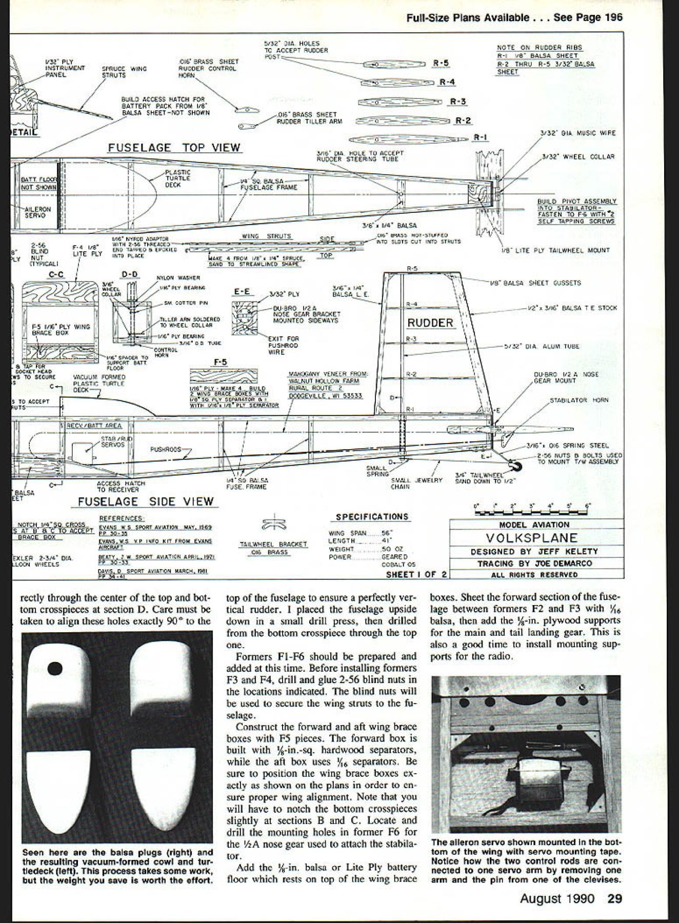

