
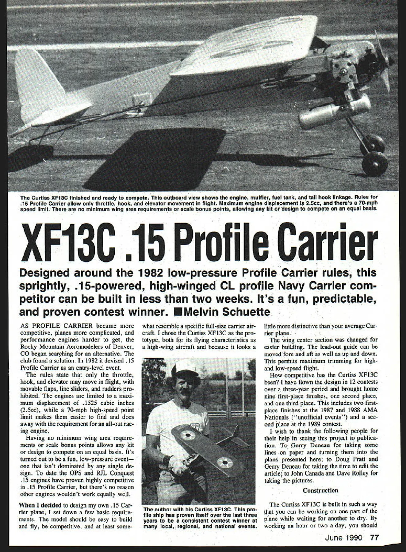
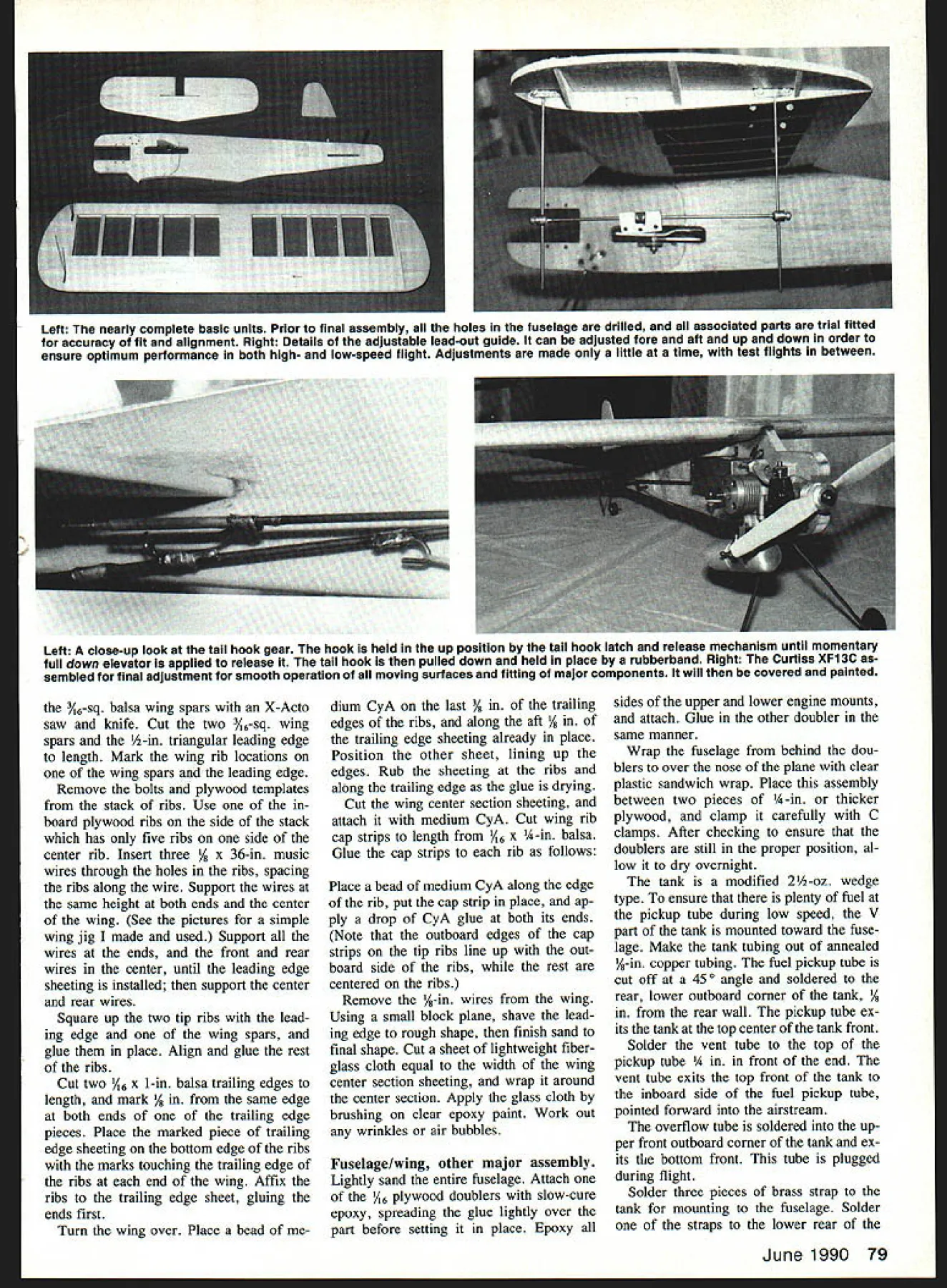
The Curtiss XF13C finished ready compete outboard view shows engine muffler fuel tank tail hook linkage Ruia 15 Profile Carrier allow throttie hook elevator movement flight Maximum engine displacement i 25cc theres 70-mph speed limit no minimum wing area requirements scale bonus points ailowing kit design compete equal basis XF13C 15 Profile Carrier Designed around 1982 low-pressure Profile Carrier rules sprightly 15-powered high-winged CL profile Navy Carrier com petitor can built less two weeks Its fun predictable proven contest winner U Melvin Schuette AS PROFILE CARRIER became competitive planes complicated performance engines harder get Rocky Mountain Aeromodelers Denver CO began searching alternative club found solution 1982 devised 15 Profile Carrier entry-level event rules state throttle hook elevator may move flight movable flaps line sliders rudders pro hibited engines limited maxi mum displacement 1525 cubic inches 25cc 70-mph high-speed point limit makes easier find does away requirement all-out rac ing engine Having no minimum wing area require ments scale bonus points allows kit design compete equal basis Its turned out fun low-pressure event isnt dominated single de sign date OPS RJL Conquest 15 engines have proven highly competitive 15 Profile Carrier theres no reason other engines wouldnt work equally well decided design own 15 Car rier plane set down few basic require ments model should easy build fly competitive least somewhat resemble specific full-size carrier air craft chose Curtiss XFl3C pro totype both its flying characteristics high-wing aircraft because looks little distinctive average Car rier plane wing center section changed easier building lead-out guide can moved fore aft well up down permits maximum trimmiig highand low-speed flight competitive has Curtiss XFl3C have flown design 12 contests over three-year period brought home nine first-place finishes second place third place includes two firstplace finishes 1987 1988 AMA Nationals unofficial events sec ond place 1989 contest wish thank following people help seeing project publica tion Gerry Deneau taking some lines paper turning plans presented Doug Pratt Gerry Deneau taking time edit article John Canada Dave Rolley taking pictures Construction Curtiss XFl3C built such way can working part plane waiting another dry working hour two day should June 1990 77 author Curtiss XF13C pro file ship has proven itseif over last three years consistent contest winner local regional national events have airplane ready fly less two weeks Materials x 36-in medium balsa sheet % x 3 x 36-in hard balsa sheet /i6 x 3 x 35-in medium balsa sheet Five V16 x 3 x 36-in 4-6-lb balsa sheet 6 x 6 x 12-in 3-ply birch plywood Y32 x 2 x 2 -in 3-ply birch plywood % x 3/ x 12-in hard maple engine mounts i/6 x 36-in music wire /32 x 36-in music wire /i6 x 36-in music wire 020 x 36-in music wire 032 x 36-in music wire 078 x 36-in music wire 2-56 threaded rod quick link 4-40 threaded rod quick link pair 1 4n slim-line wheels 3A-in tail wheel 2-oz Carolina-Taffinder fuel tank -in copper tube i4 x 12-in brass strap medium control horn Two metal landing gear straps LRP short-span C27 belicrank pack lead-out cable pack Du-Bro EZ servo connectors A6-in wheel collar 2 oz lead tip weight Four %-in nylon landing gear straps x 1 x u-in aluminum nylon Five 4-40 x 1-in bolts locknuts Two 4-40 x -in bolts locknuts % x 36-in wood dowel Lightweight fiberglass cloth Clear epoxy paint hardener Paint Covering materials Fuselage Cut profile out %-in dium balsa engine mounts out % x %-in hardwood doublers out 6 plywood Insert engine mounts fuselage glue place Trial fit engine fuselage en gine mounts make corrections needed Lay plywood doublers place trace its rear edge onto fuse lage Remove doubler engine mounts sand fuselage Round edges bottom behind doubler top behind wing Cut two pieces lightweight fiberglass cloth reinforcement will cover area just under doublers behind wing overlapping bottom fuselage top behind wing Us ing brush attach glass cloth fu selage clear epoxy paint thin paint Use brush work out wrinides air bubbles allow cure overnight using epoxy paints sure work well-ventilated area Wing Use 4-6-lb A6 balsa unless other wise stated balsa-to-ply gluing done medium CyA cyanoacrylate glue balsa-to-balsa gluing thin CyA glue Cut three ribs out %2 plywood will used inboard tip rib other two templates stack cut sand rest ribs Stack together drill three %-in holes rib centerline 34 2/4 5A leading edge plywood ribs holes used simple homemade wing jig shown pictures Hold three plywood ribs together 4-40 bolts nuts using -in holes ribs Sand leading edge edge three ribs same shape Un bolt ribs turn ribs over sandwich between other two re bolt assembly Sand edges same size previously sanded edges will ensure identical upper lower wing airfoil shapes Cut 11 pieces A6 balsa slightly larger piece -in balsa Cut out plywood rib templates Stack five pieces V16 balsa side -in balsa piece remaining six pieces other side Using plywood rib templates guide drill three -in holes through stack balsa ribs Sandwich ribs between two plywood rib tem plates fasten together 4-40 bolts nuts utilizing holes ribs rib templates Using small block razor plane shave top bottom edges balsa ribs al down plywood templates Sand sides ribs down templates Cut out notches balsa ribs 78 Model Aviation Brett Smith Gilbert IA releases authors Curtiss XF1 3C contest Omaha NE winning flight Omaha contest Note arresting gear carrier deck Navy Carrier event combination both high- low-speed flights along arrested landing Curtiss XF1 3C ing flown nose-high picture during low-speed clocking segment flight Left Its much easier build model kitting first Choosing wood easier construction goes much smoothly swiftly maior components building Curtiss XF13C have cut out displayed photo Above nearly com plete wing still its jig order ensure straight wing au thor constructed jig -in plywood music wire music wire left until wing sheeting cap strips glued place Details building jig included text Left The nearly complete basic units Prior final assembly holes fuselage drilled associated parts trial fitted accuracy fit alignment Right Details adjustable lead-out guide can adjusted fore aft up down order ensure optimum performance both high- low-speed flight Adjustments made little time test flights between Left A close-up look tail hook gear hook held up position tail hook latch release mechanism until momentary full down elevator applied release tall hook pulled down held place rubberband Right Curtiss XF13C sembled final adluatment smooth operation moving surfaces fitting major components will covered painted Y6-sq balsa wing spars X-Acto saw knife Cut two 346-sq wing spars -in triangular leading edge length Mark wing rib locations wing spars leading edge Remove bolts plywood templates stack ribs Use board plywood ribs side stack has five ribs side center rib Insert three / x 36-in music wires through holes ribs spacing ribs along wire Support wires same height both ends center wing See pictures simple wing jig made used Support wires ends front rear wires center until leading edge sheeting installed support center rear wires Square up two tip ribs lead ing edge wing spars glue place Align glue rest ribs Cut two A6 x 1-in balsa trailing edges length mark edge both ends trailing edge pieces Place marked piece trailing edge sheeting bottom edge ribs marks touching trailing edge ribs end wing Affix ribs trailing edge sheet gluing ends first Turn wing over Place bead medium CyA last ling edges ribs along aft trailing edge sheeting already place Position other sheet lining up edges Rub sheeting ribs along trailing edge glue drying Cut wing center section sheeting attach medium CyA Cut wing rib cap strips length /16 x A-in balsa Glue cap strips rib follows Place bead medium CyA along edge rib put cap strip place ap ply drop CyA glue both its ends Note outboard edges cap strips tip ribs line up out board side ribs rest centered ribs Remove -in wires wing Using small block plane shave lead ing edge rough shape finish sand final shape Cut sheet lightweight fiber glass cloth equal width wing center section sheeting wrap around center section Apply glass cloth brushing clear epoxy paint Work out wrinkles air bubbles Fuselagelwiag other major assembly Lightly sand entire fuselage Attach /16 plywood doublers slow-cure epoxy spreading glue lightly over part before setting place Epoxy sides upper lower engine mounts attach Glue other doubler same manner Wrap fuselage behind dou blers over nose plane clear plastic sandwich wrap Place assembly between two pieces A-in thicker plywood clamp carefully C clamps After checking ensure doublers still proper position al low dry overnight tank modified 2-oz wedge type ensure plenty fuel pickup tube during low speed V part tank mounted toward fuse lage Make tank tubing out annealed -in copper tubing fuel pickup tube cut off 450 angle soldered rear lower outboard corner tank / rear wall pickup tube ex its tank top center tank front Solder vent tube top pickup tube in front end vent tube exits top front tank inboard side fuel pickup tube pointed forward airstream overflow tube soldered up per front outboard corner tank ex its bottom front tube plugged during flight Solder three pieces brass strap tank mounting fuselage Solder straps lower rear June 1990 79 tank certain upper rear mount plywood doubler Drill straps small screws used mount tank fuselage Bend main landing gear tail wheel gear tail hook %-in 078-in /32 music wire respectively Mark cut out slot belicrank mount fuselage Cut out tail hook doublers Drill two %2 holes doubler center tail hook 440 hook stop bolt Glue doublers place using medium CyA drill two 3A2 holes through fuselage insert tail hook through doubler fuse lage Place other tail hook doubler over tail hook align stop bolt hole glue place medium CyA Mark drill mounting holes en gine fuel tank main landing gear land ing gear straps landing gear straps held place 4-40 bolts locknuts Mark drill hole fuselage tail wheel gear Mark fuselage tail wheel landing gear wire rest against cut groove marked wire will fit flush Coat tail wheel wire area contacts fu selage gap-filling CyA glue wire fuselage Cut two pieces lightweight fiberglass reinforce tail wheel wire mounting making piece /2 wider 14 longer other Using brush coat smaller piece either clear epoxy paint finishing resin first layer place apply second same manner Use slow-cure epoxy glue bellcrank mount place epoxy has cured drill two A-in holes through bot tom fuselage lower engine mount bellcrank mount Cut /8-in dowels length cover either white glue slow-cure epoxy insert holes Make sure dowels flush top belicrank mount bot tom fuselage Glue wing fuselage slowcure epoxy aligning fuselage follows Looking down model place square draftsmans triangle along fu selage trailing edge wing Se cure wing inserting pins through center fuselage leading trailing edges Align wing tilt putting pins wing tip bottom fuse lage just front spar Lay square spar up against side fu selage Holding wing position wrap string fine wire around pins wing tip wrap pin bottom fuselage finally other wing tip pin Set wing aside dry Elevator stabilizer Cut parts 3A6 medium balsa mark slot hinges Cut elevator joiner /32 music wire Mark location holes elevator halves wire joiner carefully drill holes leading edge elevator half notched joiner wire fits flush against elevator Round leading edge el evator half will give 350 450 up down elevator travel Insert wire joiner half elevator Insert hinges elevator sliding respective slots stabilizer position elevator Align hinges elevators move freely Drill A6 hole through stabilizer el evator center hinge pin point Insert wire joiner through slot fuselage stabilizer set stabilizer place Move wire joiner up down check free travel friction remove stabilizer joiner enlarge rear slot Reinstall joiner stabilizer ensure sta bilizer square fuselage glue place Insert toothpick pins through hinges stabilizer elevators se curing thin CyA applied both sides stabilizer elevators Cut sand toothpicks flush stab/ele vator surface Cut out rudder A-in hard balsa sand bottom edge round Glue place medium CyA Glue two ounces tip weight top side outboard wing tip using slowcure epoxy Finishing Due higher nitro content fuel used carrier airplanes prefer use epoxy paint throughout thats final word finishing Select other method wish patterned model after scheme used prototype airplane painted aluminum yellow up per half wing stabilizer eleva tors liberal 15 Profile Carrier rules allow choose paint scheme desired Cover wing favorite ironon material Tape off edges cover ing joins balsa painted leaving 4 exposed Use paper tape mask rest wing seal wood surfaces painting apply two coats K&B clear paint satin hardener sanding between coats Spray coat K&B primer allow dry overnight sand until little re mains Spray second coat primer sand lightly after drying Spray aluminum color coat allow dry youre adopting scheme used pro totype mask tape off top half stabilizer elevators rest fuselage paint yellow Tape off outline canopy paint contrasting color paint thoroughly dry remove tape pa per model Final details lead-out guide made either /6 aluminum nylon other materials can used Drill holes lead-out guide before cutting out notch wheel collar will go lead-out guide cross brace made TOP AND BOTTOM I/0 BALSA SHEET WINO TIP N _____ 1v IWHTEII BES LEADOSTL B6ISA 1/1615 I/A BALSA CAP STRIPS IIfS SIB SOLES 5f35povs cEBELLCRANK SUPPORT 3/3U PLYWOOD OUR SO VERTICAL LEADOUT GUIDE RUO WING FUEL TANK STABILIZER 15 ENGINE THROTTLE EIITENSON 5/00 BRASS TUBING FLATTEN AS NEEDES I-I/O OIA BACINA WHEELS FRONT VIE /16 music wire two Du-Bro EZ servo connectors Remove pin servo connector drill A6 hole pin located Cut piece A6 music wire fits snugly between leadout guide braces Slide servo connectors over lead-out guide brace solder cross brace servo connec tors Stay Brite silver solder Slide lead-out guide /16 wheel collar over cross brace put cross brace other servo connector silver solder place lead-outs can made either lead-out material 018-in stranded flying wire Bush lead-outs bellcrank piece annealed A6 x /2-in brass tubing slip through tubing allow ing enough protrude can wrapped Bend tubing center 900 angle slip through hole bellcrank Continue bending until tub80 Model Aviation Full-Size Plans Available Page 204 021/4 BALSA ECADINO EDGE 1~il1XL -4Vzuil ih li__ Ii / NG V PLAN 7[I -t I -4-tIAIAAIi ~I- K------- A I/16 BALSA SHEET TOP AND BOTTOM -4/IA WHEEL 004GB SOLDER ISS BRACE I/IA 010 MUSIC WIRE B CUT OFF FOB CROSS WIRE i-i -0-332 RIB PATTERN DOZ WNBII4 -TPWEORT 2\KI 4U B BA BEET WHOP I/IA BALSA SHEET RIM I/O BALSA SHEET RIM S/SD PLYWOOD RIB H 0 - 0 I/B BALSA SHEET TIP GOSSETS TOP ONLYMBASS STRAPS-SOLDERED TO FUEL TANK SENT TOME -- CAROLINATAFTFINDER 0-I/O 07 MEDIAN WEDGE FUEL TANK -I/B DIG COPPER TUBED SOLDER IN PLACEI FUEL SOPPLY TUBEOSERPLUW TOME D LEADOUT GUIDE BLOCK 3/IA NYLON OR ALOMINUM I FUEL TANK 15 ENGINE BRASS TUBE L-R SHORT S/AN C27SODERED IA THREADED -3 JNE BELCRANK -~ TO NW /USHROD- JEL TANK ET RETOL2-56 QUICK TTPICAL HINGE LOCATION 3/IA BALSA I SHEET ELERATOB ONTROL STAB. S/SO DIG MUSIC WIRE ELE JOINER S/IA MALBA SHEET STAMILZER AND ELEGATOR-S/IA t~iBALSA SHEET ER ELEV 093 THREGUED ROD WITH 4-HO QUICK LINKELESATOR CONTROL HORN -ORDER ELEG SO SE B 5/52 DIA MOSIC WIRE MOOR OLUER /KIII WASHERSH-HO MACHINE SCREW SCREW HIS WOOD BI SECURE WITH COG GLUE STABILIZERELESATOR A-AS MAChINE SCREW WITH A-AS BLIND NUT I-I/U RACING WREELS WASRERS - FUSELAGE VIEW EADOUT IHES JET H AS MACRINE SCREWS WITH H HO ML ND NUTS LY ERB SIC lAKE I/IA PLO DOUBLERS U S/R SHEET METAL S/A 02 FIBERGLASS MOTH SIDES SCREWS AYEH MOTH SIDES 000 MUSIC RUBBERWIRE ____________BAND 3/4 BIA TAILWHEEL 5/52 010 MUSIC WIRE WASHERS-SOLDERED S/H DIGTA LWHEEL TAILWHEEL IL I/B BALSA SHEET FIN / RUDDER SPECIFICATIONS WING SHAH NO AREA ENS INC S/A DIG TAILWREEL SOLDER WASHERS/H GALSA GREET2 LASERS MODEL AVIATION TO PUSHRODPROFILE FUSELAGEI 077/H 1AM 55 IN FUSELAGE SIDE VIEW RACINO WHEELSI/B 010 MUSIC WIRE LANDING SEAR I0545A CURTISS XF 13 C 15 CARRIER DESIGNED BY MELVIN SCHUTTE TRACING BY JOE DEMARCO IALL RIGHTS DRDNMfl ing just barely clears top bottom belicrank checking ensure will rotate holes Repeat other lead-outs Double wrap lead-outs fine copper wire bellcrank Mount bellcrank 4-40 screws blind nuts Install control horn outboard half elevator elevator pushrod made %2 music wire 4-40 threaded rod Put 90B bend music wire slide hole bellcrank end facing down Bend 4-40 threaded rod shape shown plans cut length Install 4-40 threaded quick link rod centering threaded portion Hold music wire bellcrank centered threaded rod elevator neutral Mark cut music wire meets end threaded rod Cut l-in-long piece -in brass copper tubing Slip over music wire threaded rod wire ends meet middle tub ing solder both ends tubing music wire threaded rod Thread lead-outs through lead-out guide wrap up down lines en suring theyre long enough full up down control both high low throt tle throttle lead-out will three inches longer other two use belicrank other listed plans youll have make sure length throttle line correct length checked up down lines equal throttle line pulled way out Its best have throttle linkage hooked up carburetor measur ing lead-outs Wrap end throt tle line Solder washer tail hook bend fits fuselage Put hook place dont solder other washer done until attach ments hook have soldered place Bend hook release latch hooks rubberbands 020 music wire small loop bent wrapped copper wire soldered hook make latch Make release short enough wont interfere up movement elevator yet long enough release hook almost full down el evator tail hook pulled held down rubberbands attached two 020 music wire hooks hooks attached tail hook other bottom side fuselage forward tail hook hook attached tail hook bent shape wrapped copper wire before being soldered onto tail hook Solder onto wire about inch 90 B bend fuselage hook Continued page 197 June 1990 81 ply dope will fill faster less overall weight Flying Allow finish cure week before checking warps remov ing may have developed Make sure wing properly aligned Test glide model adjusting incidence necessary until nice floating glide achieved Double-check CG location major cor rections incidence required Locating CG 76% fuel works out well model stabi lizer size prevents Astrostar go ing over top will tail-heavy model prevents excessive looping some times seen nose-heavy aircraft An tutely chosen CG location can effec tive means fine tuning power glide phases flight cant ac complished incidence corrections alone Dont afraid put Lite Ply spacer behind engine add tail weight necessary move CG its correct po sition Use pacifier pressure fuel tank con sistent engine run set timer 253 seconds model should climb steeply slight right turn Correct adverse turn tendencies rudder tabtrailing edge stock glued rear rudder Slowly lengthen engine run until full limit reached Properly trimmed model will make couple turns 12 sec onds smooth transition floating glide Once model properly trimmed ready contest flying would recom mend making first three four flights early day possible air nice thick Pay attention rest models thermal activity looks promising enough begin flyoff flights Picking good air acquired skill watching other fliers seem win lot can speed up learning process can flying versatile de pendable stable Free Flight model Im sure A-B Astrostar will bring much pleasure has given Product Sources Bradley Model Products 1337 Pine Sap Ct Orlando FL 32825 Jacks Models 7178 Aumsville Hwy Sa lem OR 97301 Kustom Kraftsmanship Box 3010 Fallbrook CA 92028 MRL 25108 Marguerite Pkwy B-160 Mission Viejo CA 92692 Curtiss XF1 3C/Schuette Continued page 81 bottom fuselage rubberbands positioned forward tail hook tension rubberband hook down Use small rubberbands Insert tail hook through doublers -S EEmmmmmmmmm SIG GLOW FUEL MANUFACTURED WITH THE PUREST FINEST QUALITY INGREDIENTS AVAILABLE * Superior Igniters Improve starting idle acceleration Youll notice power bargain fuels * Special Detergents Promote clean burning prevent residue buildup * Rust Inhibitors Protect engines corrosion After run oil needed engines * Film Strength Additives Increase lubricity provide extra lean run protection * Anti-Wear Additives Help keep engines running peak performance longer * Satisfaction Guaranteed FREE SHIPPING ON ORDERS OVER $1500 SIG CHAMPION 2-STROKE FUEL PINTUART GALLON 35% Nitro9 5$2595 SIG PREMIUM 4-STROKE FUEL 10% Nitromothane$1325 15% Nitromethano$1525 THE CHOICE OF CHAMPION FLYERS over 20 years SIG has blending finest quality model engine fuel available using finest quality ingredients instance Methanol use 995% pure very best grade money can buy also use real 100% pure Nitromethane get full measure youve paid based honest percentage-of-volume method percentage weight SIG fuels con tain 50-50 blend Bakers purest AA Castor Oil new improved Klotz Techniplate Synthetic Racing Oil maximum engine lubrication protection Based experience sincerely believe finest quality fuel can made price dont take word try some judge yourselftonces noblect change withoot notice See dealer first available order direct Call 800-247-5008 toll free orders Latest Catalog $300 SIG MANUFACTURING CO Montezuma IA 50171 solder washer opposite side fuselage Apply drop medium CyA tail hook doubler stop-holes doublers harden Screw 4-40 bolt through holes screw enters tail hook side passes through fuselage ends flush outside edge dou bler other side Use #2 x 3A-in screws mount fuel tank fuselage Mount main landing gear lock place A-in nylon landing gear straps 4-40 bolts nuts Use Glenn Lee 1 /2-in-dia racing wheels similar type Solder inside washer onto landing gear axle slip wheel Put small piece sandpaper litI I I I I I I U U U I I U U I I U tle larger washers used over landing gear wire solder outside washer onto wire Remove sandpa per between washer wheel Re peat other wheel help smooth out throttle response during low-speed flight throttle arm lengthened full movement bellcrank required fully open close carburetor Remove throttle arm carburetor Cut 34 -in-long piece Y32 brass tubing flatten fit over throttle arm Sand file off anodizing throttle arm extension will soldered Place flattened tubing over throttle arm continue flattening un til its tight against throttle arm Solder throttle arm extension place June 1990 197 U U U U I I I U U I I I U U U I I U U Bill Effinger * says Plan Pattern0 Sees gixe esovyned designs yes want have selected best c/exalt desigxs time cheese pamenns part important exclusive feature One-Third Scale Piper Tn-Pacer PA-22 118-3/8 wing span sq mong area 20 30 cid engines Fot 45 channel RIO ox 12 lbs 16 overall length Plywoodlbalsa tulseluge removeablo wing yanels steerable nose wheel designed exty ground hondling aed aothentrc stain flight yorlormancv RC2S 3I $2996 1/3 Scale Piper Cub J-3 119 wing spun ongth o 2800 sc wing arco 4 oh RIC 20-30 cid engines RC3S-2 5 Quarter Scale- WWI SE-BA 88th wiog span sq wing aree 78 22 engines ACOS- 6 FOKKER DR-i TRIPLANE 72 wing span sq wing area 78 tolSO engines RCOS8 6 SOPWITH CAMEL P1 84 wing span 0 sq wing area11 lbs mix AIC wood haixa weettoctixe over 68 sq ft drawings 6C05-1 1 6 Quaaler Scale WWI Fokker New V 11 88 wingspan sq wing area 8825 cid engine cheflIbs RCOS-h 82495 Full cantilever wings leo flying wiresl Removal engine unit Shock mounted landing gear Balnalplywoud fuselage built-up hiusa wing 6111 Effieger Paxertleg Meerber AMA NPFS Hall Penner yrivw art fur onmyloro plans sue uxuamhlv b dorailed pane lines PLEASE ADO 8288 for shippleg mailing tubal Sew 1888 Plan sets bruvytro returdablo yr first urderil SPAD C-XIII 57g/rVtingnpa 22esq wingerea13 03 engexe IneghtahenOcapes IRCOS-8 6 TECHNICAL SERVICES URn 1 Box 2900 Santa Rosa Beech PL324B9 TOWERSTWWI Special StockSuggestedSPECIAL NumberRetailPRICE HEOlOC 1/8X6rx121560/6pCs1299/Opca HEOllO 1/8x12x244950/6 pcs349916pcs HE0120 1/8rx1 Zx484650/3 pea3299/3 pcs drill V6 hole end length extension may vary carburetor used Mount engine 4-40 bolts locknuts Insert washer between bolt heads engine mounting lugs other between doubler locknuts throttle linkage made 2-56 threaded rod Bend rod shape stall threaded quick link cen tered threaded portion rod tach linkage carburetor throttle arm Install solder quick link throt tle arm bellcrank Ensure bellcrank carburetor high-speed position- use bellcrank shown plans pull way out up down lead-outs Position threaded rod against solder link cut length should protrude about A6 Solder threaded rod quick link Using lead-outs work throttle link age ensure free throttle movement Work elevator ensure moves freely both high low speeds well mid range Flying Start lead-out guide 2 bottom wing 1 front lead-out guide brace Trim plane high speed moving leadout guide forward back until plane flies close 70 mph can get 257 seconds eight laps Trim plane low speed moving lead-out guide either forward back either up down Make adjustments lead-out guide time moving guide just little time Fly plane before making further adjustments No matter workmanlike build ing nothing can take place practice learning handle particular model Fly aircraft kinds weather youll ready anything contest day have questions about building flying Curtiss XF13C feel free contact PO Box 240 Auburn KS 66402 through CompuServes ModelNet addressed 731702741 responding advertisers mention read about Model Aviation WRAM Show/Myers Continued page 92 mounts lists $7995 Look inside wings new Sailplanes Ace RC Inc r just down hail showing prototype its AM-PWM Micropro 8000 sys tem offered either $175 update companys Silver Seven AM transmitter complete new transmitter metal-gimbal sticks $375 will available spring 1990 Since can update existing Silver Seven system Micropro offers low-cost troduction computer-assisted aircraft character istics fact R5232 port available op tion port allows exchange aircraft con trol parameters IBM-compatible com puter option includes MS-DOS applica tion program configures mixing etc can learn little bit about things Sometime future another option will let play aircraft characteristics home via computer simulation Also available will transmitter box control sticks will plug computers game port Youll able maneuvers Dave Browns computer simulation allows plus try out wild ideas intend pump real RC model Like Airtronics Ace uses TOSEPROMr planned exchangeable updates Programming mixing control throws servo reversing etc configuration done via control sticks used like arrow keys computer keyboard search 198 Model Aviation SUPER FAST RECOVERY SYSTEMS Making Flight Failsafe e Superiority Rocket Fast Deployment e cost effective means insuring aircraft & its gear e Avoid fatal mishaps e Great novice expert LL2 has Recovery System Fit Aircraft SPECIFY ENGINE SIZE Plans Sand lg K/f Sand 199w Plus 25a Shipping & Handling PO BOX 629 ON WI 54016 0 TOWER HOBBIES has Mighty LItE worlds first premium BodseasytnyCA time right. use Mighty LiteM Coil toll free 1-800-637-6050 Refer toad#01066 After setting up booth Lowell Pierson Scande Research Inc takes quiet moment build another Helicopter Scande sells di rectly builders carries nice line hand-launched rubber-powered models
Edition: Model Aviation - 1990/06
Page Numbers: 77, 78, 79, 80, 81, 197, 198

Edition: Model Aviation - 1990/06
Page Numbers: 77, 78, 79, 80, 81, 197, 198
The Curtiss XF13C finished ready compete outboard view shows engine muffler fuel tank tail hook linkage Ruia 15 Profile Carrier allow throttie hook elevator movement flight Maximum engine displacement i 25cc theres 70-mph speed limit no minimum wing area requirements scale bonus points ailowing kit design compete equal basis XF13C 15 Profile Carrier Designed around 1982 low-pressure Profile Carrier rules sprightly 15-powered high-winged CL profile Navy Carrier com petitor can built less two weeks Its fun predictable proven contest winner U Melvin Schuette AS PROFILE CARRIER became competitive planes complicated performance engines harder get Rocky Mountain Aeromodelers Denver CO began searching alternative club found solution 1982 devised 15 Profile Carrier entry-level event rules state throttle hook elevator may move flight movable flaps line sliders rudders pro hibited engines limited maxi mum displacement 1525 cubic inches 25cc 70-mph high-speed point limit makes easier find does away requirement all-out rac ing engine Having no minimum wing area require ments scale bonus points allows kit design compete equal basis Its turned out fun low-pressure event isnt dominated single de sign date OPS RJL Conquest 15 engines have proven highly competitive 15 Profile Carrier theres no reason other engines wouldnt work equally well decided design own 15 Car rier plane set down few basic require ments model should easy build fly competitive least somewhat resemble specific full-size carrier air craft chose Curtiss XFl3C pro totype both its flying characteristics high-wing aircraft because looks little distinctive average Car rier plane wing center section changed easier building lead-out guide can moved fore aft well up down permits maximum trimmiig highand low-speed flight competitive has Curtiss XFl3C have flown design 12 contests over three-year period brought home nine first-place finishes second place third place includes two firstplace finishes 1987 1988 AMA Nationals unofficial events sec ond place 1989 contest wish thank following people help seeing project publica tion Gerry Deneau taking some lines paper turning plans presented Doug Pratt Gerry Deneau taking time edit article John Canada Dave Rolley taking pictures Construction Curtiss XFl3C built such way can working part plane waiting another dry working hour two day should June 1990 77 author Curtiss XF13C pro file ship has proven itseif over last three years consistent contest winner local regional national events have airplane ready fly less two weeks Materials x 36-in medium balsa sheet % x 3 x 36-in hard balsa sheet /i6 x 3 x 35-in medium balsa sheet Five V16 x 3 x 36-in 4-6-lb balsa sheet 6 x 6 x 12-in 3-ply birch plywood Y32 x 2 x 2 -in 3-ply birch plywood % x 3/ x 12-in hard maple engine mounts i/6 x 36-in music wire /32 x 36-in music wire /i6 x 36-in music wire 020 x 36-in music wire 032 x 36-in music wire 078 x 36-in music wire 2-56 threaded rod quick link 4-40 threaded rod quick link pair 1 4n slim-line wheels 3A-in tail wheel 2-oz Carolina-Taffinder fuel tank -in copper tube i4 x 12-in brass strap medium control horn Two metal landing gear straps LRP short-span C27 belicrank pack lead-out cable pack Du-Bro EZ servo connectors A6-in wheel collar 2 oz lead tip weight Four %-in nylon landing gear straps x 1 x u-in aluminum nylon Five 4-40 x 1-in bolts locknuts Two 4-40 x -in bolts locknuts % x 36-in wood dowel Lightweight fiberglass cloth Clear epoxy paint hardener Paint Covering materials Fuselage Cut profile out %-in dium balsa engine mounts out % x %-in hardwood doublers out 6 plywood Insert engine mounts fuselage glue place Trial fit engine fuselage en gine mounts make corrections needed Lay plywood doublers place trace its rear edge onto fuse lage Remove doubler engine mounts sand fuselage Round edges bottom behind doubler top behind wing Cut two pieces lightweight fiberglass cloth reinforcement will cover area just under doublers behind wing overlapping bottom fuselage top behind wing Us ing brush attach glass cloth fu selage clear epoxy paint thin paint Use brush work out wrinides air bubbles allow cure overnight using epoxy paints sure work well-ventilated area Wing Use 4-6-lb A6 balsa unless other wise stated balsa-to-ply gluing done medium CyA cyanoacrylate glue balsa-to-balsa gluing thin CyA glue Cut three ribs out %2 plywood will used inboard tip rib other two templates stack cut sand rest ribs Stack together drill three %-in holes rib centerline 34 2/4 5A leading edge plywood ribs holes used simple homemade wing jig shown pictures Hold three plywood ribs together 4-40 bolts nuts using -in holes ribs Sand leading edge edge three ribs same shape Un bolt ribs turn ribs over sandwich between other two re bolt assembly Sand edges same size previously sanded edges will ensure identical upper lower wing airfoil shapes Cut 11 pieces A6 balsa slightly larger piece -in balsa Cut out plywood rib templates Stack five pieces V16 balsa side -in balsa piece remaining six pieces other side Using plywood rib templates guide drill three -in holes through stack balsa ribs Sandwich ribs between two plywood rib tem plates fasten together 4-40 bolts nuts utilizing holes ribs rib templates Using small block razor plane shave top bottom edges balsa ribs al down plywood templates Sand sides ribs down templates Cut out notches balsa ribs 78 Model Aviation Brett Smith Gilbert IA releases authors Curtiss XF1 3C contest Omaha NE winning flight Omaha contest Note arresting gear carrier deck Navy Carrier event combination both high- low-speed flights along arrested landing Curtiss XF1 3C ing flown nose-high picture during low-speed clocking segment flight Left Its much easier build model kitting first Choosing wood easier construction goes much smoothly swiftly maior components building Curtiss XF13C have cut out displayed photo Above nearly com plete wing still its jig order ensure straight wing au thor constructed jig -in plywood music wire music wire left until wing sheeting cap strips glued place Details building jig included text Left The nearly complete basic units Prior final assembly holes fuselage drilled associated parts trial fitted accuracy fit alignment Right Details adjustable lead-out guide can adjusted fore aft up down order ensure optimum performance both high- low-speed flight Adjustments made little time test flights between Left A close-up look tail hook gear hook held up position tail hook latch release mechanism until momentary full down elevator applied release tall hook pulled down held place rubberband Right Curtiss XF13C sembled final adluatment smooth operation moving surfaces fitting major components will covered painted Y6-sq balsa wing spars X-Acto saw knife Cut two 346-sq wing spars -in triangular leading edge length Mark wing rib locations wing spars leading edge Remove bolts plywood templates stack ribs Use board plywood ribs side stack has five ribs side center rib Insert three / x 36-in music wires through holes ribs spacing ribs along wire Support wires same height both ends center wing See pictures simple wing jig made used Support wires ends front rear wires center until leading edge sheeting installed support center rear wires Square up two tip ribs lead ing edge wing spars glue place Align glue rest ribs Cut two A6 x 1-in balsa trailing edges length mark edge both ends trailing edge pieces Place marked piece trailing edge sheeting bottom edge ribs marks touching trailing edge ribs end wing Affix ribs trailing edge sheet gluing ends first Turn wing over Place bead medium CyA last ling edges ribs along aft trailing edge sheeting already place Position other sheet lining up edges Rub sheeting ribs along trailing edge glue drying Cut wing center section sheeting attach medium CyA Cut wing rib cap strips length /16 x A-in balsa Glue cap strips rib follows Place bead medium CyA along edge rib put cap strip place ap ply drop CyA glue both its ends Note outboard edges cap strips tip ribs line up out board side ribs rest centered ribs Remove -in wires wing Using small block plane shave lead ing edge rough shape finish sand final shape Cut sheet lightweight fiber glass cloth equal width wing center section sheeting wrap around center section Apply glass cloth brushing clear epoxy paint Work out wrinkles air bubbles Fuselagelwiag other major assembly Lightly sand entire fuselage Attach /16 plywood doublers slow-cure epoxy spreading glue lightly over part before setting place Epoxy sides upper lower engine mounts attach Glue other doubler same manner Wrap fuselage behind dou blers over nose plane clear plastic sandwich wrap Place assembly between two pieces A-in thicker plywood clamp carefully C clamps After checking ensure doublers still proper position al low dry overnight tank modified 2-oz wedge type ensure plenty fuel pickup tube during low speed V part tank mounted toward fuse lage Make tank tubing out annealed -in copper tubing fuel pickup tube cut off 450 angle soldered rear lower outboard corner tank / rear wall pickup tube ex its tank top center tank front Solder vent tube top pickup tube in front end vent tube exits top front tank inboard side fuel pickup tube pointed forward airstream overflow tube soldered up per front outboard corner tank ex its bottom front tube plugged during flight Solder three pieces brass strap tank mounting fuselage Solder straps lower rear June 1990 79 tank certain upper rear mount plywood doubler Drill straps small screws used mount tank fuselage Bend main landing gear tail wheel gear tail hook %-in 078-in /32 music wire respectively Mark cut out slot belicrank mount fuselage Cut out tail hook doublers Drill two %2 holes doubler center tail hook 440 hook stop bolt Glue doublers place using medium CyA drill two 3A2 holes through fuselage insert tail hook through doubler fuse lage Place other tail hook doubler over tail hook align stop bolt hole glue place medium CyA Mark drill mounting holes en gine fuel tank main landing gear land ing gear straps landing gear straps held place 4-40 bolts locknuts Mark drill hole fuselage tail wheel gear Mark fuselage tail wheel landing gear wire rest against cut groove marked wire will fit flush Coat tail wheel wire area contacts fu selage gap-filling CyA glue wire fuselage Cut two pieces lightweight fiberglass reinforce tail wheel wire mounting making piece /2 wider 14 longer other Using brush coat smaller piece either clear epoxy paint finishing resin first layer place apply second same manner Use slow-cure epoxy glue bellcrank mount place epoxy has cured drill two A-in holes through bot tom fuselage lower engine mount bellcrank mount Cut /8-in dowels length cover either white glue slow-cure epoxy insert holes Make sure dowels flush top belicrank mount bot tom fuselage Glue wing fuselage slowcure epoxy aligning fuselage follows Looking down model place square draftsmans triangle along fu selage trailing edge wing Se cure wing inserting pins through center fuselage leading trailing edges Align wing tilt putting pins wing tip bottom fuse lage just front spar Lay square spar up against side fu selage Holding wing position wrap string fine wire around pins wing tip wrap pin bottom fuselage finally other wing tip pin Set wing aside dry Elevator stabilizer Cut parts 3A6 medium balsa mark slot hinges Cut elevator joiner /32 music wire Mark location holes elevator halves wire joiner carefully drill holes leading edge elevator half notched joiner wire fits flush against elevator Round leading edge el evator half will give 350 450 up down elevator travel Insert wire joiner half elevator Insert hinges elevator sliding respective slots stabilizer position elevator Align hinges elevators move freely Drill A6 hole through stabilizer el evator center hinge pin point Insert wire joiner through slot fuselage stabilizer set stabilizer place Move wire joiner up down check free travel friction remove stabilizer joiner enlarge rear slot Reinstall joiner stabilizer ensure sta bilizer square fuselage glue place Insert toothpick pins through hinges stabilizer elevators se curing thin CyA applied both sides stabilizer elevators Cut sand toothpicks flush stab/ele vator surface Cut out rudder A-in hard balsa sand bottom edge round Glue place medium CyA Glue two ounces tip weight top side outboard wing tip using slowcure epoxy Finishing Due higher nitro content fuel used carrier airplanes prefer use epoxy paint throughout thats final word finishing Select other method wish patterned model after scheme used prototype airplane painted aluminum yellow up per half wing stabilizer eleva tors liberal 15 Profile Carrier rules allow choose paint scheme desired Cover wing favorite ironon material Tape off edges cover ing joins balsa painted leaving 4 exposed Use paper tape mask rest wing seal wood surfaces painting apply two coats K&B clear paint satin hardener sanding between coats Spray coat K&B primer allow dry overnight sand until little re mains Spray second coat primer sand lightly after drying Spray aluminum color coat allow dry youre adopting scheme used pro totype mask tape off top half stabilizer elevators rest fuselage paint yellow Tape off outline canopy paint contrasting color paint thoroughly dry remove tape pa per model Final details lead-out guide made either /6 aluminum nylon other materials can used Drill holes lead-out guide before cutting out notch wheel collar will go lead-out guide cross brace made TOP AND BOTTOM I/0 BALSA SHEET WINO TIP N _____ 1v IWHTEII BES LEADOSTL B6ISA 1/1615 I/A BALSA CAP STRIPS IIfS SIB SOLES 5f35povs cEBELLCRANK SUPPORT 3/3U PLYWOOD OUR SO VERTICAL LEADOUT GUIDE RUO WING FUEL TANK STABILIZER 15 ENGINE THROTTLE EIITENSON 5/00 BRASS TUBING FLATTEN AS NEEDES I-I/O OIA BACINA WHEELS FRONT VIE /16 music wire two Du-Bro EZ servo connectors Remove pin servo connector drill A6 hole pin located Cut piece A6 music wire fits snugly between leadout guide braces Slide servo connectors over lead-out guide brace solder cross brace servo connec tors Stay Brite silver solder Slide lead-out guide /16 wheel collar over cross brace put cross brace other servo connector silver solder place lead-outs can made either lead-out material 018-in stranded flying wire Bush lead-outs bellcrank piece annealed A6 x /2-in brass tubing slip through tubing allow ing enough protrude can wrapped Bend tubing center 900 angle slip through hole bellcrank Continue bending until tub80 Model Aviation Full-Size Plans Available Page 204 021/4 BALSA ECADINO EDGE 1~il1XL -4Vzuil ih li__ Ii / NG V PLAN 7[I -t I -4-tIAIAAIi ~I- K------- A I/16 BALSA SHEET TOP AND BOTTOM -4/IA WHEEL 004GB SOLDER ISS BRACE I/IA 010 MUSIC WIRE B CUT OFF FOB CROSS WIRE i-i -0-332 RIB PATTERN DOZ WNBII4 -TPWEORT 2\KI 4U B BA BEET WHOP I/IA BALSA SHEET RIM I/O BALSA SHEET RIM S/SD PLYWOOD RIB H 0 - 0 I/B BALSA SHEET TIP GOSSETS TOP ONLYMBASS STRAPS-SOLDERED TO FUEL TANK SENT TOME -- CAROLINATAFTFINDER 0-I/O 07 MEDIAN WEDGE FUEL TANK -I/B DIG COPPER TUBED SOLDER IN PLACEI FUEL SOPPLY TUBEOSERPLUW TOME D LEADOUT GUIDE BLOCK 3/IA NYLON OR ALOMINUM I FUEL TANK 15 ENGINE BRASS TUBE L-R SHORT S/AN C27SODERED IA THREADED -3 JNE BELCRANK -~ TO NW /USHROD- JEL TANK ET RETOL2-56 QUICK TTPICAL HINGE LOCATION 3/IA BALSA I SHEET ELERATOB ONTROL STAB. S/SO DIG MUSIC WIRE ELE JOINER S/IA MALBA SHEET STAMILZER AND ELEGATOR-S/IA t~iBALSA SHEET ER ELEV 093 THREGUED ROD WITH 4-HO QUICK LINKELESATOR CONTROL HORN -ORDER ELEG SO SE B 5/52 DIA MOSIC WIRE MOOR OLUER /KIII WASHERSH-HO MACHINE SCREW SCREW HIS WOOD BI SECURE WITH COG GLUE STABILIZERELESATOR A-AS MAChINE SCREW WITH A-AS BLIND NUT I-I/U RACING WREELS WASRERS - FUSELAGE VIEW EADOUT IHES JET H AS MACRINE SCREWS WITH H HO ML ND NUTS LY ERB SIC lAKE I/IA PLO DOUBLERS U S/R SHEET METAL S/A 02 FIBERGLASS MOTH SIDES SCREWS AYEH MOTH SIDES 000 MUSIC RUBBERWIRE ____________BAND 3/4 BIA TAILWHEEL 5/52 010 MUSIC WIRE WASHERS-SOLDERED S/H DIGTA LWHEEL TAILWHEEL IL I/B BALSA SHEET FIN / RUDDER SPECIFICATIONS WING SHAH NO AREA ENS INC S/A DIG TAILWREEL SOLDER WASHERS/H GALSA GREET2 LASERS MODEL AVIATION TO PUSHRODPROFILE FUSELAGEI 077/H 1AM 55 IN FUSELAGE SIDE VIEW RACINO WHEELSI/B 010 MUSIC WIRE LANDING SEAR I0545A CURTISS XF 13 C 15 CARRIER DESIGNED BY MELVIN SCHUTTE TRACING BY JOE DEMARCO IALL RIGHTS DRDNMfl ing just barely clears top bottom belicrank checking ensure will rotate holes Repeat other lead-outs Double wrap lead-outs fine copper wire bellcrank Mount bellcrank 4-40 screws blind nuts Install control horn outboard half elevator elevator pushrod made %2 music wire 4-40 threaded rod Put 90B bend music wire slide hole bellcrank end facing down Bend 4-40 threaded rod shape shown plans cut length Install 4-40 threaded quick link rod centering threaded portion Hold music wire bellcrank centered threaded rod elevator neutral Mark cut music wire meets end threaded rod Cut l-in-long piece -in brass copper tubing Slip over music wire threaded rod wire ends meet middle tub ing solder both ends tubing music wire threaded rod Thread lead-outs through lead-out guide wrap up down lines en suring theyre long enough full up down control both high low throt tle throttle lead-out will three inches longer other two use belicrank other listed plans youll have make sure length throttle line correct length checked up down lines equal throttle line pulled way out Its best have throttle linkage hooked up carburetor measur ing lead-outs Wrap end throt tle line Solder washer tail hook bend fits fuselage Put hook place dont solder other washer done until attach ments hook have soldered place Bend hook release latch hooks rubberbands 020 music wire small loop bent wrapped copper wire soldered hook make latch Make release short enough wont interfere up movement elevator yet long enough release hook almost full down el evator tail hook pulled held down rubberbands attached two 020 music wire hooks hooks attached tail hook other bottom side fuselage forward tail hook hook attached tail hook bent shape wrapped copper wire before being soldered onto tail hook Solder onto wire about inch 90 B bend fuselage hook Continued page 197 June 1990 81 ply dope will fill faster less overall weight Flying Allow finish cure week before checking warps remov ing may have developed Make sure wing properly aligned Test glide model adjusting incidence necessary until nice floating glide achieved Double-check CG location major cor rections incidence required Locating CG 76% fuel works out well model stabi lizer size prevents Astrostar go ing over top will tail-heavy model prevents excessive looping some times seen nose-heavy aircraft An tutely chosen CG location can effec tive means fine tuning power glide phases flight cant ac complished incidence corrections alone Dont afraid put Lite Ply spacer behind engine add tail weight necessary move CG its correct po sition Use pacifier pressure fuel tank con sistent engine run set timer 253 seconds model should climb steeply slight right turn Correct adverse turn tendencies rudder tabtrailing edge stock glued rear rudder Slowly lengthen engine run until full limit reached Properly trimmed model will make couple turns 12 sec onds smooth transition floating glide Once model properly trimmed ready contest flying would recom mend making first three four flights early day possible air nice thick Pay attention rest models thermal activity looks promising enough begin flyoff flights Picking good air acquired skill watching other fliers seem win lot can speed up learning process can flying versatile de pendable stable Free Flight model Im sure A-B Astrostar will bring much pleasure has given Product Sources Bradley Model Products 1337 Pine Sap Ct Orlando FL 32825 Jacks Models 7178 Aumsville Hwy Sa lem OR 97301 Kustom Kraftsmanship Box 3010 Fallbrook CA 92028 MRL 25108 Marguerite Pkwy B-160 Mission Viejo CA 92692 Curtiss XF1 3C/Schuette Continued page 81 bottom fuselage rubberbands positioned forward tail hook tension rubberband hook down Use small rubberbands Insert tail hook through doublers -S EEmmmmmmmmm SIG GLOW FUEL MANUFACTURED WITH THE PUREST FINEST QUALITY INGREDIENTS AVAILABLE * Superior Igniters Improve starting idle acceleration Youll notice power bargain fuels * Special Detergents Promote clean burning prevent residue buildup * Rust Inhibitors Protect engines corrosion After run oil needed engines * Film Strength Additives Increase lubricity provide extra lean run protection * Anti-Wear Additives Help keep engines running peak performance longer * Satisfaction Guaranteed FREE SHIPPING ON ORDERS OVER $1500 SIG CHAMPION 2-STROKE FUEL PINTUART GALLON 35% Nitro9 5$2595 SIG PREMIUM 4-STROKE FUEL 10% Nitromothane$1325 15% Nitromethano$1525 THE CHOICE OF CHAMPION FLYERS over 20 years SIG has blending finest quality model engine fuel available using finest quality ingredients instance Methanol use 995% pure very best grade money can buy also use real 100% pure Nitromethane get full measure youve paid based honest percentage-of-volume method percentage weight SIG fuels con tain 50-50 blend Bakers purest AA Castor Oil new improved Klotz Techniplate Synthetic Racing Oil maximum engine lubrication protection Based experience sincerely believe finest quality fuel can made price dont take word try some judge yourselftonces noblect change withoot notice See dealer first available order direct Call 800-247-5008 toll free orders Latest Catalog $300 SIG MANUFACTURING CO Montezuma IA 50171 solder washer opposite side fuselage Apply drop medium CyA tail hook doubler stop-holes doublers harden Screw 4-40 bolt through holes screw enters tail hook side passes through fuselage ends flush outside edge dou bler other side Use #2 x 3A-in screws mount fuel tank fuselage Mount main landing gear lock place A-in nylon landing gear straps 4-40 bolts nuts Use Glenn Lee 1 /2-in-dia racing wheels similar type Solder inside washer onto landing gear axle slip wheel Put small piece sandpaper litI I I I I I I U U U I I U U I I U tle larger washers used over landing gear wire solder outside washer onto wire Remove sandpa per between washer wheel Re peat other wheel help smooth out throttle response during low-speed flight throttle arm lengthened full movement bellcrank required fully open close carburetor Remove throttle arm carburetor Cut 34 -in-long piece Y32 brass tubing flatten fit over throttle arm Sand file off anodizing throttle arm extension will soldered Place flattened tubing over throttle arm continue flattening un til its tight against throttle arm Solder throttle arm extension place June 1990 197 U U U U I I I U U I I I U U U I I U U Bill Effinger * says Plan Pattern0 Sees gixe esovyned designs yes want have selected best c/exalt desigxs time cheese pamenns part important exclusive feature One-Third Scale Piper Tn-Pacer PA-22 118-3/8 wing span sq mong area 20 30 cid engines Fot 45 channel RIO ox 12 lbs 16 overall length Plywoodlbalsa tulseluge removeablo wing yanels steerable nose wheel designed exty ground hondling aed aothentrc stain flight yorlormancv RC2S 3I $2996 1/3 Scale Piper Cub J-3 119 wing spun ongth o 2800 sc wing arco 4 oh RIC 20-30 cid engines RC3S-2 5 Quarter Scale- WWI SE-BA 88th wiog span sq wing aree 78 22 engines ACOS- 6 FOKKER DR-i TRIPLANE 72 wing span sq wing area 78 tolSO engines RCOS8 6 SOPWITH CAMEL P1 84 wing span 0 sq wing area11 lbs mix AIC wood haixa weettoctixe over 68 sq ft drawings 6C05-1 1 6 Quaaler Scale WWI Fokker New V 11 88 wingspan sq wing area 8825 cid engine cheflIbs RCOS-h 82495 Full cantilever wings leo flying wiresl Removal engine unit Shock mounted landing gear Balnalplywoud fuselage built-up hiusa wing 6111 Effieger Paxertleg Meerber AMA NPFS Hall Penner yrivw art fur onmyloro plans sue uxuamhlv b dorailed pane lines PLEASE ADO 8288 for shippleg mailing tubal Sew 1888 Plan sets bruvytro returdablo yr first urderil SPAD C-XIII 57g/rVtingnpa 22esq wingerea13 03 engexe IneghtahenOcapes IRCOS-8 6 TECHNICAL SERVICES URn 1 Box 2900 Santa Rosa Beech PL324B9 TOWERSTWWI Special StockSuggestedSPECIAL NumberRetailPRICE HEOlOC 1/8X6rx121560/6pCs1299/Opca HEOllO 1/8x12x244950/6 pcs349916pcs HE0120 1/8rx1 Zx484650/3 pea3299/3 pcs drill V6 hole end length extension may vary carburetor used Mount engine 4-40 bolts locknuts Insert washer between bolt heads engine mounting lugs other between doubler locknuts throttle linkage made 2-56 threaded rod Bend rod shape stall threaded quick link cen tered threaded portion rod tach linkage carburetor throttle arm Install solder quick link throt tle arm bellcrank Ensure bellcrank carburetor high-speed position- use bellcrank shown plans pull way out up down lead-outs Position threaded rod against solder link cut length should protrude about A6 Solder threaded rod quick link Using lead-outs work throttle link age ensure free throttle movement Work elevator ensure moves freely both high low speeds well mid range Flying Start lead-out guide 2 bottom wing 1 front lead-out guide brace Trim plane high speed moving leadout guide forward back until plane flies close 70 mph can get 257 seconds eight laps Trim plane low speed moving lead-out guide either forward back either up down Make adjustments lead-out guide time moving guide just little time Fly plane before making further adjustments No matter workmanlike build ing nothing can take place practice learning handle particular model Fly aircraft kinds weather youll ready anything contest day have questions about building flying Curtiss XF13C feel free contact PO Box 240 Auburn KS 66402 through CompuServes ModelNet addressed 731702741 responding advertisers mention read about Model Aviation WRAM Show/Myers Continued page 92 mounts lists $7995 Look inside wings new Sailplanes Ace RC Inc r just down hail showing prototype its AM-PWM Micropro 8000 sys tem offered either $175 update companys Silver Seven AM transmitter complete new transmitter metal-gimbal sticks $375 will available spring 1990 Since can update existing Silver Seven system Micropro offers low-cost troduction computer-assisted aircraft character istics fact R5232 port available op tion port allows exchange aircraft con trol parameters IBM-compatible com puter option includes MS-DOS applica tion program configures mixing etc can learn little bit about things Sometime future another option will let play aircraft characteristics home via computer simulation Also available will transmitter box control sticks will plug computers game port Youll able maneuvers Dave Browns computer simulation allows plus try out wild ideas intend pump real RC model Like Airtronics Ace uses TOSEPROMr planned exchangeable updates Programming mixing control throws servo reversing etc configuration done via control sticks used like arrow keys computer keyboard search 198 Model Aviation SUPER FAST RECOVERY SYSTEMS Making Flight Failsafe e Superiority Rocket Fast Deployment e cost effective means insuring aircraft & its gear e Avoid fatal mishaps e Great novice expert LL2 has Recovery System Fit Aircraft SPECIFY ENGINE SIZE Plans Sand lg K/f Sand 199w Plus 25a Shipping & Handling PO BOX 629 ON WI 54016 0 TOWER HOBBIES has Mighty LItE worlds first premium BodseasytnyCA time right. use Mighty LiteM Coil toll free 1-800-637-6050 Refer toad#01066 After setting up booth Lowell Pierson Scande Research Inc takes quiet moment build another Helicopter Scande sells di rectly builders carries nice line hand-launched rubber-powered models
Edition: Model Aviation - 1990/06
Page Numbers: 77, 78, 79, 80, 81, 197, 198
The Curtiss XF13C finished ready compete outboard view shows engine muffler fuel tank tail hook linkage Ruia 15 Profile Carrier allow throttie hook elevator movement flight Maximum engine displacement i 25cc theres 70-mph speed limit no minimum wing area requirements scale bonus points ailowing kit design compete equal basis XF13C 15 Profile Carrier Designed around 1982 low-pressure Profile Carrier rules sprightly 15-powered high-winged CL profile Navy Carrier com petitor can built less two weeks Its fun predictable proven contest winner U Melvin Schuette AS PROFILE CARRIER became competitive planes complicated performance engines harder get Rocky Mountain Aeromodelers Denver CO began searching alternative club found solution 1982 devised 15 Profile Carrier entry-level event rules state throttle hook elevator may move flight movable flaps line sliders rudders pro hibited engines limited maxi mum displacement 1525 cubic inches 25cc 70-mph high-speed point limit makes easier find does away requirement all-out rac ing engine Having no minimum wing area require ments scale bonus points allows kit design compete equal basis Its turned out fun low-pressure event isnt dominated single de sign date OPS RJL Conquest 15 engines have proven highly competitive 15 Profile Carrier theres no reason other engines wouldnt work equally well decided design own 15 Car rier plane set down few basic require ments model should easy build fly competitive least somewhat resemble specific full-size carrier air craft chose Curtiss XFl3C pro totype both its flying characteristics high-wing aircraft because looks little distinctive average Car rier plane wing center section changed easier building lead-out guide can moved fore aft well up down permits maximum trimmiig highand low-speed flight competitive has Curtiss XFl3C have flown design 12 contests over three-year period brought home nine first-place finishes second place third place includes two firstplace finishes 1987 1988 AMA Nationals unofficial events sec ond place 1989 contest wish thank following people help seeing project publica tion Gerry Deneau taking some lines paper turning plans presented Doug Pratt Gerry Deneau taking time edit article John Canada Dave Rolley taking pictures Construction Curtiss XFl3C built such way can working part plane waiting another dry working hour two day should June 1990 77 author Curtiss XF13C pro file ship has proven itseif over last three years consistent contest winner local regional national events have airplane ready fly less two weeks Materials x 36-in medium balsa sheet % x 3 x 36-in hard balsa sheet /i6 x 3 x 35-in medium balsa sheet Five V16 x 3 x 36-in 4-6-lb balsa sheet 6 x 6 x 12-in 3-ply birch plywood Y32 x 2 x 2 -in 3-ply birch plywood % x 3/ x 12-in hard maple engine mounts i/6 x 36-in music wire /32 x 36-in music wire /i6 x 36-in music wire 020 x 36-in music wire 032 x 36-in music wire 078 x 36-in music wire 2-56 threaded rod quick link 4-40 threaded rod quick link pair 1 4n slim-line wheels 3A-in tail wheel 2-oz Carolina-Taffinder fuel tank -in copper tube i4 x 12-in brass strap medium control horn Two metal landing gear straps LRP short-span C27 belicrank pack lead-out cable pack Du-Bro EZ servo connectors A6-in wheel collar 2 oz lead tip weight Four %-in nylon landing gear straps x 1 x u-in aluminum nylon Five 4-40 x 1-in bolts locknuts Two 4-40 x -in bolts locknuts % x 36-in wood dowel Lightweight fiberglass cloth Clear epoxy paint hardener Paint Covering materials Fuselage Cut profile out %-in dium balsa engine mounts out % x %-in hardwood doublers out 6 plywood Insert engine mounts fuselage glue place Trial fit engine fuselage en gine mounts make corrections needed Lay plywood doublers place trace its rear edge onto fuse lage Remove doubler engine mounts sand fuselage Round edges bottom behind doubler top behind wing Cut two pieces lightweight fiberglass cloth reinforcement will cover area just under doublers behind wing overlapping bottom fuselage top behind wing Us ing brush attach glass cloth fu selage clear epoxy paint thin paint Use brush work out wrinides air bubbles allow cure overnight using epoxy paints sure work well-ventilated area Wing Use 4-6-lb A6 balsa unless other wise stated balsa-to-ply gluing done medium CyA cyanoacrylate glue balsa-to-balsa gluing thin CyA glue Cut three ribs out %2 plywood will used inboard tip rib other two templates stack cut sand rest ribs Stack together drill three %-in holes rib centerline 34 2/4 5A leading edge plywood ribs holes used simple homemade wing jig shown pictures Hold three plywood ribs together 4-40 bolts nuts using -in holes ribs Sand leading edge edge three ribs same shape Un bolt ribs turn ribs over sandwich between other two re bolt assembly Sand edges same size previously sanded edges will ensure identical upper lower wing airfoil shapes Cut 11 pieces A6 balsa slightly larger piece -in balsa Cut out plywood rib templates Stack five pieces V16 balsa side -in balsa piece remaining six pieces other side Using plywood rib templates guide drill three -in holes through stack balsa ribs Sandwich ribs between two plywood rib tem plates fasten together 4-40 bolts nuts utilizing holes ribs rib templates Using small block razor plane shave top bottom edges balsa ribs al down plywood templates Sand sides ribs down templates Cut out notches balsa ribs 78 Model Aviation Brett Smith Gilbert IA releases authors Curtiss XF1 3C contest Omaha NE winning flight Omaha contest Note arresting gear carrier deck Navy Carrier event combination both high- low-speed flights along arrested landing Curtiss XF1 3C ing flown nose-high picture during low-speed clocking segment flight Left Its much easier build model kitting first Choosing wood easier construction goes much smoothly swiftly maior components building Curtiss XF13C have cut out displayed photo Above nearly com plete wing still its jig order ensure straight wing au thor constructed jig -in plywood music wire music wire left until wing sheeting cap strips glued place Details building jig included text Left The nearly complete basic units Prior final assembly holes fuselage drilled associated parts trial fitted accuracy fit alignment Right Details adjustable lead-out guide can adjusted fore aft up down order ensure optimum performance both high- low-speed flight Adjustments made little time test flights between Left A close-up look tail hook gear hook held up position tail hook latch release mechanism until momentary full down elevator applied release tall hook pulled down held place rubberband Right Curtiss XF13C sembled final adluatment smooth operation moving surfaces fitting major components will covered painted Y6-sq balsa wing spars X-Acto saw knife Cut two 346-sq wing spars -in triangular leading edge length Mark wing rib locations wing spars leading edge Remove bolts plywood templates stack ribs Use board plywood ribs side stack has five ribs side center rib Insert three / x 36-in music wires through holes ribs spacing ribs along wire Support wires same height both ends center wing See pictures simple wing jig made used Support wires ends front rear wires center until leading edge sheeting installed support center rear wires Square up two tip ribs lead ing edge wing spars glue place Align glue rest ribs Cut two A6 x 1-in balsa trailing edges length mark edge both ends trailing edge pieces Place marked piece trailing edge sheeting bottom edge ribs marks touching trailing edge ribs end wing Affix ribs trailing edge sheet gluing ends first Turn wing over Place bead medium CyA last ling edges ribs along aft trailing edge sheeting already place Position other sheet lining up edges Rub sheeting ribs along trailing edge glue drying Cut wing center section sheeting attach medium CyA Cut wing rib cap strips length /16 x A-in balsa Glue cap strips rib follows Place bead medium CyA along edge rib put cap strip place ap ply drop CyA glue both its ends Note outboard edges cap strips tip ribs line up out board side ribs rest centered ribs Remove -in wires wing Using small block plane shave lead ing edge rough shape finish sand final shape Cut sheet lightweight fiber glass cloth equal width wing center section sheeting wrap around center section Apply glass cloth brushing clear epoxy paint Work out wrinkles air bubbles Fuselagelwiag other major assembly Lightly sand entire fuselage Attach /16 plywood doublers slow-cure epoxy spreading glue lightly over part before setting place Epoxy sides upper lower engine mounts attach Glue other doubler same manner Wrap fuselage behind dou blers over nose plane clear plastic sandwich wrap Place assembly between two pieces A-in thicker plywood clamp carefully C clamps After checking ensure doublers still proper position al low dry overnight tank modified 2-oz wedge type ensure plenty fuel pickup tube during low speed V part tank mounted toward fuse lage Make tank tubing out annealed -in copper tubing fuel pickup tube cut off 450 angle soldered rear lower outboard corner tank / rear wall pickup tube ex its tank top center tank front Solder vent tube top pickup tube in front end vent tube exits top front tank inboard side fuel pickup tube pointed forward airstream overflow tube soldered up per front outboard corner tank ex its bottom front tube plugged during flight Solder three pieces brass strap tank mounting fuselage Solder straps lower rear June 1990 79 tank certain upper rear mount plywood doubler Drill straps small screws used mount tank fuselage Bend main landing gear tail wheel gear tail hook %-in 078-in /32 music wire respectively Mark cut out slot belicrank mount fuselage Cut out tail hook doublers Drill two %2 holes doubler center tail hook 440 hook stop bolt Glue doublers place using medium CyA drill two 3A2 holes through fuselage insert tail hook through doubler fuse lage Place other tail hook doubler over tail hook align stop bolt hole glue place medium CyA Mark drill mounting holes en gine fuel tank main landing gear land ing gear straps landing gear straps held place 4-40 bolts locknuts Mark drill hole fuselage tail wheel gear Mark fuselage tail wheel landing gear wire rest against cut groove marked wire will fit flush Coat tail wheel wire area contacts fu selage gap-filling CyA glue wire fuselage Cut two pieces lightweight fiberglass reinforce tail wheel wire mounting making piece /2 wider 14 longer other Using brush coat smaller piece either clear epoxy paint finishing resin first layer place apply second same manner Use slow-cure epoxy glue bellcrank mount place epoxy has cured drill two A-in holes through bot tom fuselage lower engine mount bellcrank mount Cut /8-in dowels length cover either white glue slow-cure epoxy insert holes Make sure dowels flush top belicrank mount bot tom fuselage Glue wing fuselage slowcure epoxy aligning fuselage follows Looking down model place square draftsmans triangle along fu selage trailing edge wing Se cure wing inserting pins through center fuselage leading trailing edges Align wing tilt putting pins wing tip bottom fuse lage just front spar Lay square spar up against side fu selage Holding wing position wrap string fine wire around pins wing tip wrap pin bottom fuselage finally other wing tip pin Set wing aside dry Elevator stabilizer Cut parts 3A6 medium balsa mark slot hinges Cut elevator joiner /32 music wire Mark location holes elevator halves wire joiner carefully drill holes leading edge elevator half notched joiner wire fits flush against elevator Round leading edge el evator half will give 350 450 up down elevator travel Insert wire joiner half elevator Insert hinges elevator sliding respective slots stabilizer position elevator Align hinges elevators move freely Drill A6 hole through stabilizer el evator center hinge pin point Insert wire joiner through slot fuselage stabilizer set stabilizer place Move wire joiner up down check free travel friction remove stabilizer joiner enlarge rear slot Reinstall joiner stabilizer ensure sta bilizer square fuselage glue place Insert toothpick pins through hinges stabilizer elevators se curing thin CyA applied both sides stabilizer elevators Cut sand toothpicks flush stab/ele vator surface Cut out rudder A-in hard balsa sand bottom edge round Glue place medium CyA Glue two ounces tip weight top side outboard wing tip using slowcure epoxy Finishing Due higher nitro content fuel used carrier airplanes prefer use epoxy paint throughout thats final word finishing Select other method wish patterned model after scheme used prototype airplane painted aluminum yellow up per half wing stabilizer eleva tors liberal 15 Profile Carrier rules allow choose paint scheme desired Cover wing favorite ironon material Tape off edges cover ing joins balsa painted leaving 4 exposed Use paper tape mask rest wing seal wood surfaces painting apply two coats K&B clear paint satin hardener sanding between coats Spray coat K&B primer allow dry overnight sand until little re mains Spray second coat primer sand lightly after drying Spray aluminum color coat allow dry youre adopting scheme used pro totype mask tape off top half stabilizer elevators rest fuselage paint yellow Tape off outline canopy paint contrasting color paint thoroughly dry remove tape pa per model Final details lead-out guide made either /6 aluminum nylon other materials can used Drill holes lead-out guide before cutting out notch wheel collar will go lead-out guide cross brace made TOP AND BOTTOM I/0 BALSA SHEET WINO TIP N _____ 1v IWHTEII BES LEADOSTL B6ISA 1/1615 I/A BALSA CAP STRIPS IIfS SIB SOLES 5f35povs cEBELLCRANK SUPPORT 3/3U PLYWOOD OUR SO VERTICAL LEADOUT GUIDE RUO WING FUEL TANK STABILIZER 15 ENGINE THROTTLE EIITENSON 5/00 BRASS TUBING FLATTEN AS NEEDES I-I/O OIA BACINA WHEELS FRONT VIE /16 music wire two Du-Bro EZ servo connectors Remove pin servo connector drill A6 hole pin located Cut piece A6 music wire fits snugly between leadout guide braces Slide servo connectors over lead-out guide brace solder cross brace servo connec tors Stay Brite silver solder Slide lead-out guide /16 wheel collar over cross brace put cross brace other servo connector silver solder place lead-outs can made either lead-out material 018-in stranded flying wire Bush lead-outs bellcrank piece annealed A6 x /2-in brass tubing slip through tubing allow ing enough protrude can wrapped Bend tubing center 900 angle slip through hole bellcrank Continue bending until tub80 Model Aviation Full-Size Plans Available Page 204 021/4 BALSA ECADINO EDGE 1~il1XL -4Vzuil ih li__ Ii / NG V PLAN 7[I -t I -4-tIAIAAIi ~I- K------- A I/16 BALSA SHEET TOP AND BOTTOM -4/IA WHEEL 004GB SOLDER ISS BRACE I/IA 010 MUSIC WIRE B CUT OFF FOB CROSS WIRE i-i -0-332 RIB PATTERN DOZ WNBII4 -TPWEORT 2\KI 4U B BA BEET WHOP I/IA BALSA SHEET RIM I/O BALSA SHEET RIM S/SD PLYWOOD RIB H 0 - 0 I/B BALSA SHEET TIP GOSSETS TOP ONLYMBASS STRAPS-SOLDERED TO FUEL TANK SENT TOME -- CAROLINATAFTFINDER 0-I/O 07 MEDIAN WEDGE FUEL TANK -I/B DIG COPPER TUBED SOLDER IN PLACEI FUEL SOPPLY TUBEOSERPLUW TOME D LEADOUT GUIDE BLOCK 3/IA NYLON OR ALOMINUM I FUEL TANK 15 ENGINE BRASS TUBE L-R SHORT S/AN C27SODERED IA THREADED -3 JNE BELCRANK -~ TO NW /USHROD- JEL TANK ET RETOL2-56 QUICK TTPICAL HINGE LOCATION 3/IA BALSA I SHEET ELERATOB ONTROL STAB. S/SO DIG MUSIC WIRE ELE JOINER S/IA MALBA SHEET STAMILZER AND ELEGATOR-S/IA t~iBALSA SHEET ER ELEV 093 THREGUED ROD WITH 4-HO QUICK LINKELESATOR CONTROL HORN -ORDER ELEG SO SE B 5/52 DIA MOSIC WIRE MOOR OLUER /KIII WASHERSH-HO MACHINE SCREW SCREW HIS WOOD BI SECURE WITH COG GLUE STABILIZERELESATOR A-AS MAChINE SCREW WITH A-AS BLIND NUT I-I/U RACING WREELS WASRERS - FUSELAGE VIEW EADOUT IHES JET H AS MACRINE SCREWS WITH H HO ML ND NUTS LY ERB SIC lAKE I/IA PLO DOUBLERS U S/R SHEET METAL S/A 02 FIBERGLASS MOTH SIDES SCREWS AYEH MOTH SIDES 000 MUSIC RUBBERWIRE ____________BAND 3/4 BIA TAILWHEEL 5/52 010 MUSIC WIRE WASHERS-SOLDERED S/H DIGTA LWHEEL TAILWHEEL IL I/B BALSA SHEET FIN / RUDDER SPECIFICATIONS WING SHAH NO AREA ENS INC S/A DIG TAILWREEL SOLDER WASHERS/H GALSA GREET2 LASERS MODEL AVIATION TO PUSHRODPROFILE FUSELAGEI 077/H 1AM 55 IN FUSELAGE SIDE VIEW RACINO WHEELSI/B 010 MUSIC WIRE LANDING SEAR I0545A CURTISS XF 13 C 15 CARRIER DESIGNED BY MELVIN SCHUTTE TRACING BY JOE DEMARCO IALL RIGHTS DRDNMfl ing just barely clears top bottom belicrank checking ensure will rotate holes Repeat other lead-outs Double wrap lead-outs fine copper wire bellcrank Mount bellcrank 4-40 screws blind nuts Install control horn outboard half elevator elevator pushrod made %2 music wire 4-40 threaded rod Put 90B bend music wire slide hole bellcrank end facing down Bend 4-40 threaded rod shape shown plans cut length Install 4-40 threaded quick link rod centering threaded portion Hold music wire bellcrank centered threaded rod elevator neutral Mark cut music wire meets end threaded rod Cut l-in-long piece -in brass copper tubing Slip over music wire threaded rod wire ends meet middle tub ing solder both ends tubing music wire threaded rod Thread lead-outs through lead-out guide wrap up down lines en suring theyre long enough full up down control both high low throt tle throttle lead-out will three inches longer other two use belicrank other listed plans youll have make sure length throttle line correct length checked up down lines equal throttle line pulled way out Its best have throttle linkage hooked up carburetor measur ing lead-outs Wrap end throt tle line Solder washer tail hook bend fits fuselage Put hook place dont solder other washer done until attach ments hook have soldered place Bend hook release latch hooks rubberbands 020 music wire small loop bent wrapped copper wire soldered hook make latch Make release short enough wont interfere up movement elevator yet long enough release hook almost full down el evator tail hook pulled held down rubberbands attached two 020 music wire hooks hooks attached tail hook other bottom side fuselage forward tail hook hook attached tail hook bent shape wrapped copper wire before being soldered onto tail hook Solder onto wire about inch 90 B bend fuselage hook Continued page 197 June 1990 81 ply dope will fill faster less overall weight Flying Allow finish cure week before checking warps remov ing may have developed Make sure wing properly aligned Test glide model adjusting incidence necessary until nice floating glide achieved Double-check CG location major cor rections incidence required Locating CG 76% fuel works out well model stabi lizer size prevents Astrostar go ing over top will tail-heavy model prevents excessive looping some times seen nose-heavy aircraft An tutely chosen CG location can effec tive means fine tuning power glide phases flight cant ac complished incidence corrections alone Dont afraid put Lite Ply spacer behind engine add tail weight necessary move CG its correct po sition Use pacifier pressure fuel tank con sistent engine run set timer 253 seconds model should climb steeply slight right turn Correct adverse turn tendencies rudder tabtrailing edge stock glued rear rudder Slowly lengthen engine run until full limit reached Properly trimmed model will make couple turns 12 sec onds smooth transition floating glide Once model properly trimmed ready contest flying would recom mend making first three four flights early day possible air nice thick Pay attention rest models thermal activity looks promising enough begin flyoff flights Picking good air acquired skill watching other fliers seem win lot can speed up learning process can flying versatile de pendable stable Free Flight model Im sure A-B Astrostar will bring much pleasure has given Product Sources Bradley Model Products 1337 Pine Sap Ct Orlando FL 32825 Jacks Models 7178 Aumsville Hwy Sa lem OR 97301 Kustom Kraftsmanship Box 3010 Fallbrook CA 92028 MRL 25108 Marguerite Pkwy B-160 Mission Viejo CA 92692 Curtiss XF1 3C/Schuette Continued page 81 bottom fuselage rubberbands positioned forward tail hook tension rubberband hook down Use small rubberbands Insert tail hook through doublers -S EEmmmmmmmmm SIG GLOW FUEL MANUFACTURED WITH THE PUREST FINEST QUALITY INGREDIENTS AVAILABLE * Superior Igniters Improve starting idle acceleration Youll notice power bargain fuels * Special Detergents Promote clean burning prevent residue buildup * Rust Inhibitors Protect engines corrosion After run oil needed engines * Film Strength Additives Increase lubricity provide extra lean run protection * Anti-Wear Additives Help keep engines running peak performance longer * Satisfaction Guaranteed FREE SHIPPING ON ORDERS OVER $1500 SIG CHAMPION 2-STROKE FUEL PINTUART GALLON 35% Nitro9 5$2595 SIG PREMIUM 4-STROKE FUEL 10% Nitromothane$1325 15% Nitromethano$1525 THE CHOICE OF CHAMPION FLYERS over 20 years SIG has blending finest quality model engine fuel available using finest quality ingredients instance Methanol use 995% pure very best grade money can buy also use real 100% pure Nitromethane get full measure youve paid based honest percentage-of-volume method percentage weight SIG fuels con tain 50-50 blend Bakers purest AA Castor Oil new improved Klotz Techniplate Synthetic Racing Oil maximum engine lubrication protection Based experience sincerely believe finest quality fuel can made price dont take word try some judge yourselftonces noblect change withoot notice See dealer first available order direct Call 800-247-5008 toll free orders Latest Catalog $300 SIG MANUFACTURING CO Montezuma IA 50171 solder washer opposite side fuselage Apply drop medium CyA tail hook doubler stop-holes doublers harden Screw 4-40 bolt through holes screw enters tail hook side passes through fuselage ends flush outside edge dou bler other side Use #2 x 3A-in screws mount fuel tank fuselage Mount main landing gear lock place A-in nylon landing gear straps 4-40 bolts nuts Use Glenn Lee 1 /2-in-dia racing wheels similar type Solder inside washer onto landing gear axle slip wheel Put small piece sandpaper litI I I I I I I U U U I I U U I I U tle larger washers used over landing gear wire solder outside washer onto wire Remove sandpa per between washer wheel Re peat other wheel help smooth out throttle response during low-speed flight throttle arm lengthened full movement bellcrank required fully open close carburetor Remove throttle arm carburetor Cut 34 -in-long piece Y32 brass tubing flatten fit over throttle arm Sand file off anodizing throttle arm extension will soldered Place flattened tubing over throttle arm continue flattening un til its tight against throttle arm Solder throttle arm extension place June 1990 197 U U U U I I I U U I I I U U U I I U U Bill Effinger * says Plan Pattern0 Sees gixe esovyned designs yes want have selected best c/exalt desigxs time cheese pamenns part important exclusive feature One-Third Scale Piper Tn-Pacer PA-22 118-3/8 wing span sq mong area 20 30 cid engines Fot 45 channel RIO ox 12 lbs 16 overall length Plywoodlbalsa tulseluge removeablo wing yanels steerable nose wheel designed exty ground hondling aed aothentrc stain flight yorlormancv RC2S 3I $2996 1/3 Scale Piper Cub J-3 119 wing spun ongth o 2800 sc wing arco 4 oh RIC 20-30 cid engines RC3S-2 5 Quarter Scale- WWI SE-BA 88th wiog span sq wing aree 78 22 engines ACOS- 6 FOKKER DR-i TRIPLANE 72 wing span sq wing area 78 tolSO engines RCOS8 6 SOPWITH CAMEL P1 84 wing span 0 sq wing area11 lbs mix AIC wood haixa weettoctixe over 68 sq ft drawings 6C05-1 1 6 Quaaler Scale WWI Fokker New V 11 88 wingspan sq wing area 8825 cid engine cheflIbs RCOS-h 82495 Full cantilever wings leo flying wiresl Removal engine unit Shock mounted landing gear Balnalplywoud fuselage built-up hiusa wing 6111 Effieger Paxertleg Meerber AMA NPFS Hall Penner yrivw art fur onmyloro plans sue uxuamhlv b dorailed pane lines PLEASE ADO 8288 for shippleg mailing tubal Sew 1888 Plan sets bruvytro returdablo yr first urderil SPAD C-XIII 57g/rVtingnpa 22esq wingerea13 03 engexe IneghtahenOcapes IRCOS-8 6 TECHNICAL SERVICES URn 1 Box 2900 Santa Rosa Beech PL324B9 TOWERSTWWI Special StockSuggestedSPECIAL NumberRetailPRICE HEOlOC 1/8X6rx121560/6pCs1299/Opca HEOllO 1/8x12x244950/6 pcs349916pcs HE0120 1/8rx1 Zx484650/3 pea3299/3 pcs drill V6 hole end length extension may vary carburetor used Mount engine 4-40 bolts locknuts Insert washer between bolt heads engine mounting lugs other between doubler locknuts throttle linkage made 2-56 threaded rod Bend rod shape stall threaded quick link cen tered threaded portion rod tach linkage carburetor throttle arm Install solder quick link throt tle arm bellcrank Ensure bellcrank carburetor high-speed position- use bellcrank shown plans pull way out up down lead-outs Position threaded rod against solder link cut length should protrude about A6 Solder threaded rod quick link Using lead-outs work throttle link age ensure free throttle movement Work elevator ensure moves freely both high low speeds well mid range Flying Start lead-out guide 2 bottom wing 1 front lead-out guide brace Trim plane high speed moving leadout guide forward back until plane flies close 70 mph can get 257 seconds eight laps Trim plane low speed moving lead-out guide either forward back either up down Make adjustments lead-out guide time moving guide just little time Fly plane before making further adjustments No matter workmanlike build ing nothing can take place practice learning handle particular model Fly aircraft kinds weather youll ready anything contest day have questions about building flying Curtiss XF13C feel free contact PO Box 240 Auburn KS 66402 through CompuServes ModelNet addressed 731702741 responding advertisers mention read about Model Aviation WRAM Show/Myers Continued page 92 mounts lists $7995 Look inside wings new Sailplanes Ace RC Inc r just down hail showing prototype its AM-PWM Micropro 8000 sys tem offered either $175 update companys Silver Seven AM transmitter complete new transmitter metal-gimbal sticks $375 will available spring 1990 Since can update existing Silver Seven system Micropro offers low-cost troduction computer-assisted aircraft character istics fact R5232 port available op tion port allows exchange aircraft con trol parameters IBM-compatible com puter option includes MS-DOS applica tion program configures mixing etc can learn little bit about things Sometime future another option will let play aircraft characteristics home via computer simulation Also available will transmitter box control sticks will plug computers game port Youll able maneuvers Dave Browns computer simulation allows plus try out wild ideas intend pump real RC model Like Airtronics Ace uses TOSEPROMr planned exchangeable updates Programming mixing control throws servo reversing etc configuration done via control sticks used like arrow keys computer keyboard search 198 Model Aviation SUPER FAST RECOVERY SYSTEMS Making Flight Failsafe e Superiority Rocket Fast Deployment e cost effective means insuring aircraft & its gear e Avoid fatal mishaps e Great novice expert LL2 has Recovery System Fit Aircraft SPECIFY ENGINE SIZE Plans Sand lg K/f Sand 199w Plus 25a Shipping & Handling PO BOX 629 ON WI 54016 0 TOWER HOBBIES has Mighty LItE worlds first premium BodseasytnyCA time right. use Mighty LiteM Coil toll free 1-800-637-6050 Refer toad#01066 After setting up booth Lowell Pierson Scande Research Inc takes quiet moment build another Helicopter Scande sells di rectly builders carries nice line hand-launched rubber-powered models
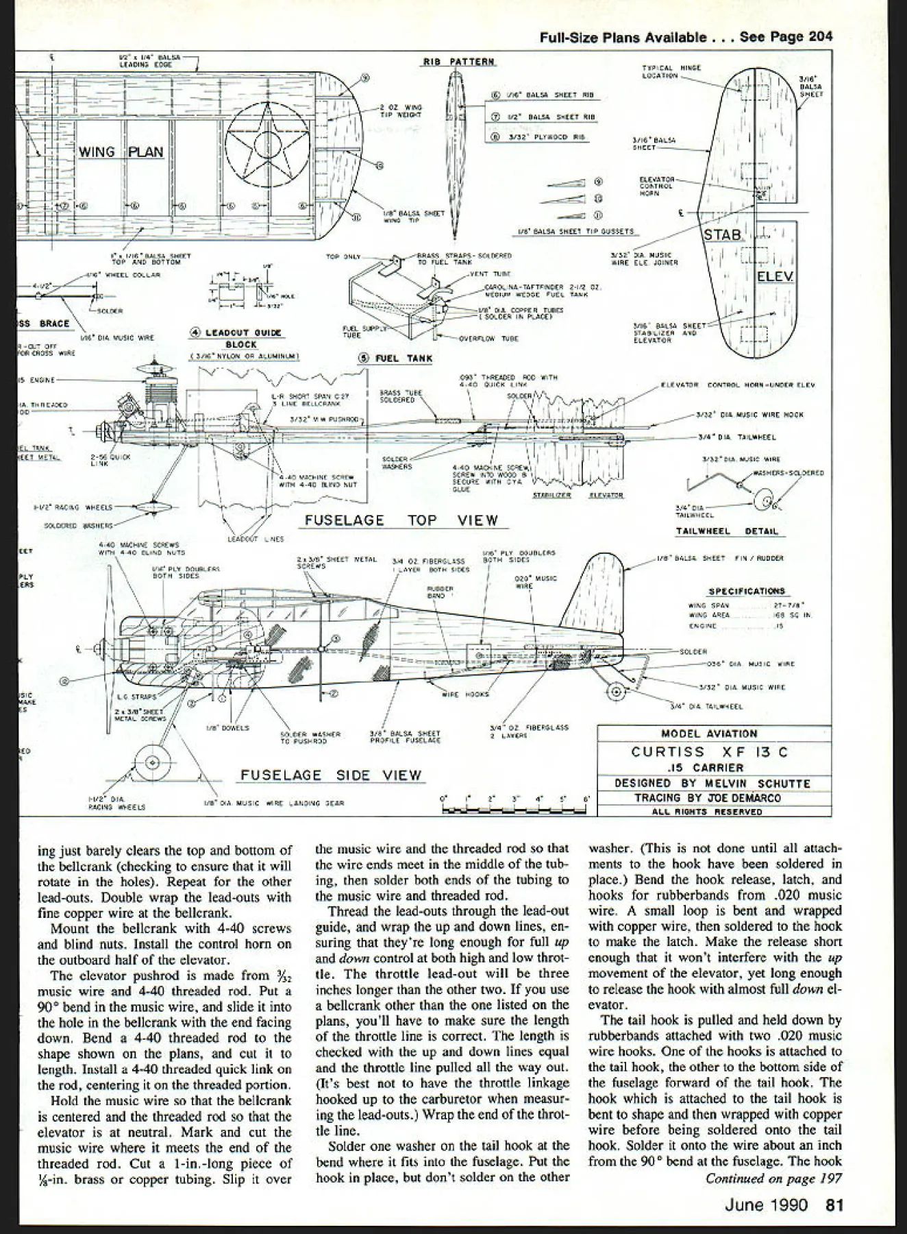
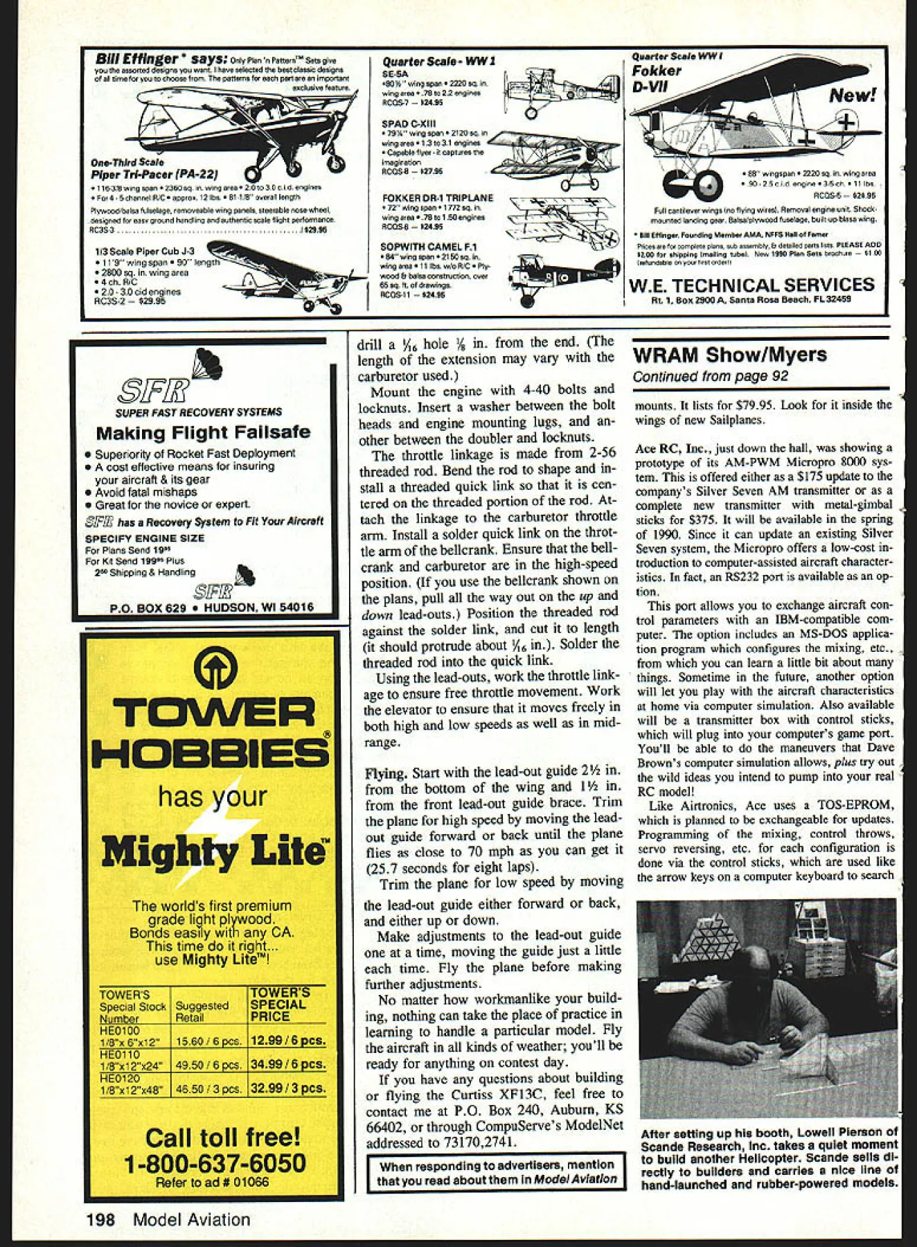

