
1/2A Marval
by Dan Berry
When Marvin Mace designed the original A/B Marval in the mid-1980s, he integrated the experience and success of his good friend the late Mark Valerius and Mark’s successful Rum Runner model series. The Marval design’s name is a combination of their first and last names.
As years passed, the Marval’s evolution benefited from Marvin’s extensive success, culminating in a model that shows the influence of two of the country’s top AMA Power fliers in the last two decades.
The design’s initial success was as a “locked-up” (no auto surface) airplane that climbed nearly straight up, with a transitional counterclockwise roll into a glide that literally hunted for lift. The Marval was so good that it was named the Large Gas Model of the Year in the National Free Flight Society’s (NFFS) 1993 Ten Models of the Year competition.
The latest iteration—the Super Marval—has shown its versatility as an auto-surface bunter, to the extent that the NFFS named it the Large Gas Model of the Year in 2007. The design is not lacking in heritage or bloodline.
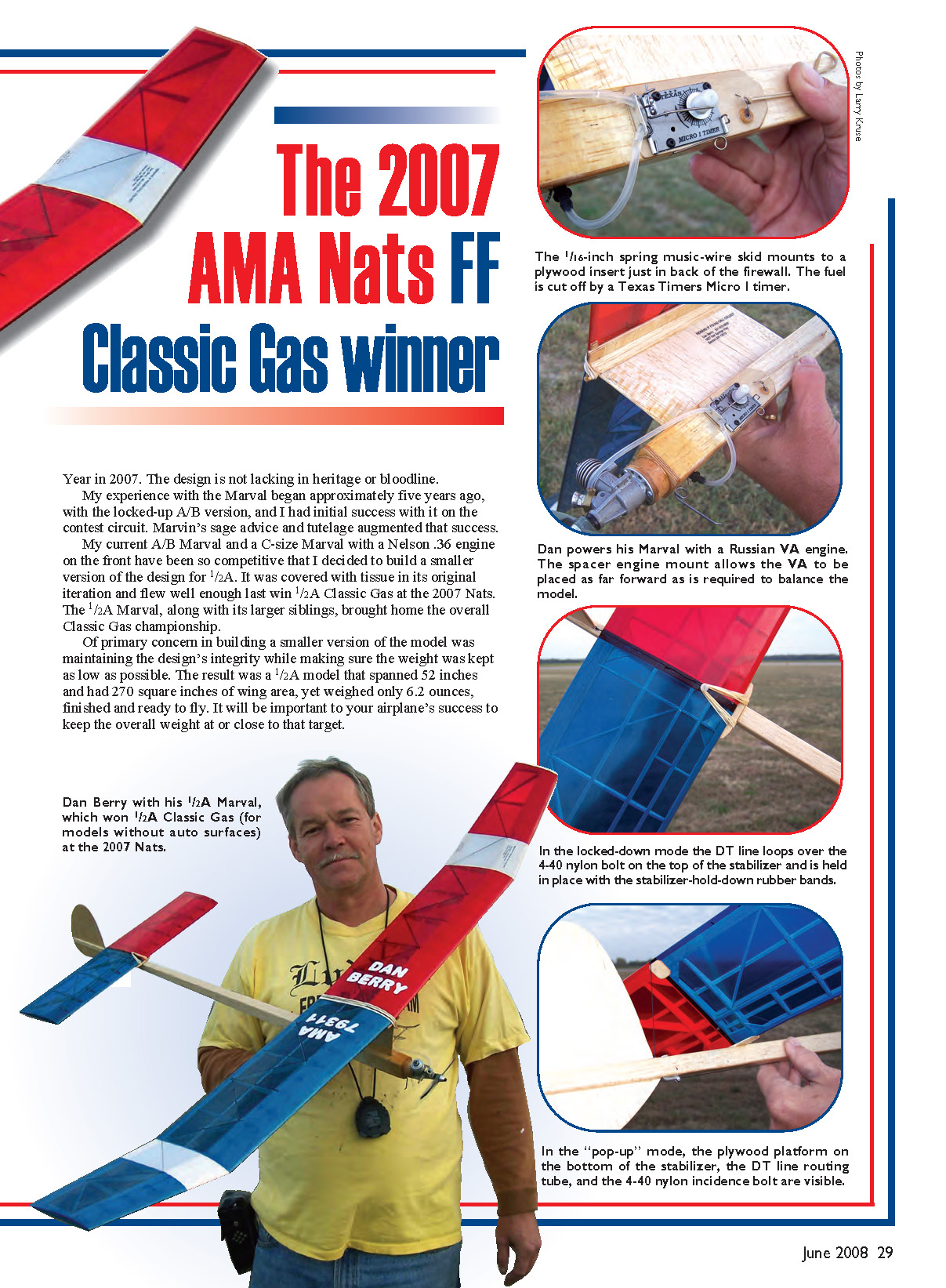
My experience with the Marval began approximately five years ago with the locked-up A/B version, and I had initial success with it on the contest circuit. Marvin’s sage advice and tutelage augmented that success. My current A/B Marval and a C-size Marval with a Nelson .36 engine on the front have been so competitive that I decided to build a smaller version of the design for 1/2A. It was covered with tissue in its original iteration and flew well enough last year to win 1/2A Classic Gas at the 2007 Nats.
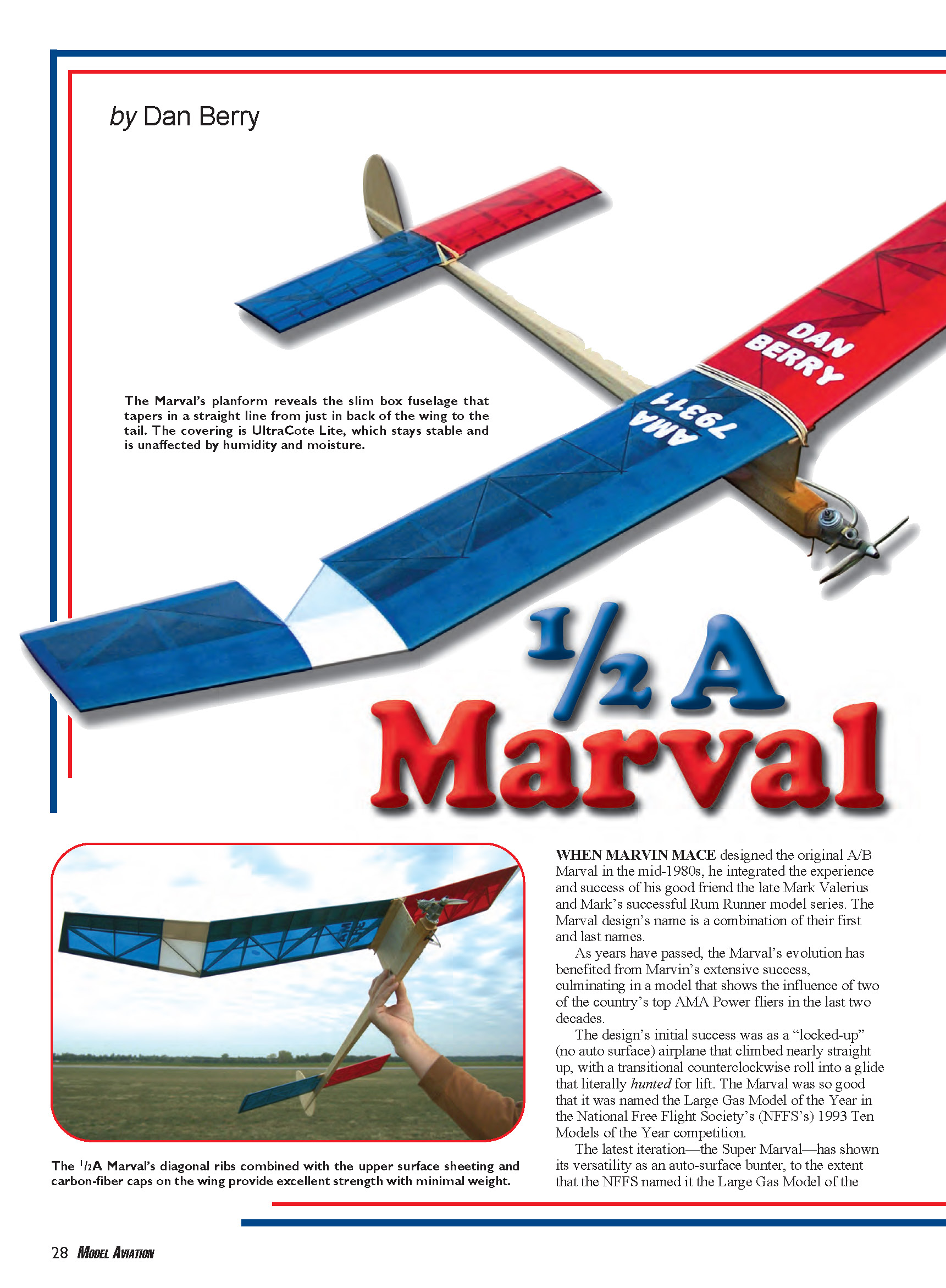
Of primary concern in building a smaller version of the model was maintaining the design’s integrity while keeping weight as low as possible. The result was a 1/2A model that spans 52 inches and has 270 square inches of wing area, yet weighs only 6.2 ounces finished and ready to fly. It will be important to your airplane’s success to keep the overall weight at or close to that target.
Some features incorporated into the smaller version to keep weight low without sacrificing toughness are the “box” fuselage, sheeting on only the top of the wing leading edge, the use of carbon-fiber rib caps, and an optional adjustable motor mount. These maintain the Marval’s reputation as a model that can take some knocks and keep flying, contest after contest.
Specifications
- Type: FF 1/2A Classic Gas
- Skill level: Intermediate to expert
- Wingspan: 52 inches
- Flying weight: 6.2 ounces
- Wing area: 270 square inches
- Length (without engine): 33.25 inches
- Stabilizer span: 19.375 inches
- Stabilizer area: 80.75 square inches
- Engine: 1/2A (.049 cu. in.)
- Construction: Balsa, plywood, carbon fiber
- Covering/finish: UltraCote Lite recommended
- Other: Engine cutoff and DT timer
CONSTRUCTION
Construction usually moves more rapidly if the model is “prekitted” before pinning or gluing anything. Wood for any sheet components should be 6-pound balsa and even lighter for the stabilizer ribs, if available.
Because this is not a beginner’s airplane, I’ll dispense with most “stick-to-stick” instructions and instead touch on those things that will ensure appropriate alignment and structural integrity.
Fuselage
One of the first decisions you need to make is what engine you will use in the model. Whether or not you employ the optional engine spacer mount will determine where the firewall blind mounting nuts will go and how the whole nose area will be set up, depending on the engine’s weight.
The goal is to have the completed model balance at the indicated CG without adding dead-weight ballast to either the nose or the tail. Of the two, because of the long tail moment it will be less of a problem (and potentially less weight) to add ballast to the tail.
To help in the engine-selection process, consider the weights of prospective power plants. As the photos accompanying this article show, I’ve used the VA engine in both of my models, and they required the optional engine spacer mount.
Unless you use a Cyclon, chances are that you will need the spacer mount and some adjusted thickness of the spacer after the airplane is completed to arrive at the correct CG with the engine installed. If you do decide on a Cyclon, you will be well served to make the wing a full geodetic structure as far as the diagonal ribs are concerned.
With the Marval’s high aspect ratio and the Cyclon’s additional speed and horsepower, it is imperative that the wing does not flex in the slightest. The additional diagonals, coupled with the carbon-fiber rib caps, will head off the problem before it emerges.
When construction begins, it’s crucial to build a straight fuselage. Since balsa parts have a tendency to stress-relieve even several days after being cut from a sheet, cut the blank for the fuselage top roughly 1/2 inch oversize in width (1/4 inch on each side). Let the blank sit for a couple of days while you work on some other phase of the model. Then draw a longitudinal centerline on the underside of the blank and cut the pylon and rudder slots.
You can build the fuselage upside-down on the fuselage top, with the former locations lightly marked on the centerline. The bottom of the fuselage is planked with cross-grain balsa from just in back of the firewall to approximately 1/2 inch in front of the rudder. The pylon and rudder must be lined up square with each other in all respects as they are installed.
The stabilizer platform can be tilted (right-side high) so that the stabilizer angle is roughly half the wing dihedral angle, for starters. Finish the completed fuselage with your favorite fuel-proofing method—as long as it's lightweight!
Flying Surfaces
The stabilizer presents no special problems other than it should be kept as light as possible and won't tolerate warps. Add the soft-balsa tips after construction is complete, and drill a hole to angle the 4-40 nylon bolt backward approximately 10° into the 1/4-inch-thick center rib. I drilled the hole, put a few drops of cyanoacrylate in it, and then tapped it for the nylon bolt after the cyanoacrylate cured.
The bolt can be removed until after the stabilizer is covered. It is at an angle for leverage purposes.
In rigging the DT, loop the DT line over the bolt head and then attach the stabilizer to the fuselage with rubber bands. The rubber bands will allow the stabilizer to pop up in DT mode and keep the DT line from coming off.
Wing
The wing is fussier but well worth the trouble in terms of lightness and rigidity. Frame up all four wing panels flat on the building board by pinning down the leading edges and trailing edges and adding the full-depth ribs, the top and bottom spars, and the half ribs. Do not install the diagonal ribs, dihedral and polyhedral ribs, top sheeting, or shear webbing at this time.
To arrive at the correct dihedral and polyhedral angles, block up each panel to its correct height and then carefully sand in the angle, much as you would on a Hand-Launched Glider wing. The difference is that you do not have a solid surface to work with—just a bunch of sticks—so proceed carefully.
Once satisfied with the fit, glue all four sections together and add the dihedral and polyhedral ribs.
Pin the left main panel flat and add 1/32-inch sheeting from the leading edge to the back of the main top spar. Note that the sheeting is only on the top and that the wood needs to be as light as you can find.
The rib diagonals are next. For now they do not need to be blended into the airfoil; it's okay if they're slightly tall.
Move to the right panel and prop up the leading edge 1/8 inch for the required washin. Support the LE and bottom spar with small incremental wedges along their entire lengths to avoid putting a bow in them when the 1/32 sheeting is added. The left main panel will be in the air over the building board and must be supported evenly and level with two 1/8-inch blocks under the LE and TE.
Once the right panel is dry, move back to the left panel. Pin it to the building board with a 3/32-inch shim under the rear of the most outboard rib to set in the required washout. During this operation the rest of the wing will be in the air and must be supported appropriately. The 1/32 sheeting and diagonals will build strength into the wingtip.
Follow the identical procedure with the right wingtip, including the 3/32-inch shim for washout, while continuing to block up and support the washin in the right main panel.
Add the rear 3/32-inch top spar across the entire span of the wing. Lay a straightedge along the existing main rib slots to mark the diagonal ribs and notch the ribs to accept the diagonal ribs. Once the spar is installed, use it as a sanding guide to bring the diagonals to the same shape as the main ribs.
Complete the wing structure by adding the gussets at the polyhedral joints, the 1/8-inch vertical shear webs between the main spars, and the plywood wing joiners. The gussets at the polyhedral joints are installed on top of the wing, providing a good surface for attaching the covering. These gussets will eliminate annoying wrinkles in the covering that typically show up near the TEs of polyhedral joints.
The wing is cosmetically completed by adding the tip blocks and then carving and sanding them to blend with the airfoil. When I was developing this 1/2A version of Marvin's Marval, I told him I changed the wingtips to their swept configuration because it made the model look "fast." Judging from the look on his face, I'm not sure he bought into it.
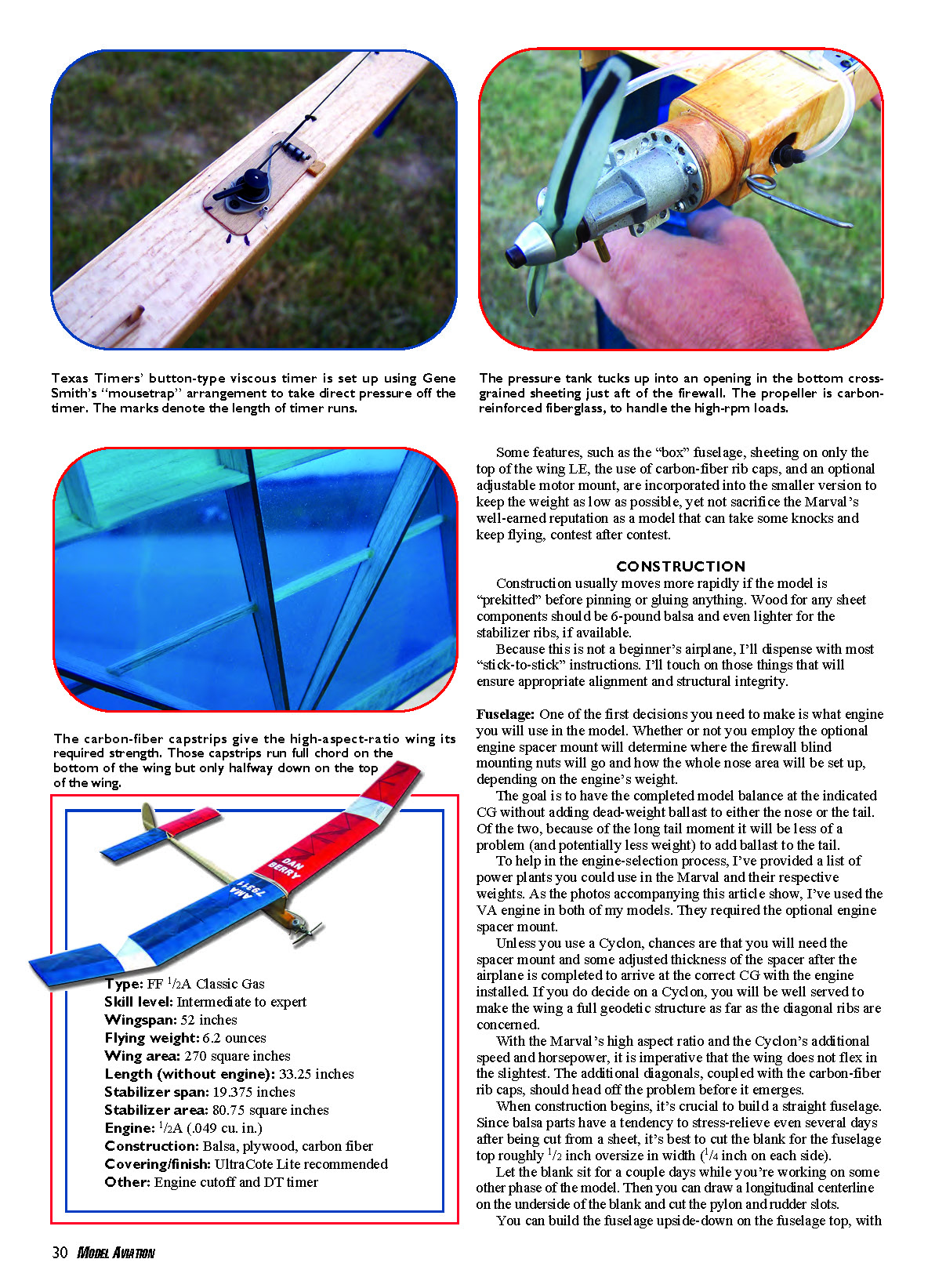
Sand everything smooth to eliminate the lumps the covering will magnify. At this point the wing has taken on considerable strength and torsional rigidity. To bring it up to where it needs to be for its high-speed power pattern, adding the carbon-fiber rib caps is a necessity.
If you are tempted to eliminate the carbon fiber, wad up the wing and throw it in the trash. That will save you the embarrassment of having to do it in front of your friends at the flying field!
To prepare to glue the capstrips in place, thoroughly dust off the wing. I used our vacuum cleaner's handheld brush nozzle to remove as much dust as possible, and then I wiped down the structure with a tack rag.
Prepare the .003–.005 carbon-fiber strips you will need by cutting them a bit oversize to roughly 3/32 inch wide. The exact width is noncritical; the wider strips are easier to handle and will ensure that contact is made with the rib surface without sliding off to one side or the other.
While you are cutting carbon-fiber strips, slice several small squares of Visqueen poly sheeting from a garbage bag or something similar. Use those pieces to protect your index finger from the cyanoacrylate as you press the strips in place.
The top capstrips are first. Pin down the left main wing panel. Lay a bead of medium cyanoacrylate on a diagonal rib, followed by a carbon-fiber cap. Press it in place with your Visqueen-covered index finger while blotting excess glue with a tissue as you go. I’ve found it best to “lock” the carbon-fiber strips in place by gluing the diagonals and then the main rib cap over the apex of the diagonal strips.
The caps on the top of the wing run from the front of the main spar down to roughly half the width of the TE. On the bottom of the wing they run the full width on all ribs on the main panels and the full width on the tip diagonals only.
As the caps are applied, they can be precut to length or trimmed as they are installed using a pair of Dykes or side-cutter pliers. Close-up photos of the wing top and bottom should be helpful when installing the capstrips.
As you move from one wing panel to another when applying the top capstrips, be sure to block up the panels as you did in the previous steps to ensure that the washin in the right wing and the washout in the tips remain as they are supposed to be. Once you glue the top capstrips in place, the bottom capstrips are done “in the air,” without the need for the panels to be pinned down.
To see if all the capstrips are stuck down as they should be, hold the wing up to one ear and gently twist it back and forth. You’ll be able to hear the strips that pop up and then see those that came loose or were never glued down properly. Once all the capstrips are locked in place, sand the entire wing with 220-grit sandpaper.
Go back to each rib and vertically sand the caps to their final width. Use an emery board or similar small sanding block to bring the 3/32-inch width down to the finished 1/16-inch rib thickness.
Cover the flying surfaces with an iron-on covering such as UltraCote Lite, traditional tissue and dope, or Polyspan Lite. Stay away from the heavier iron-on coverings; they will add nothing but weight.
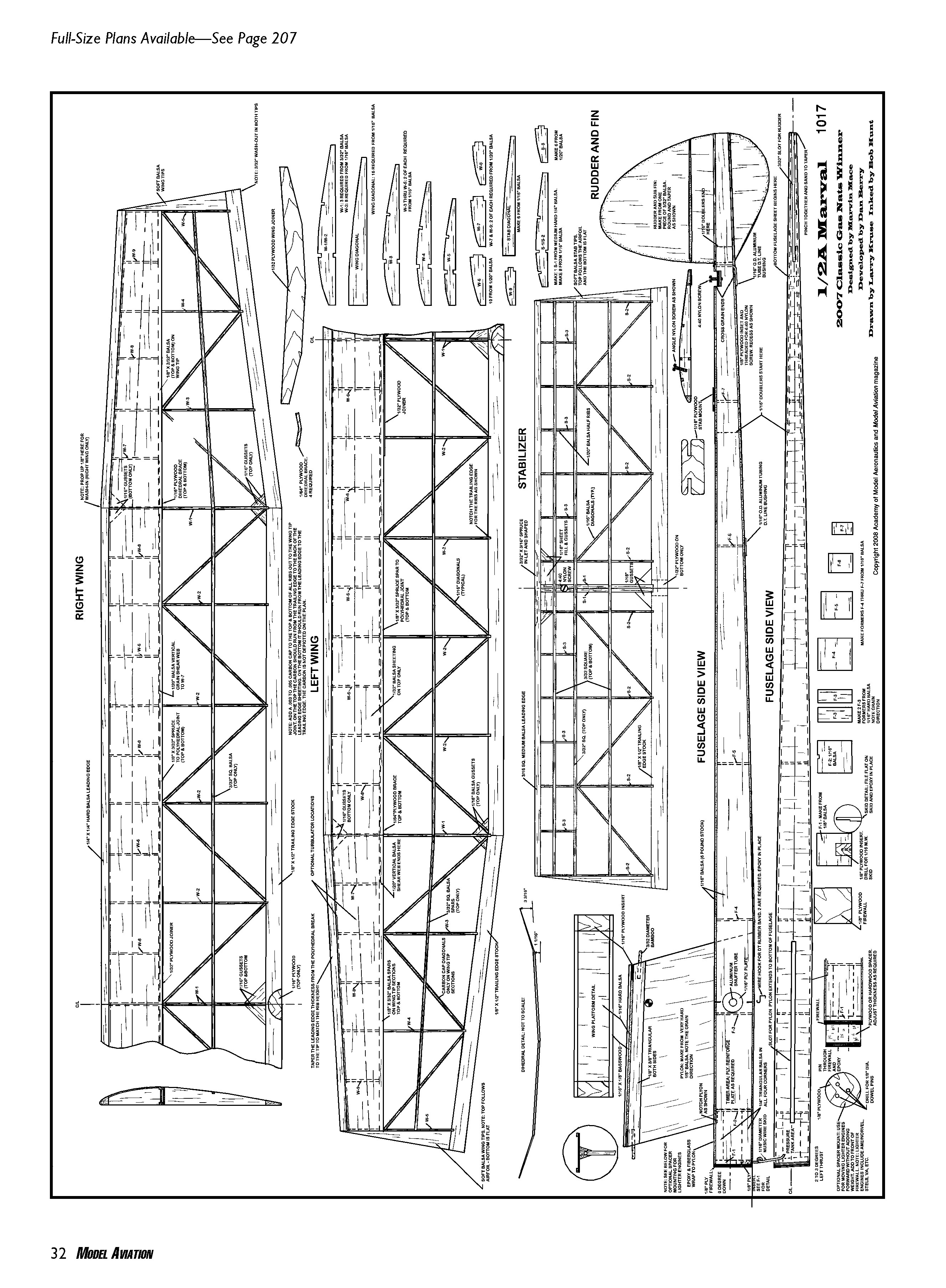
1/2A Marval
2007 Classic Gas Nats winner
Designed by Marvin Mace Developed by Dan Berry Drawn by Larry Kruse Illustrated by Bob Hunt
Right Wing
Left Wing
Stabilizer
Rudder and Fin
Fuselage Side View
Flying
The 1/2A Marval must balance as shown on the plans. I hope that little or no weight will be needed. If it is, do not hesitate to add it. This model is quick out of the blocks and won't tolerate being out of balance for very long.
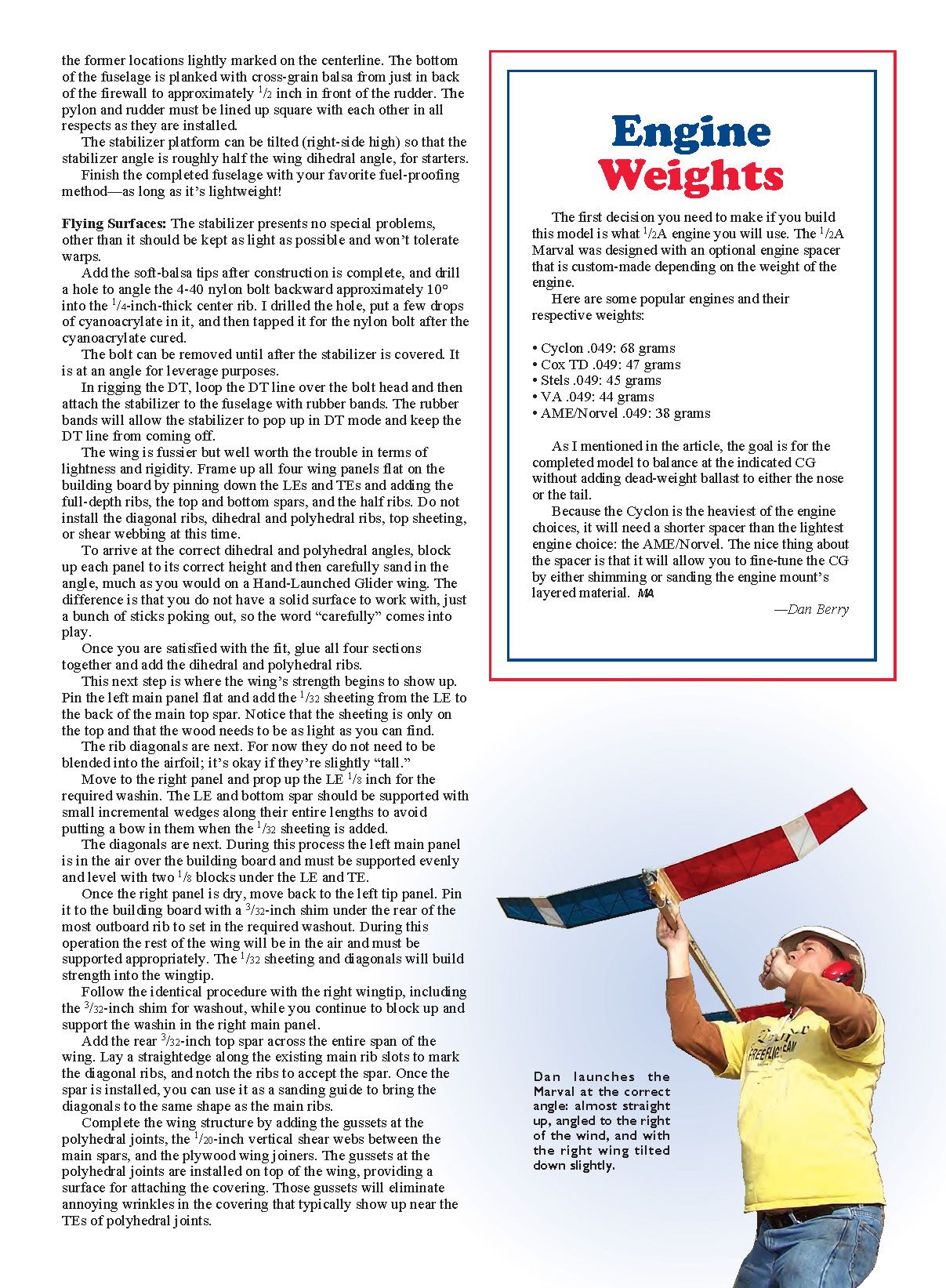
First flights should be under full power over the proverbial tall-grass field we all have, but with no more than a two- to three-second engine run. The correct launch angle is nearly vertical, with the right wing tilted down a bit and the model facing to the right of the wind.
Do not launch the Marval to the left of the wind! A right turn with the right wing dipping indicates too much stabilizer incidence. Reduce the incidence with a half turn of the stabilizer incidence bolt on successive flights until the model remains nose-up with a slight turn to the right.
If the power pattern looks safe, increase the engine run to four to five seconds. You may need to add a small 1/4 x 1/32-inch tapered balsa wedge to the left side of the rudder to get the model to climb vertical and begin its counterclockwise roll induced by the right-wing washin. Add or subtract rudder shims as required.
Once the power pattern is repeatable and satisfactory, you can tighten the glide turn, if necessary, by adding 1/64-inch plywood shims under the left wing. Shimming the wing instead of the stabilizer is more precise and doesn't affect the power pattern.
For optimum glide, add a small amount of clay or lead tape to the tail to get the slow, nose-up, thermal-hunting glide that is the Marval's trademark.
Good luck with your version of Marvin Mace's classic! Address any correspondence or questions about building and flying the 1/2A Marval to me:
Dan Berry 1827 Hot Springs Hwy. Benton, AR 72019 [email protected]
Sources
- Texas Timers — (423) 282-6423 — www.texastimers.com
- Kitting It Together — www.kittingittogether.com
- FAI Model Supply — (570) 882-9873 — www.faimodelsupply.com
Transcribed from original scans by AI. Minor OCR errors may remain.

