
1/2 A Time Machine - 2007/07
DESIGNED BY JOHN FERRER AND BOB HATCH TEXT BY BOB STALICK
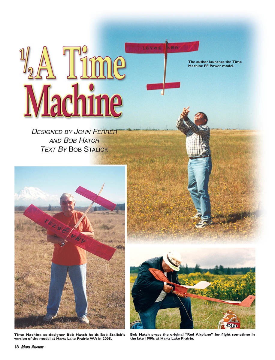
I first saw the Time Machine fly in the early 1990s at an FF contest at Harts Lake Prairie, Washington. Bob Hatch—one of its co-designers—was putting up flight after flight and max after max with it. The pattern was flawless, with a loose right turn in the rapid climb and a smooth right turn into the glide. And what a glide! It seemed just to soar. Thermaling was a cinch. Then on one of the max flights the model did not DT and was in another thermal. It moved downwind and climbed higher and higher. The field at Harts Lake Prairie is surrounded by trees and creeks—not a good place for a fly-away. Bob and others took off running after the airplane, but it was gone.
I asked Bob about the Time Machine and he filled me in on how it was designed, with two people at different corners of the West Coast putting their heads together to come up with the model. He said: “The late John Ferrer was a member of the Balsa Bugs and was very active in promoting building and flying, especially with new people, both in and outside the club roster. His major problem was convincing people competitive models could be built in a relatively short time.
“To prove his point, he designed the wing and stabilizer for the model that would become the Time Machine and led building sessions during regular club meetings. His goal was to have people complete a wing and stabilizer during a club meeting, and it happened often.
“I flew at the USFFC [US FF Championships] at Taft [CA] sometime in the late 1980s, and I lost my 1/2A Hydro Star in a boomer. There was a contest coming up at Harts Lake Prairie (in Washington), and I needed an airplane.
“During a business trip to Los Angeles, I was able to procure a built-up wing and stabilizer combo from one of these club building sessions. I covered it, built a fuselage, mounted a Tee Dee .049, finished up the model, and four days later test flew it at Sepulveda Basin. Thanks to John’s contribution, the airplane built up faster than anything I’ve done before or since.
“During the airplane’s tenure in my hangar, it performed well, but did not take home a lot of hardware, usually due to my ineptitude. It did win a first at a Harts Lake Prairie event where it DTed downwind, and I could not find it. Later, the model was returned to me by another flier who happened to find it.
“The original model was lost in a boomer thermal in the 1990s at Harts Lake. I was tracking it with binoculars, saw it DT, and watched it continue up and out of sight heading southwest. It was the best AMA model I ever had."
Time went by and I continued to think about Bob Hatch's model, which he had been calling the "Red Airplane." As FF competition models became more sophisticated and full of gadgets, the Red Airplane seemed an anachronism. However, the AMA Free Flight Contest Board created the Classic Gas event, allowing models without variable surfaces to be flown in their own classes. The Red Airplane became a candidate for competition once more.
When the AMA Classic Gas rules went into effect, I began harassing Bob Hatch for a set of Red Airplane plans. After some procrastination I received a set of rough-draft plans and an extensive set of drawings and commentary from him. It was all I needed to build the model. Bob got an early start on his new airplane and had it constructed, without covering, before Christmas. I started mine in January.
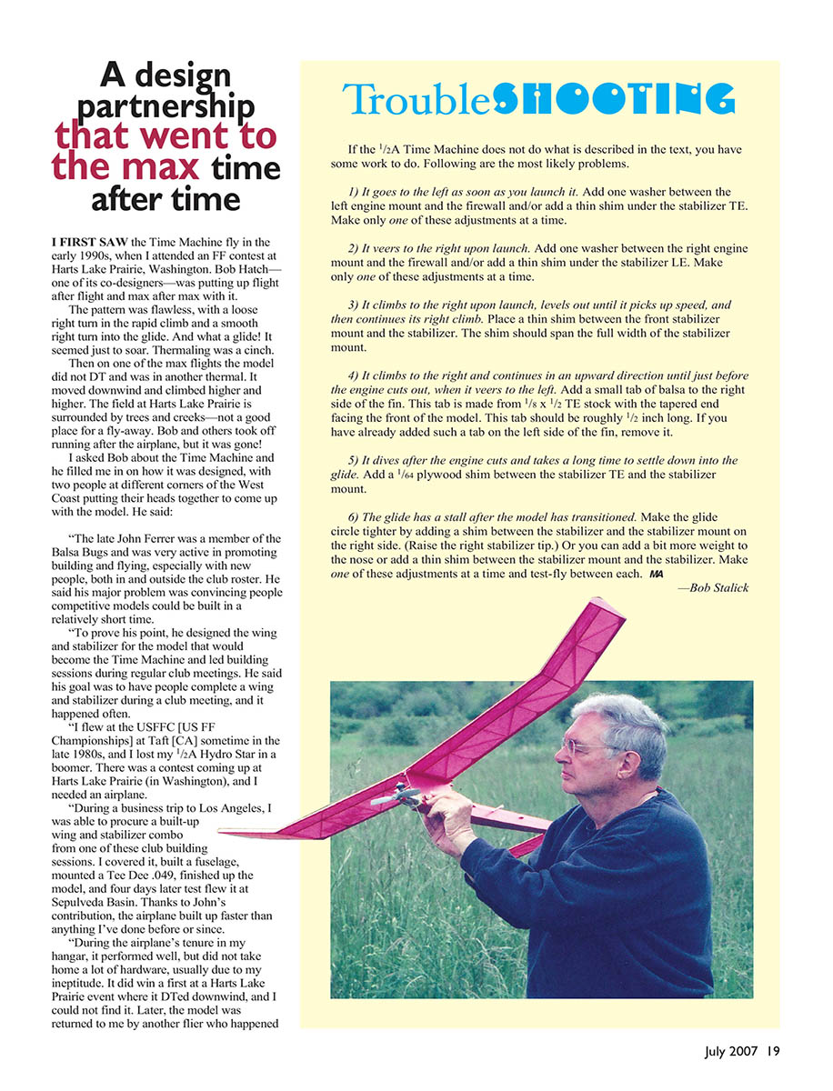
I was surprised by how well the model went together. It built quickly, and the result was a light, stiff airframe. I covered mine with Microlite—a material that was new to me—and Bob covered his with Japanese tissue. The final plans were drawn by John Anderson, who used the three-views and the notes and drawings Bob provided to produce CAD plans.
I built my model from the Anderson plans, with changes and errors noted during construction. I sent all those modifications to John for inclusion in the final plans copy. The plans presented here were flight-tested in the construction of a contest-level FF model.
Before gluing parts together, decide on engine, engine mount, fuel system, timer, and DT system. The model has been built with Cox Tee Dee .049/.051, Stels .049, Norvel (AME) .049, and current Russian or Chinese .049s. For tank or long-beam mounts, the firewall is immediately in front of and below the wing LE and pylon. Hayes-style or Texas Timers backplate mounts require extending the front of the fuselage forward by 0.6 inch. Choose hard tank or pressure/tubing system, and select timers (Texas Timers products recommended: Texas Max III for built-in DT, Texas Mini for fuse/viscous timers).
Nearly all ribs are diagonal geodetic types—lightweight and warp-resistant. Use lightweight C-grain balsa for ribs (about 6 lb density); fuselage sides 7–8 lb stock. Pylon can be slightly heavier. Fin is 3/32 C-grain lightweight. Bulkheads and formers can be sturdier stock; LEs of wing and stabilizer can be sturdier as well.
Troubleshooting
If the 1/2A Time Machine does not perform as described, the following are the most likely problems and fixes. Make only one adjustment at a time and test-fly between changes.
- It goes to the left as soon as you launch it.
- Add one washer between the left engine mount and the firewall and/or add a thin shim under the stabilizer TE.
- It veers to the right upon launch.
- Add one washer between the right engine mount and the firewall and/or add a thin shim under the stabilizer LE.
- It climbs to the right upon launch, levels out until it picks up speed, and then continues its right climb.
- Place a thin shim between the front stabilizer mount and the stabilizer. The shim should span the full width of the stabilizer mount.
- It climbs to the right and continues upward until just before the engine cuts out, when it veers to the left.
- Add a small tab of balsa to the right side of the fin. This tab is made from 1/8 x 1/2 TE stock with the tapered end facing the front of the model. The tab should be roughly 1/2 inch long. If you have added a similar tab on the left side, remove it.
- It dives after the engine cuts and takes a long time to settle into the glide.
- Add a 1/64-inch plywood shim between the stabilizer TE and the stabilizer mount.
- The glide has a stall after the model has transitioned.
- Make the glide circle tighter by raising the right stabilizer tip: add a shim between the stabilizer and the stabilizer mount on the right side. Or add a bit more nose weight or add a thin shim between the stabilizer mount and the stabilizer. Make only one change at a time.
— Bob Stalick
Specifications
- Type: FF
- Wingspan: 45.75 inches
- Weight: 190 grams without fuel
- Wing area: 295.75 square inches
- Length: 39.625 inches
- Engine: Tee Dee .049 (typical)
- Construction: Balsa with plywood reinforcement
- Covering/finish: Japanese tissue or equivalent (Microlite also used)
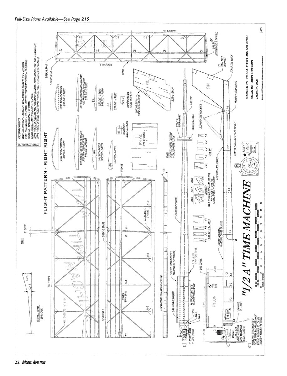
Construction
Stabilizer
- Roll the plans out on your building surface and secure them. Put waxed paper over the plans.
- Pin the LE in place. Trim a piece of 1/8 x 1/2 TE stock down to 3/32 x 3/8 by cutting 1/8 inch off the thick part; pin this in place as the TE.
- Fit all S-1 ribs in place; trim TE or move TE closer to LE to obtain snug fit. Glue ribs with Sig-Bond.
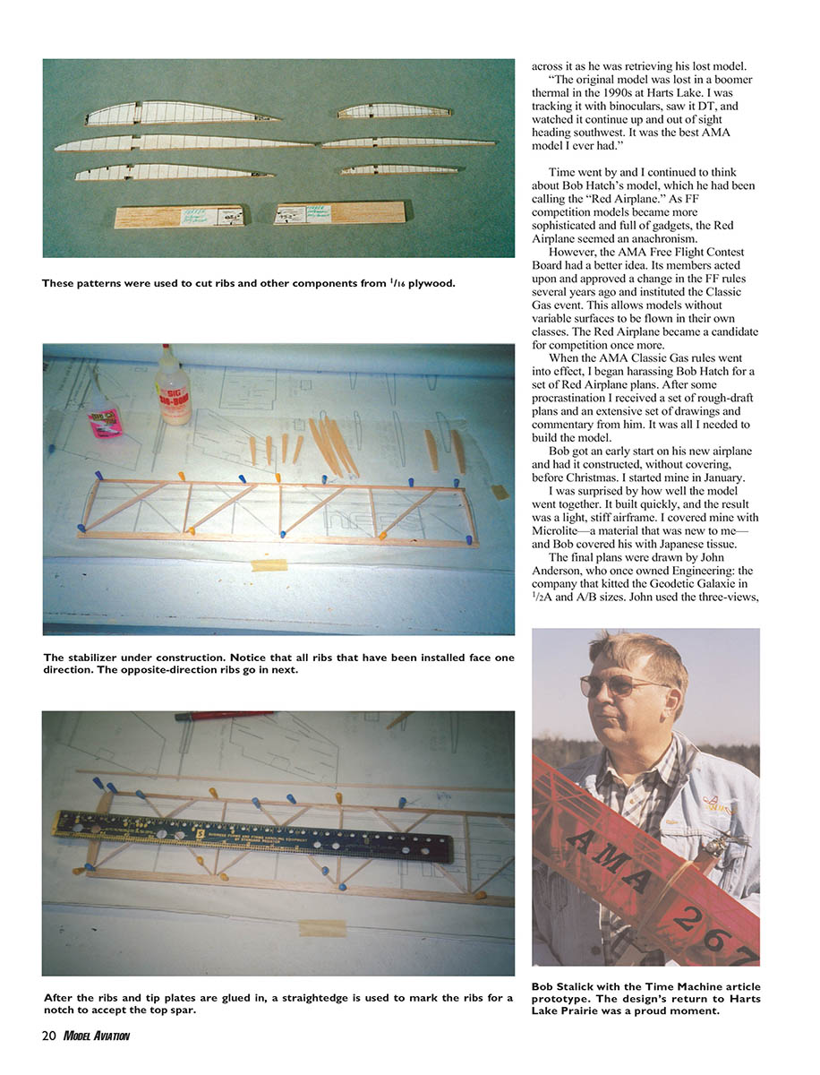
- Dry-fit four geodetic ribs at the same angle along the span. Sand mating angles on each rib for good joints with LE and TE. Glue in place.
- When dry, sand LE and TE on remaining geodetic ribs and cut interlocking slots where ribs intersect. Glue with Sig-Bond where ribs intersect and at LE and TE.
- Fit and glue the angled stabilizer tip. Notch geodetic ribs to accept the 3/32 x 1/8 top main spar and glue it in place.
- Adhere S-2 ribs and glue 1/16-inch diagonal gussets as shown. Notch ribs and glue 3/32 x 3/32 front top spar. Allow stabilizer to set overnight.
- Unpin, notch ribs to accept the main spar on the underside, let dry, then shape and sand the LE. Use fine sandpaper to remove rough spots. Set aside for covering.
Wing
- Build each wing panel like a wider stabilizer. Cut LEs and TEs to size and pin in place.
- Note the angle where wingtip panel joins main panel—this provides washout after covering.
- Fit and glue straight ribs (W-1). These are canted at dihedral joints—use the template on the plans and transfer angles onto 1/16 balsa to obtain correct cant.
- Glue diagonal ribs in one direction first, then the opposing direction.
- Fit tip pieces, notch ribs, and glue top main spar and two turbulator spars. Glue W-2 ribs and add gussets. Allow to dry overnight.
- Remove each wing panel, match tip panels to main panels, sand mating surfaces to snug fit.
- Pin main panels to the board, block up the tip panels so each has a dihedral equal to 2.6 inches (2 5/8). Apply Sig-Bond or epoxy to mating surfaces and pin in place; allow eight hours to set.
- Join main panels, block one panel to 2.6 inches dihedral, glue, and cure for at least eight hours.
- Remove from plans, notch underside of ribs to accept bottom spar and glue. Center section has 1/8 x 1/4 tapered doublers—notch center ribs to accept doublers and glue.
- Add remaining gussets and glue in 1/32-inch vertical webs for strength using cyanoacrylate and microballoons to fill gaps.
- When cured, shape the LE and sand any bumps. Set aside.
Fuselage
- Kit all parts before assembly. Cut firewall parts; face the front firewall with magnesium or aluminum sheet if available (allows thrust adjustment); otherwise use 1/16 plywood.
- Notch one firewall piece to accept 1/16-inch-diameter landing skid. Bend skid as shown, epoxy parts together with skid, clamp, and cure.
- Clamp engine mount to firewall, drill through, place 2-56 bolts through firewall, attach 2-56 blind nuts, snug them up and epoxy blind nuts solidly to back of firewall. Allow to cure.
- Cut the fin from lightweight 3/32 C-grain balsa. Glue 1/32 x 3/32 basswood strip to LE, TE, and tip. Sand fin to a symmetrical airfoil shape, thinning toward tip.
- Cut pylon pieces from medium-weight 3/16 C-grain balsa, glue together, sand the LE to round cross-section and taper the TE.
- Cut wing platform from 3/32 balsa with grain running side to side. Glue 3/32 hard balsa or spruce runners on top of each side of the platform.
- Cut fuselage formers from firm balsa and label them.
- Use 1/16 balsa for fuselage sides (7–9 lb stock, target 12–15 grams). Draw fuselage sides and pin to plans top-down. Block fuselage off the plans with scraps to ensure straightness.
- Epoxy firewall in place with landing skid pointing up and away from the building board. When cured, glue in formers F-4 through F-8 and remove from plans.
- Glue formers F-1 through F-3 to either side of the pylon and fit pylon in place. Remove pylon material between F-1/F-2 and F-2/F-3 to lighten or to make space for a tank; leave sufficient material to support the formers.
- Use Sig-Bond to adhere the formers to the inside of the fuselage. Pin formers in place, ensuring pylon height above the fuselage matches LE and TE. Let dry.
- Carefully align and glue the fin in place with cyanoacrylate—ensure it is centered and not leaning.
- Glue scrap tail blocks (1/8 inch thick) at each side of the fin/fuselage side joint with Sig-Bond. Pin and sight down the fin to assure alignment before curing.
- Glue top of fuselage with 1/32 medium balsa, grain side to side.
- Install 1/16 plywood rear stabilizer mount. Drill a 1/8-inch hole in center and glue it immediately in front of the fin.
- Insert a yellow Nyrod tube into this hole with excess exiting the bottom of the fuselage; bend Nyrod to a shallow angle and have it exit the left side of the fuselage. Heat with a soldering iron if necessary and secure with cyanoacrylate.
Fuel Tank
- Skip this if using an external tank or tank mount.
- For a hard tank: mount it with fill tubes exiting the right side of the fuselage and pickup tube exiting just in front of or beneath the motor. Mount the tank directly behind the timer between formers F-1 and F-2 (in the area where pylon material may have been removed). Secure with epoxy or silicone adhesive.
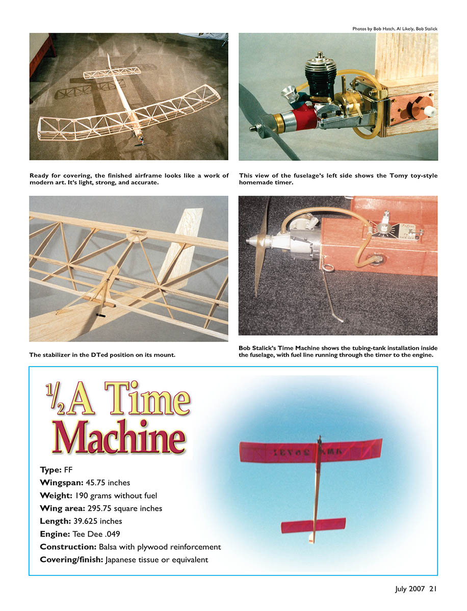
- For a tubing tank: locate it between F-1 and F-2; have the tubing exit the underside of the fuselage. Fuel-proof the inside fuselage in this area with several coats of clear epoxy paint. Reinforce the exit hole—use a hard plastic insert with ~0.5-inch interior opening.
Covering the Fuselage Bottom
- Cover the bottom with cross-grain 1/32 balsa like the top. Use Sig-Bond and pin in place; avoid warping the fuselage.
- If using a tubing tank, reinforce the area under the tank; the author added 1/64 plywood running the width of the fuselage from firewall to F-2 to create the floor for tank insertion.
- After assembly cures, carve and sand the fuselage top and bottom flush with the sides. Remove lumps and excess glue.
- Glue wing mount onto the pylon centered and aligned. Install wing dowel to 1/4 inch depth.
- Mark stabilizer LE location and install front stabilizer mount. When fitted, the stabilizer should show a slight right tilt (right tip higher than left). The right stabilizer tilt should roughly equal the right main panel angle.
Covering
- Choose Microlite/plastic covering or Japanese tissue.
- For Microlite: follow package instructions. Spritz water on the wing when applying AMA numbers to prevent adhesive from grabbing.
- For Japanese tissue/dope:
- Apply clear nitrate dope to all structures that will touch tissue—at least three base coats, sanding between coats.
- Apply tissue using thinner for adhesion, spritz water on open structures and let dry.
- Apply two coats of thinned nitrate dope, trim with tissue AMA numbers, apply three or four more coats of clear dope, then add one or two coats of AeroGloss Fuel Proofer or equivalent.
- If not covering the fuselage, fuel-proof it with at least two coats of epoxy paint. If covering with tissue, the final coat should be clear epoxy for fuel-proofing.
Final Assembly
- Install wire pieces in stabilizer and fuselage.
- A hold-down hook is glued (cyanoacrylate) to the center rib of the stabilizer after covering. The DT line runs through the yellow Nyrod, through the hole in the rear stabilizer mount, through a hole drilled into the stabilizer TE, and loops around the hold-down hook.
- The DT line is held when the rubber band is attached to this hook. A similar hook is mounted on top of the fuselage in front of the stabilizer mount to assist raising the stabilizer under DT.
- The hook alongside the fuselage under the pylon is the other end of the DT line; the line has a wire loop where the rubber band is placed to tension the line and hold the stabilizer down.
- A snuffer tube is located under the rubber band; mark the spot and drill a 1/16-inch hole through the fuselage. Cut a piece of 1/4-inch OD aluminum tubing and cyanoacrylate-glue it into place. A snuffer tube is not required if using a DT timer, but the DT line must align with the timer arm.
- Set the DT line so that when the timer or fuse releases it, the stabilizer TE pops to approximately 60°. Use a small washer or knot to limit the amount of line released to approximate this angle.
- Align the wing on the wing mount so it fits the same location flight after flight. Use a 1/4-inch-diameter dowel split in half; place halves on the wing adjacent to the mount, adhere with a minute amount of cyanoacrylate, then remove the wing and securely glue the dowels in place. Seal with fuel-proofer.
- Complete an AMA model-identification sheet and adhere it in an obvious place on the model.
Flight Preparation
- Ensure engine and timer run and that the DT system functions (timer shuts off engine and releases stabilizer).
- Balance the model: plans show balance point at 80% (5/8 inch from the wing LE). Mark this on either side of the pylon and support the model at those points.
- If tail-heavy, add weight to the nose by moving the engine forward using rings of aluminum sheet cut to the engine mount size. If nose-heavy, add lead to the tail behind former F-8 (flat lead sheets or a glued penny).
- If within 1/4 inch of the CG, no change is necessary.
Test Flights
- Find an area with grass about 6 inches tall. Hold the model above your head, face into the wind, and launch with a slight downward glide angle aiming at a point ~25 feet away.
- The model will probably dive initially. Start by placing a strip of 1/64-inch plywood under the stabilizer TE adhered to the rear platform with cyanoacrylate. Glide again and add more 1/64-inch strips until the glide is floating, nearing a stall (original models needed from 1/64 to 1/16 inch).
- The model should have a floating glide and turn to the right. Ensure stabilizer right tip is higher than left and approximately equal to the right main panel angle. If it does not glide with a slight right turn, add stabilizer tilt by gluing a small piece of 1/64 plywood to the right side of the front stabilizer mount. Place two small trim tabs on the left side of the fin to reduce tight right climbs if necessary—wait until after powered tests before adding these tabs.
Power Test Flights
- Test away from others. Assemble with rubber bands, start the engine without pegging, set timer for a short run (2–3 seconds) or DT fuse short (or timer ≤30 seconds).
- Launch at ~45° into the wind. The Time Machine should climb quickly to the right in a loose spiral, making one turn on the way up, then transition into a floating right glide with circles roughly 200+ feet.
- If initial climb and glide are safe, gradually increase engine run times and lean the engine. If all goes well, increase engine run to the full seven seconds allowed in Category III Classic Gas.
- Improve power/performance by choosing efficient props and adjusting fuel nitromethane content.
The Time Machine is an extraordinarily competent 1/2A Gas design that should be built as lightly as possible. It meets Classic Gas event criteria (no auto surfaces) and can be competitive in Category II or III events. We are interested in your experiences with this design. Enjoy it—and good luck. Just put it in a thermal and wait until it DTs.
Bob Stalick [email protected]
Sources
Support your local hobby shop for most materials. If you need mail-order sources:
- Texas Timers (timers, engine backplate mounts, fuel fittings, tubing, tanks)
Texas Timers 3317 Pine Timbers Dr. Johnson City, TN 37604 (423) 282-6423 www.texastimers.com
- Campbell's Custom Kits (engines, timers, covering, props, DT fuse, balsa, FF accessories)
Campbell's Custom Kits 31 Fletcher St. Anderson, IN 46016 (765) 683-1749 www.campbellscustomkits.com
- Sig Manufacturing Co. (balsa, hardwood, aircraft plywood, Norvel engines, covering, nitrate dope)
Sig Manufacturing Co. Box 520 Montezuma, IA 50171 (641) 623-5154 www.sigmfg.com
No additional running article text appears on the plans page; the page contains the full-size plans and specifications for the 1/2A Time Machine (plans, labels, and drawing notes).
Transcribed from original scans by AI. Minor OCR errors may remain.

