
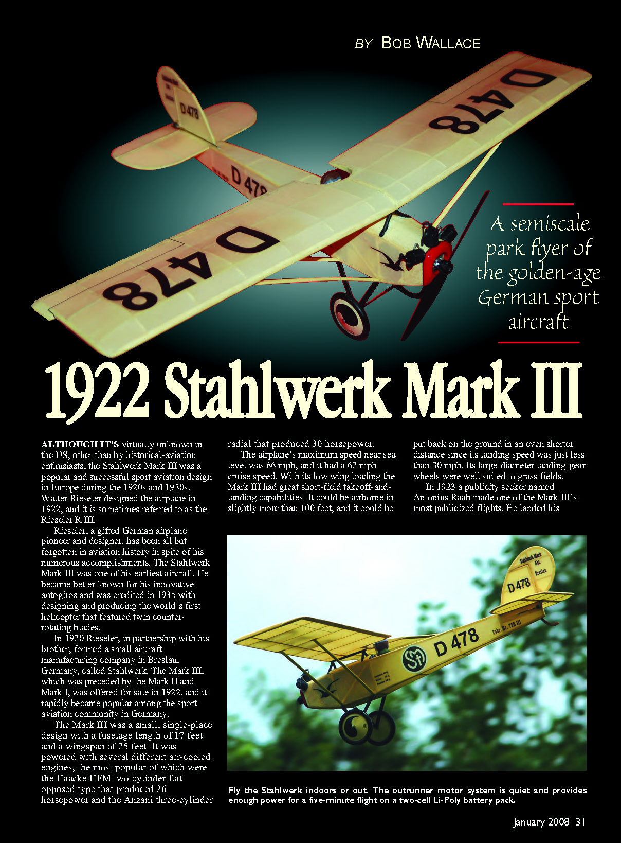

1922 Stahlwerk Mark III
By Bob Wallace
A semiscale park flyer of the golden-age German sport aircraft
Although it's virtually unknown in the U.S., other than by historical-aviation enthusiasts, the Stahlwerk Mark III was a popular and successful sport-aviation design in Europe during the 1920s and 1930s. Walter Rieseler designed the airplane in 1922; it is sometimes referred to as the Rieseler R III.
Rieseler, a gifted German airplane pioneer and designer, has been largely forgotten in aviation history despite numerous accomplishments. The Stahlwerk Mark III was one of his earliest aircraft. He later became better known for innovative autogiros and was credited in 1935 with designing and producing the world's first helicopter that featured twin counter-rotating blades.
In 1920 Rieseler, in partnership with his brother, formed a small aircraft manufacturing company in Breslau, Germany, called Stahlwerk. The Mark III, preceded by the Mark I and Mark II, was offered for sale in 1922 and rapidly became popular among Germany's sport-aviation community.
The Mark III was a small, single-place design with a fuselage length of 17 feet and a wingspan of 25 feet. It was fitted with several different air-cooled engines, the most popular being the Haacke HFM two-cylinder flat-opposed (26 hp) and the Anzani three-cylinder radial (30 hp).
Performance: maximum speed near sea level about 66 mph, cruise speed about 62 mph. With its low wing loading the Mark III had excellent short-field takeoff-and-landing capabilities: it could be airborne in slightly more than 100 feet and could be put back on the ground in an even shorter distance, with a landing speed just under 30 mph. Its large-diameter landing-gear wheels were well suited to grass fields.
In 1923 a publicity seeker named Antonius Raab made one of the Mark III's most publicized flights by landing his aircraft on the Unter den Linden, a main thoroughfare in Berlin. He was promptly arrested. At least one Mark III still exists and is on display at the Arlanda Aerospace Museum in Stockholm, Sweden.
I selected the Stahlwerk Mark III as an RC modeling project because it's unique and its dimensions and planform promised a model that would be easy to build and fly with good flight characteristics. Perhaps RC modelers who have never built a stick-and-tissue-type model will find this construction project of interest. It uses simple, proven building methods that require no unique tools or specialized skills. Older modelers who grew up building Comet and Megow kits may find the Mark III a pleasant trip down memory lane.
The intent in designing this model was to keep it simple, using inexpensive and readily available construction materials most hobby shops stock. My Stahlwerk Mark III is powered by a Baby Bullet Double Cool Wind brushless outrunner motor from CustomCDR.
CONSTRUCTION
As with any plans- or scratch-building project, it helps to fabricate all shaped or formed parts before you begin assembling the basic structure. That way construction proceeds more smoothly and without interruption.
I did not prepare a list of required materials because most modelers with some building experience will have most, if not all, of the various-size wood pieces in their spare-wood supply. Some sizes indicated do not require a full sheet, and the hardware needed is minimal.
Many modelers with built-up construction experience know that using a balsa stripper greatly simplifies material acquisition. With this tool, all the stick stock can be cut easily from sheet stock to any custom width needed. I used a Jones balsa stripper, which is considered the Rolls-Royce of balsa strippers, but an inexpensive version such as Master Airscrew's will work fine.
The number of shaped or formed parts required to construct a Stahlwerk Mark III is minimal. Since the wing is constant-chord, cutting the 11 balsa wing ribs is quick if you first make a master template from a scrap piece of 1/32 plywood, thin sheet aluminum, or plastic.
The motor-mount former is cut from 1/8 light plywood. Its height and width may vary depending on motor type and how the former is positioned in the nose.
Other shaped parts needed: 1/16 plywood tail skid, two 1/16 plywood landing-gear mounting crossbraces, three 3/32 sheet top fuselage formers, and a 1/16 plywood wing-spar brace.
Main components are constructed directly over the plan sheet placed on a flat building surface. Place a sheet of clear vinyl plastic (backing from heat-shrink covering materials works well) or waxed paper over the plans to permit easy separation of assembled parts from the sheet.
Wing
To construct each wing panel, pin the 1/8 x 1/4 main spar in place along with the 1/8 x 3/8 trailing edge (TE). Use the wing ribs to achieve the proper lateral spacing and pin all ribs in place. Cant the 1/8 center-section rib using the wing-dihedral-angle template as a guide. Glue these pieces together with thin cyanoacrylate (CA) adhesive, then pin and glue the 1/8 x 1/4 leading edge (LE) and the two 3/32 square top spars in place.
Pin and glue the 1/8 x 1/4 wingtip pieces in place. The two 3/32 square top spars are cut at the outer W2 rib and angled downward to the 1/8 x 1/4 tip (see Section B-B on the plans).
Glue the gussets and 1/16 x 1/8 wing-strut attachment pieces in place. It is easier to install the center-section cockpit-recess 1/16 sheet trim pieces after the two wing panels have been joined.
After both wing panels are fabricated, lightly block-sand the faces of the canted center-section W1 ribs and trial-fit them to ensure the indicated dihedral (3/4 inch under each tip). Glue the two wing panels together, then install the 1/16 plywood DB1 brace.
Install the 1/16 sheet cockpit-recess pieces in the aft center-section recess. The completed wing assembly can be sanded and contoured to the indicated airfoil and planform.
Tail
Tail surfaces are constructed from balsa stick and sheet stock. Curved perimeter pieces are made from laminated 1/32 balsa sheet: glue three pieces of 1/32 balsa sheet together with the center piece positioned cross-grain for added strength, then cut the curved perimeter tail-surface pieces from this laminated stock.
Fuselage
The basic fuselage is a box-type structure composed primarily of 1/8 square balsa to make an open framework. The two fuselage sides are constructed over the plans side view, then 1/8 square crossbraces are installed using the plans top view as a guide.
The size and position of the 1/8 light-plywood motor bulkhead may vary depending on motor, propeller-mounting adapter, and motor mount. I used a Baby Bullet brushless motor (16 grams) that produced roughly 12 ounces of thrust using a 2S Li-Poly battery and a 7-inch propeller.
After installing the motor-mount bulkhead, 1/16 nose sheeting inlays, and 1/8 scrap bulkhead gussets, fit and secure the fuselage F1 and F2 top formers, 1/16 square stringer, and 1/16 top sheeting.
To ensure the wing-mounting pylon is at the proper incidence and aligned correctly, use the incidence template shown on the plans. Determine the fuselage centerline with a piece of string or a flexible straightedge and lightly mark it along the top sheeting between the F2 formers. Pin the 1/8 sheet incidence template onto the fuselage top sheeting along the marked centerline between the F2 formers.
Once the 1/8 x 1/4 wing-support portion of the pylon is pinned in place on top of the template, cut, fit (notching the top sheeting as required), and glue the 1/8 and 1/16 square pylon support pieces in place. Since the full-scale Stahlwerk’s pylon supports were welded steel tubing, it is easier to sand the 1/8 and 1/16 square pieces round before cutting and fitting. After the pylon structure is glued in place, remove and discard the incidence template.
The landing-gear structure is fabricated from two pieces of .047 (3/64 inch) music wire. One piece is a 4-inch-long axle that will be trimmed to suit the chosen wheels (I used Guillow’s 2-inch lightweight plastic wheels). The main landing gear is bent to shape using the detail shown on the plans, then mounted on the two 1/16 plywood crossbraces using button thread and CA adhesive.
A 1/16 cap piece of balsa is applied over the laced-on landing-gear/plywood crosspieces to provide a finished appearance after installation. The axle is attached to the main landing gear with fine copper wrapping wire and solder.
For a more scale appearance, add 1/16 x 3/16 balsa fairings to the landing-gear legs: cut a small channel along the balsa strips, glue them in place with CA, sand a radius on the legs, and paint the assembly satin-finish black.
The fuselage bottom access hatch is fabricated using the hatch detail on the plans and is held in place with a small magnet. Glue the 1/4 sheet nose block in place and sand the fuselage to the indicated contours.
Notch the fuselage to accept the 1/16 plywood tail skid, but do not permanently install the skid until after covering. It is easier to install the rudder and elevator servos and control rods now rather than after covering.
The wing struts are made from 3/32 x 3/16 balsa with rounded edges. The wing, tail surfaces, and fuselage can be fine-sanded in preparation for covering; any minor surface imperfections can be filled with lightweight filler.
COVERING
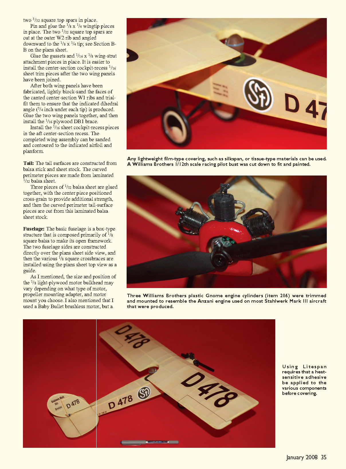
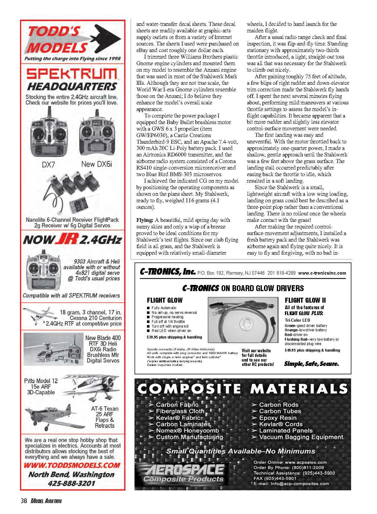
Any lightweight film-type covering, such as silkspan or tissue-type materials, can be used. I used buff-colored Litespan, a lightweight heat-shrinkable polyester tissue-type covering that closely resembles the natural linen used on many 1920s aircraft, including the Stahlwerk.
Using Litespan requires a heat-sensitive adhesive to be applied to components before covering. I used Coverite Balsarite, brushing the adhesive onto subassemblies wherever the covering needs to be heat-fastened. Once Balsarite has dried, apply the Litespan as with any heat-shrinkable covering; in overlap areas coat the joint with Balsarite.
The decals on my Stahlwerk were made using a home computer ink-jet printer and commercially available ink-jet and water-transfer decal sheets. These sheets are readily available from graphic-arts suppliers or internet sources. The sheets I used were purchased on eBay for roughly one dollar each.
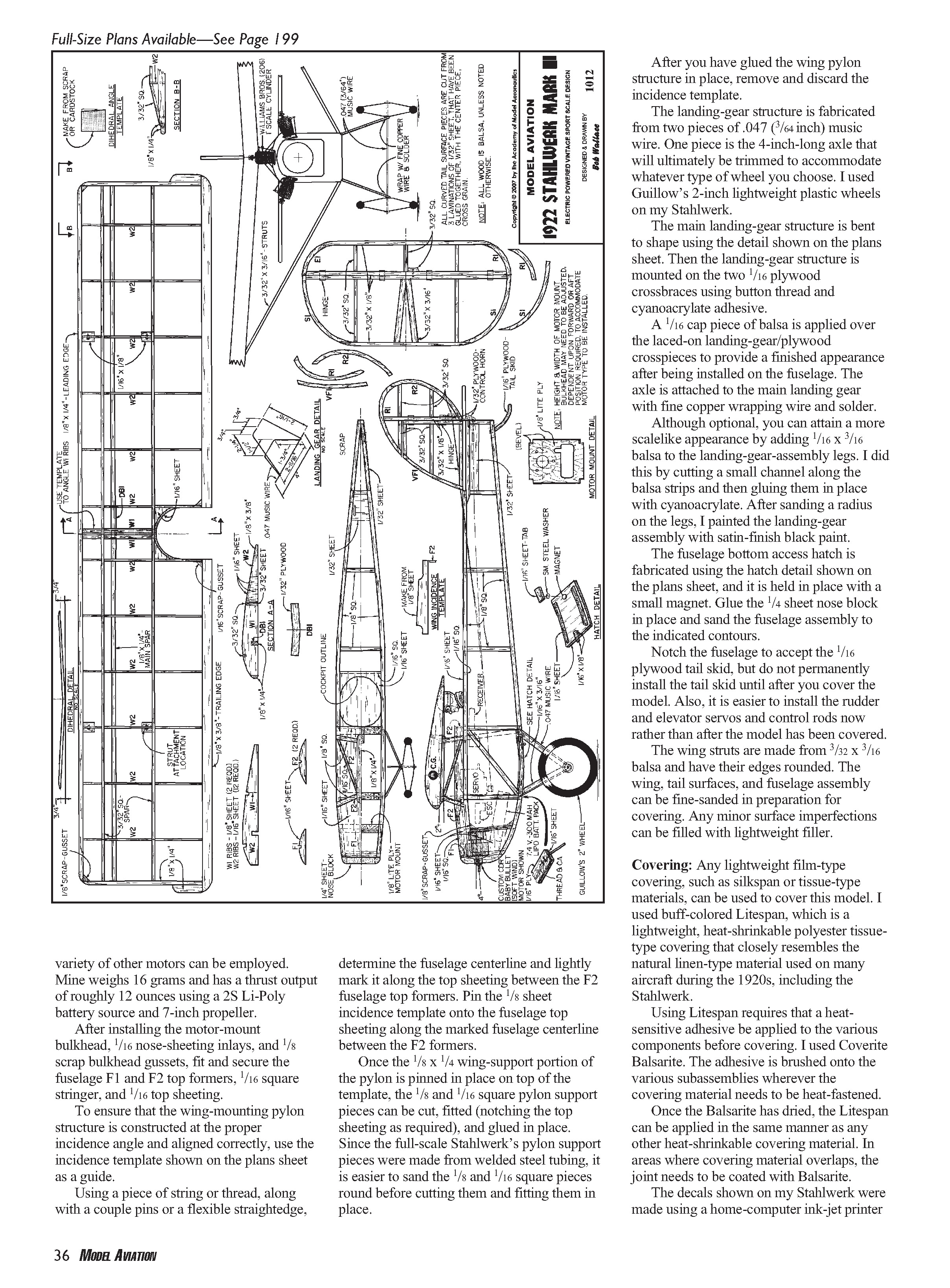
I trimmed three Williams Brothers plastic Gnome engine cylinders and mounted them to resemble the Anzani engine used in most Stahlwerk Mark IIIs. Though not true scale, the WW Gnome cylinders resemble the Anzani and enhance the model’s overall scale appearance.
Power package used:
- Baby Bullet Double Cool Wind brushless motor
- GWS 6 x 3 propeller (GW/EP6030)
- Castle Creations Thunderbird-9 ESC
- Apache 7.4 V, 300 mAh, 20C Li-Poly battery pack
Radio and servos:
- Airtronics RD6000 transmitter
- Corona RS410 single-conversion microreceiver
- Two Blue Bird BMS-303 microservos
I achieved the indicated center-of-gravity by positioning components as shown on the plans. My Stahlwerk, ready to fly, weighed 116 grams (4.1 ounces).
FLYING
A mild spring day with sunny skies and only a wisp of breeze provided ideal conditions for test flights. Since our club field is grass and the Stahlwerk has relatively small wheels, I hand-launched for the maiden flight.
After a radio range check and final inspection, a stationary, two-thirds-throttle toss was all that was necessary for a nice climb-out. After gaining roughly 75 feet, a few blips of right rudder and a down-elevator trim correction made the Stahlwerk fly hands-off. I performed mild maneuvers at various throttle settings to assess in-flight behavior and found that a bit more rudder and slightly less elevator travel were needed.
The first landing was easy and uneventful. With the motor throttled to about one-quarter power I made a shallow approach and eased to idle a few feet above the grass; the landing stall occurred predictably and resulted in a soft touchdown. Because the Stahlwerk is small and lightweight with low wing loading, grass landings are best described as a three-point plop rather than a conventional rollout—there is essentially no rollout once the wheels contact the grass.
After adjusting control-surface throws, I installed a fresh battery and flew again; the model was easy to fly and forgiving, with no bad in-flight characteristics. It has mild aerobatic capability suitable for this type of model. The Baby Bullet provided excellent power.
Subsequent flights lasted about 10–12 minutes using the Apache 2S 300 mAh Li-Poly pack. Recommended initial control-surface travel limits (each direction): 3/8 inch rudder and 1/4 inch elevator. These are starting points; builders may adjust them to suit flying preferences.
Although I have not yet flown my Stahlwerk indoors, I expect to when winter arrives in New England. Being slow-flying, docile, and easy to handle, it should be well suited for indoor flying.
The Stahlwerk is an easy-to-build sport-scale model that is a bit different. It is well suited to those who want to try traditional stick-and-tissue construction. Experienced modelers seeking a pleasant, nostalgic project should also find it a worthy subject.
If I can help answer questions about how I built my Stahlwerk, I will be glad to assist. Address: 91 Sylvan St., Avon CT 06001. Email: [email protected]
Bob Wallace
Sources
- Baby Bullet Double Cool Wind motor: CustomCDR, 1215 Diamondback Dr. NE, Albuquerque NM 87113 — www.customcdr.com
- Castle Creations Thunderbird-9 ESC: (913) 390-6939 — www.castlecreations.com
- Battery pack, servos, receiver, covering material: BP Hobbies, (732) 287-3933 — www.bphobbies.com
- Master Airscrew Balsa Stripper: (916) 631-8385 — www.masterairscrew.com
- Jim Jones Design (Jones) Balsa Stripper: A2Z CNC, (877) 754-7465 — www.a2zcnc.com/airplane.asp
Transcribed from original scans by AI. Minor OCR errors may remain.

