
A-20 Havoc
by Gary Fuller
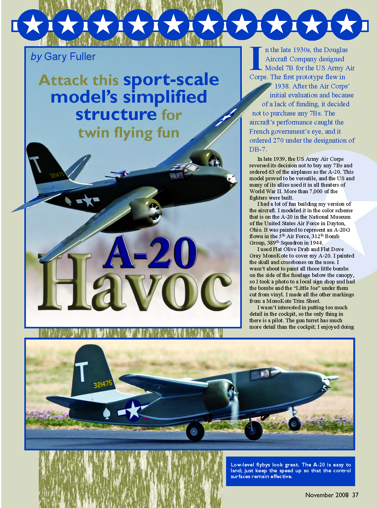
In the late 1930s, the Douglas Aircraft Company designed Model 7B for the US Army Air Corps. The first prototype flew in 1938. After the Air Corps' initial evaluation and because of a lack of funding, it decided not to purchase any 7Bs. The aircraft's performance caught the French government's eye, and it ordered 270 under the designation of DB-7.
In late 1939, the US Army Air Corps reversed its decision not to buy any 7Bs and ordered 63 of the airplanes as the A-20. This model proved to be versatile, and the US and many of its allies used it in all theaters of World War II. More than 7,000 of the fighters were built.
I had a lot of fun building my version of the aircraft. I modeled it in the color scheme that is on the A-20 in the National Museum of the United States Air Force in Dayton, Ohio. It was painted to represent an A-20G flown in the 5th Air Force, 312th Bomb Group, 389th Squadron in 1944.
I used Flat Olive Drab and Flat Dove Gray MonoKote to cover my A-20. I painted the skull and crossbones on the nose. I wasn't about to paint all those little bombs on the side of the fuselage below the canopy, so I took a photo to a local sign shop and had the bombs and the "Little Joe" under them cut from vinyl. I made all the other markings from a MonoKote Trim Sheet.
I wasn't interested in putting too much detail in the cockpit, so the only thing in there is a pilot. The gun turret has much more detail than the cockpit; I enjoyed doing it.
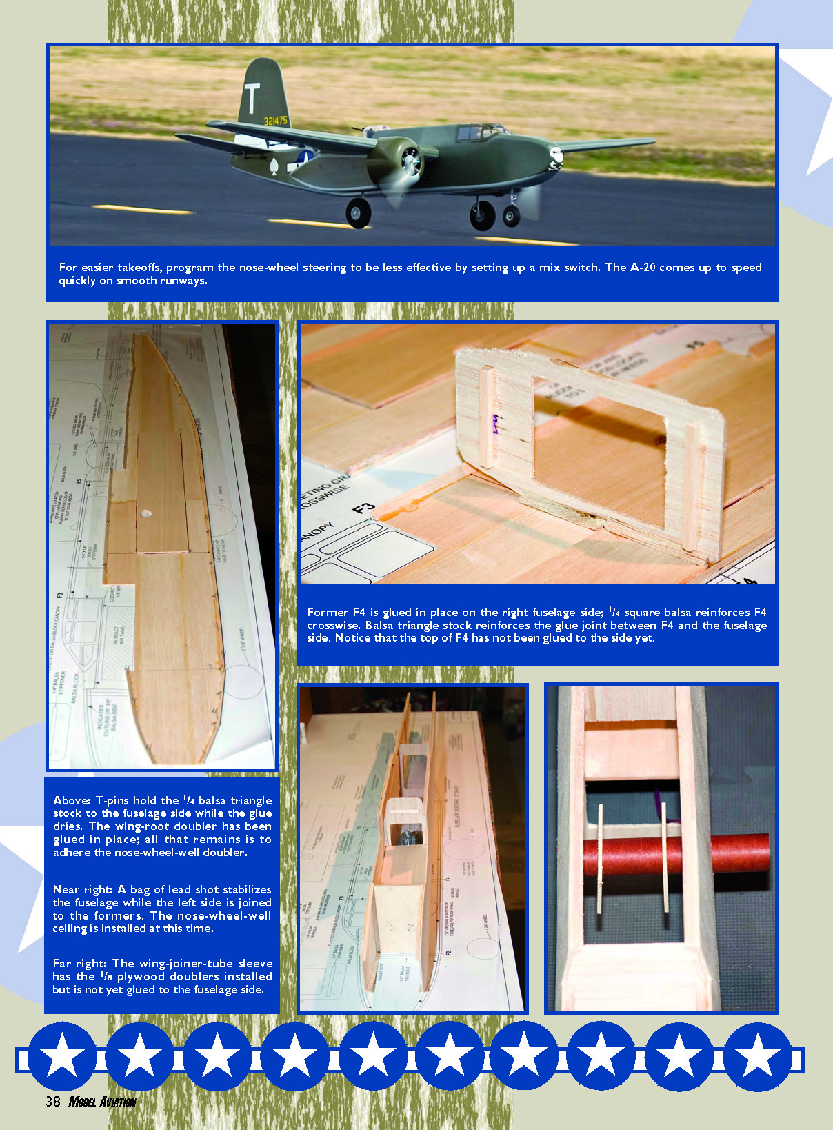
For easier takeoffs, program the nose-wheel steering to be less effective by setting up a mix switch. The A-20 comes up to speed quickly on smooth runways.
Former F4 is glued in place on the right fuselage side; 1/4 square balsa reinforces F4 crosswise. Balsa triangle stock reinforces the glue joint between F4 and the fuselage side. Notice that the top of F4 has not been glued to the side yet.
Above: T-pins hold the 1/4 balsa triangle stock to the fuselage side while the glue dries. The wing-root doubler has been glued in place; all that remains is to adhere the nose-wheel-well doubler.
Near right: A bag of lead shot stabilizes the fuselage while the left side is joined to the formers. The nose-wheel-well ceiling is installed at this time.
Far right: The wing-joiner-tube sleeve has the 1/8 plywood doublers installed but is not yet glued to the fuselage side.
A-20 Havoc
Gary Fuller
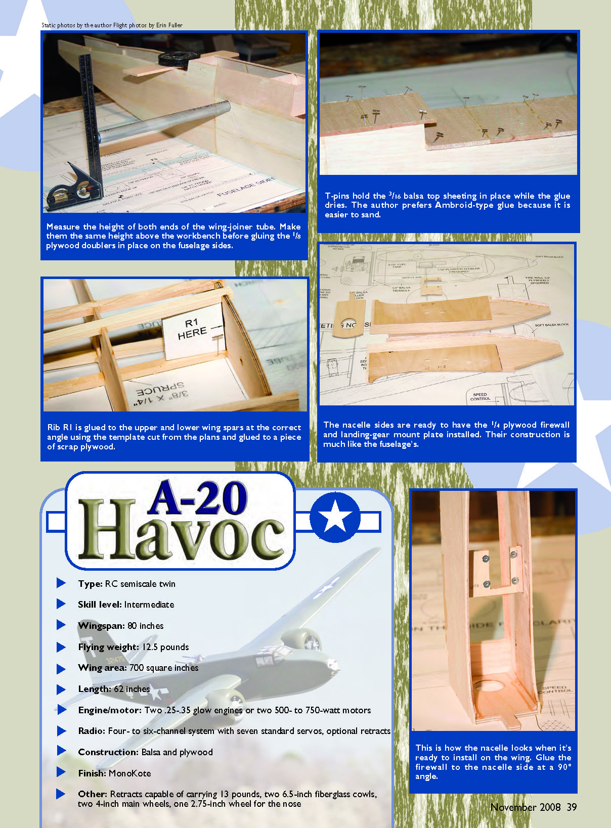
- Type: RC semiscale twin
- Skill level: Intermediate
- Wingspan: 80 inches
- Flying weight: 12.5 pounds
- Wing area: 700 square inches
- Length: 62 inches
- Engine/motor: Two .25-.35 glow engines or two 500- to 750-watt motors
- Radio: Four- to six-channel system with seven standard servos, optional retracts
- Construction: Balsa and plywood
- Finish: MonoKote
- Other: Retracts capable of carrying 13 pounds, two 6.5-inch fiberglass cowls, two 4-inch main wheels, one 2.75-inch wheel for the nose
Use an incidence meter to set the wing at the correct angle, and then push the wing into the fuselage side just enough so that the antirotation dowel and the 1/4-20 screw (with the head cut off) will mark the location of the mounting holes.
The custom fixture made from right-angle aluminum stock holds the motors aligned to each other while the nacelles are adhered to the wing.
Slide the 1/8 plywood doubler over the 1/4-20 wing-mounting screw, apply the glue to the doubler, and tighten the screw to hold the doubler in place.
As specified, 6-1/2-inch-diameter round cowls are available from Fiberglass Specialties. They are cut to length and then trimmed to fit using the template on the plans.
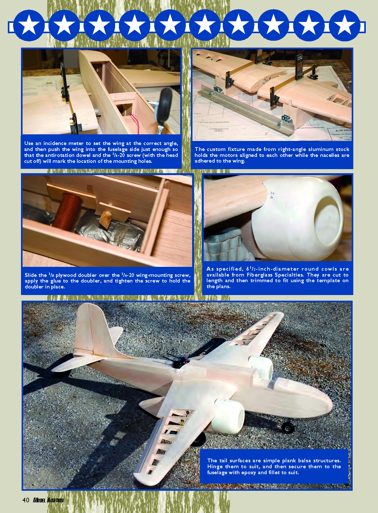
The tail surfaces are simple plank balsa structures. Hinge them to suit, and then secure them to the fuselage with epoxy and fillet to suit.
Transcribed from original scans by AI. Minor OCR errors may remain.

