
3D Hammer
By Dick Sarpolus
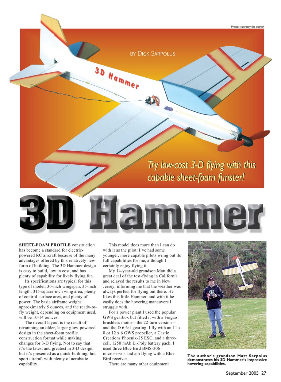
SHEET-FOAM PROFILE construction has become a standard for electric-powered RC aircraft because of the many advantages offered by this relatively new form of building. The 3D Hammer design is easy to build, low in cost, and has plenty of capability for lively flying fun.
Its specifications are typical for this type of model: 36-inch wingspan, 35-inch length, 315-square-inch wing area, plenty of control-surface area, and plenty of power. The basic airframe weighs approximately 5 ounces, and the ready-to-fly weight, depending on equipment used, will be 10-14 ounces.
The overall layout is the result of revamping an older, larger glow-powered design in the sheet-foam profile construction format while making changes for 3-D flying. Not to say that it's the latest and greatest in 3-D design, but it's presented as a quick-building, hot sport aircraft with plenty of aerobatic capability.
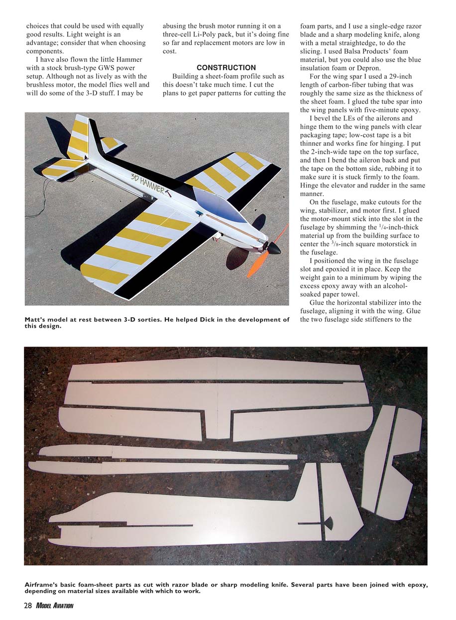
This model does more than I can do with it as the pilot. I've had some younger, more capable pilots wring out its full capabilities for me, although I certainly enjoy flying it.
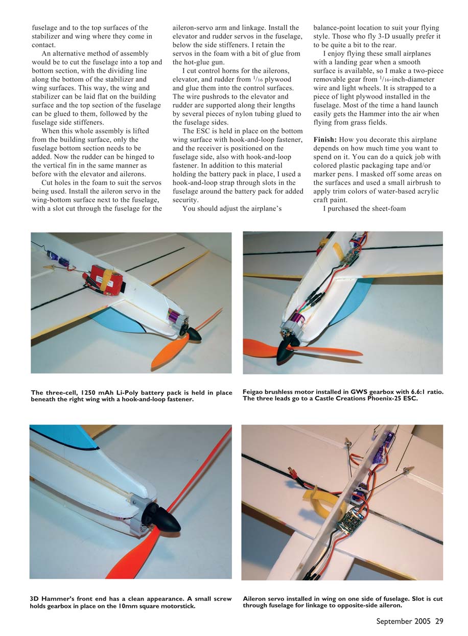
My 14-year-old grandson Matt did a great deal of the test-flying in California and relayed the results to me in New Jersey, informing me that the weather was always perfect for flying out there. He likes this little Hammer, and with it he easily does the hovering maneuvers I struggle with.
For a power plant I used the popular GWS gearbox but fitted it with a Feigao brushless motor—the 22-turn version—and the D 6.6:1 gearing. I fly with an 11 x 8 or 12 x 6 GWS propeller, a Castle Creations Phoenix-25 ESC, and a three-cell, 1250 mAh Li-Poly battery pack. I used three Blue Bird BMS-306 microservos and am flying with a Blue Bird receiver.
There are many other equipment choices that could be used with equally good results. Light weight is an advantage; consider that when choosing components.
I have also flown the little Hammer with a stock brush-type GWS power setup. Although not as lively as with the brushless motor, the model flies well and will do some of the 3-D stuff. I may be abusing the brush motor running it on a three-cell Li-Poly pack, but it's doing fine so far and replacement motors are low in cost.
CONSTRUCTION
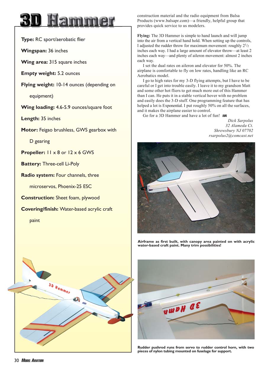
Building a sheet-foam profile such as this doesn't take much time. I cut the plans to get paper patterns for cutting the foam parts, and I use a single-edge razor blade and a sharp modeling knife, along with a metal straightedge, to do the slicing. I used Balsa Products' foam material, but you could also use the blue insulation foam or Depron.
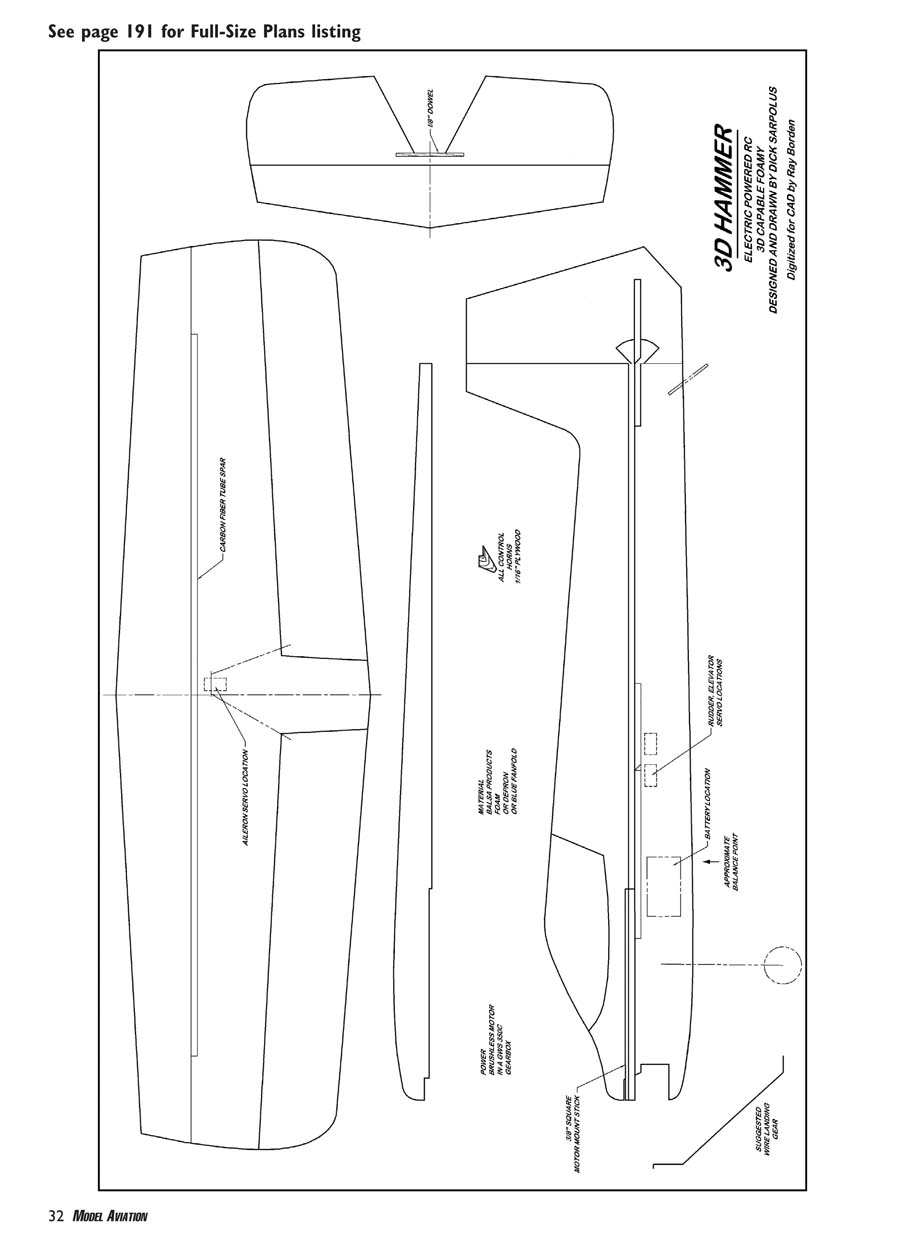
For the wing spar I used a 29-inch length of carbon-fiber tubing that was roughly the same size as the thickness of the sheet foam. I glued the tube spar into the wing panels with five-minute epoxy.
I bevel the LEs of the ailerons and hinge them to the wing panels with clear packaging tape; low-cost tape is a bit thinner and works fine for hinging. I put the 2-inch-wide tape on the top surface, and then I bend the aileron back and put the tape on the bottom side, rubbing it to make sure it is stuck firmly to the foam. Hinge the elevator and rudder in the same manner.
On the fuselage, make cutouts for the wing, stabilizer, and motor first. I glued the motor-mount stick into the slot in the fuselage by shimming the 1/4-inch-thick material up from the building surface to center the 3/8-inch square motorstick in the fuselage.
I positioned the wing in the fuselage slot and epoxied it in place. Keep the weight gain to a minimum by wiping the excess epoxy away with an alcohol-soaked paper towel.
Glue the horizontal stabilizer into the fuselage, aligning it with the wing. Glue the two fuselage side stiffeners to the fuselage and to the top surfaces of the stabilizer and wing where they come in contact.
An alternative method of assembly would be to cut the fuselage into a top and bottom section, with the dividing line along the bottom of the stabilizer and wing surfaces. This way, the wing and stabilizer can be laid flat on the building surface and the top section of the fuselage can be glued to them, followed by the fuselage side stiffeners.
When this whole assembly is lifted from the building surface, only the fuselage bottom section needs to be added. Now the rudder can be hinged to the vertical fin in the same manner as before with the elevator and ailerons.
Cut holes in the foam to suit the servos being used. Install the aileron servo in the wing-bottom surface next to the fuselage, with a slot cut through the fuselage for the aileron-servo arm and linkage. Install the elevator and rudder servos in the fuselage, below the side stiffeners. I retain the servos in the foam with a bit of glue from the hot-glue gun.
I cut control horns for the ailerons, elevator, and rudder from 1/16 plywood and glue them into the control surfaces. The wire pushrods to the elevator and rudder are supported along their lengths by several pieces of nylon tubing glued to the fuselage sides.
The ESC is held in place on the bottom wing surface with hook-and-loop fastener, and the receiver is positioned on the fuselage side, also with hook-and-loop fastener. In addition to this material holding the battery pack in place, I used a hook-and-loop strap through slots in the fuselage around the battery pack for added security.
You should adjust the airplane’s balance-point location to suit your flying style. Those who fly 3-D usually prefer it to be quite a bit to the rear.
I enjoy flying these small airplanes with a landing gear when a smooth surface is available, so I make a two-piece removable gear from 1/16-inch-diameter wire and light wheels. It is strapped to a piece of light plywood installed in the fuselage. Most of the time a hand launch easily gets the Hammer into the air when flying from grass fields.
Finish: How you decorate this airplane depends on how much time you want to spend on it. You can do a quick job with colored plastic packaging tape and/or marker pens. I masked off some areas on the surfaces and used a small airbrush to apply trim colors of water-based acrylic craft paint.
I purchased the sheet-foam construction material and the radio equipment from Balsa Products (www.balsapr.com)—a friendly, helpful group that provides quick service to us modelers.
Flying: The 3D Hammer is simple to hand launch and will jump into the air from a vertical hand hold. When setting up the controls, I adjusted the rudder throw for maximum movement; roughly 2½ inches each way. I had a large amount of elevator throw—at least 2 inches each way—and plenty of aileron movement; almost 2 inches each way.
I set the dual rates on aileron and elevator for 50%. The airplane is comfortable to fly on low rates, handling like an RC Aerobatics model.
I go to high rates for my 3-D flying attempts, but I have to be careful or I get into trouble easily. I leave it to my grandson Matt and some other hot fliers to get much more out of this Hammer than I can. He puts it in a stable vertical hover with no problem and easily does the 3-D stuff. One programming feature that has helped a lot is Exponential. I put roughly 50% on all the surfaces, and it makes the airplane easier to control.
Go for a 3D Hammer and have a lot of fun! MA
Dick Sarpolus 32 Alameda Ct. Shrewsbury NJ 07702 [email protected]
3D Hammer
3D HAMMER ELECTRIC POWERED R/C DESIGNED AND DRAWN BY DICK SARPOLUS Digitized for CAD by Ray Bordon
Transcribed from original scans by AI. Minor OCR errors may remain.

