
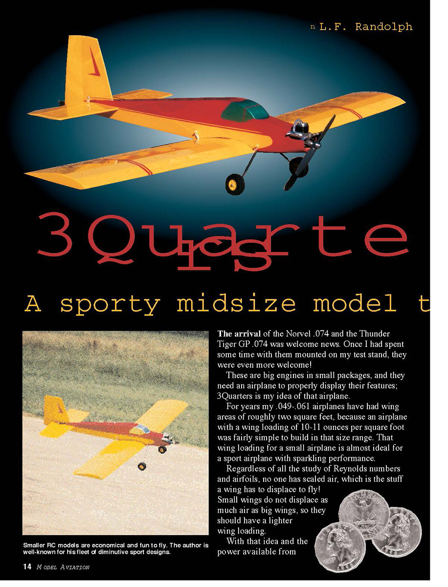
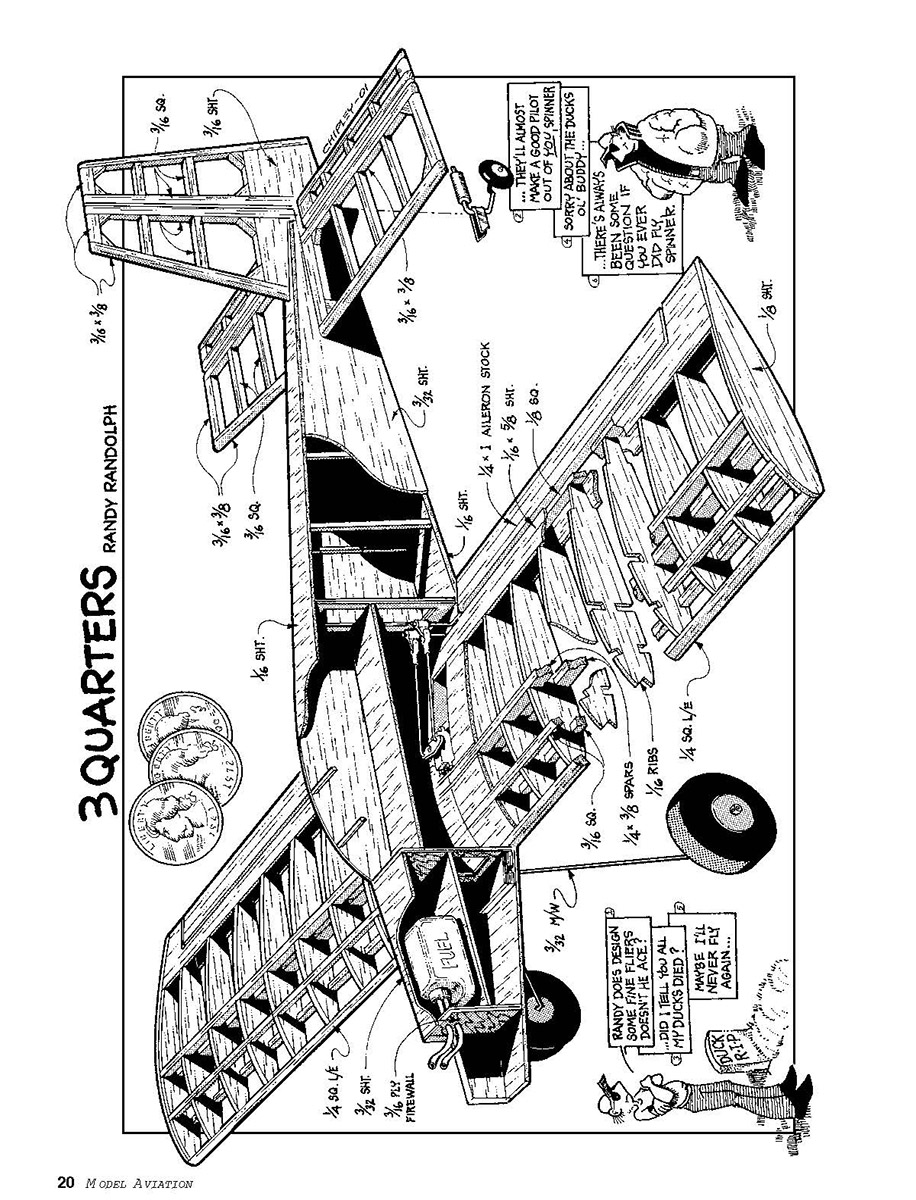
3Quarters
A sporty midsize model
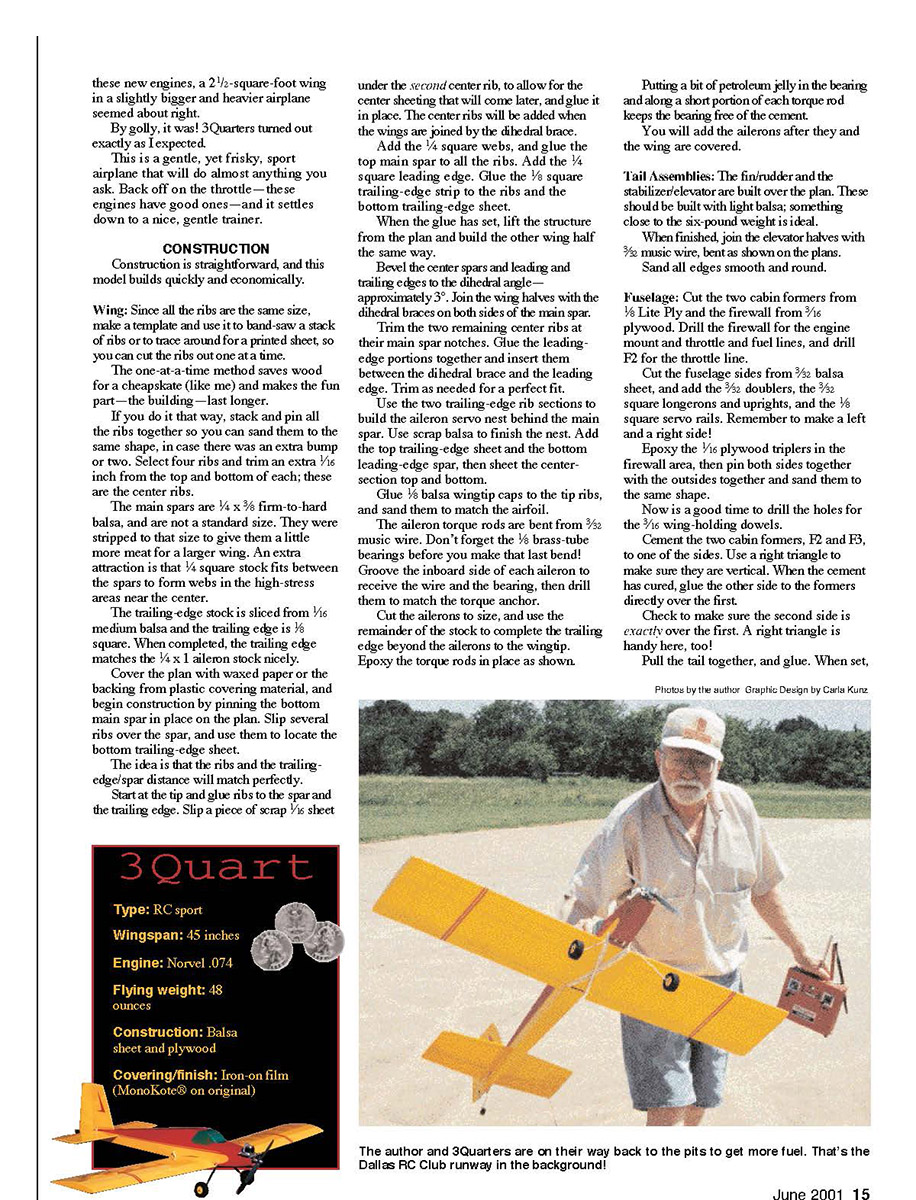
The arrival of the Norvel .074 and the Thunder Tiger GP .074 was welcome news. Once I had spent some time with them mounted on my test stand, they were even more welcome!
These are big engines in small packages, and they need an airplane to properly display their features; 3Quarters is my idea of that airplane.
For years my .049–.061 airplanes have had wing areas of roughly two square feet, because an airplane with a wing loading of 10–11 ounces per square foot was fairly simple to build in that size range. That wing loading for a small airplane is almost ideal for a sport airplane with sparkling performance.
Regardless of all the study of Reynolds numbers and airfoils, no one has scaled air, which is the stuff a wing has to displace to fly!
Small wings do not displace as much air as big wings, so they should have a lighter wing loading.
With that idea and the power available from these new engines, a 2-1/2-square-foot wing in a slightly bigger and heavier airplane seemed about right. By golly, it was! 3Quarters turned out exactly as I expected. This is a gentle, yet frisky, sport airplane that will do almost anything you ask. Back off on the throttle—the engines have good ones—and it settles down to a nice, gentle trainer.
Construction is straightforward, and this model builds quickly and economically.
Construction
Wing
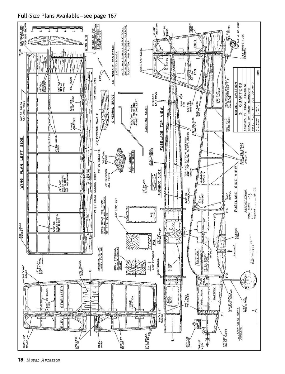
- Since all the ribs are the same size, make a template and use it to band-saw a stack of ribs or to trace around for a printed sheet so you can cut the ribs out one at a time. The one-at-a-time method saves wood for a cheapskate (like me) and makes the fun part—the building—last longer. If you do it that way, stack and pin all the ribs together so you can sand them to the same shape, in case there was an extra bump or two.
- Select four ribs and trim an extra 1/16 inch from the top and bottom of each; these are the center ribs.
- The main spars are 1/4 x 3/8 firm-to-hard balsa, and are not a standard size. They were stripped to that size to give them a little more meat for a larger wing. An extra attraction is that 1/4 square stock fits between the spars to form webs in the high-stress areas near the center.
- The trailing-edge stock is sliced from 1/16 medium balsa and the trailing edge is 1/8 square. When completed, the trailing edge matches the 1/4 x 1 aileron stock nicely.
Cover the plan with waxed paper or the backing from plastic covering material, and begin construction by pinning the bottom main spar in place on the plan. Slip several ribs over the spar, and use them to locate the bottom trailing-edge sheet. The idea is that the ribs and trailing-edge/spar distance will match perfectly. Start at the tip and glue ribs to the spar and the trailing edge.
Slip a piece of scrap 1/16 sheet under the second center rib to allow for the center sheeting that will come later, and glue it in place. The center ribs will be added when the wings are joined by the dihedral brace. Add the 1/4 square webs, and glue the top main spar to all the ribs. Add the 1/4 square leading edge. Glue the 1/8 square trailing-edge strip to the ribs and the bottom trailing-edge sheet. When the glue has set, lift the structure from the plan and build the other wing half the same way.
Bevel the center spars and leading and trailing edges to the dihedral angle—approximately 3°. Join the wing halves with the dihedral braces on both sides of the main spar. Trim the two remaining center ribs at their main spar notches. Glue the leading-edge portions together and insert them between the dihedral brace and the leading edge. Trim as needed for a perfect fit.
Use the two remaining trailing-edge rib sections to build the aileron servo nest behind the main spar. Use scrap balsa to finish the nest. Add the top trailing-edge sheet and the bottom trailing-edge spar, then sheet the center section top and bottom. Glue 1/8 balsa wingtip caps to the tip ribs, and sand them to match the airfoil.
The aileron torque rods are bent from 3/32-inch music wire. Don't forget the 1/8 brass-tube bearings before you make that last bend! Groove the inboard side of each aileron to receive the wire and the bearing, then drill them to match the torque-anchor.
Cut the ailerons to size, and use the remainder of the stock to complete the trailing edge beyond the ailerons to the wingtip. Epoxy the torque rods in place as shown. Putting a bit of petroleum jelly in the bearing and along a short portion of each torque rod keeps the bearing free of the cement.
You will add the ailerons after they and the wing are covered.
Tail assemblies
- The fin/rudder and the stabilizer/elevator are built over the plan. These should be built with light balsa; something close to the six-pound weight is ideal.
- When finished, join the elevator halves with 3/32 music wire, bent as shown on the plans.
- Sand all edges smooth and round.
Fuselage
- Cut the two cabin formers from 1/8 Lite Ply and the firewall from 3/16 plywood. Drill the firewall for the engine mount and throttle and fuel lines, and drill F2 for the throttle line.
- Cut the fuselage sides from 3/32 balsa sheet, and add the 3/32 doublers, the 3/32 square longerons and uprights, and the 1/8 square servo rails. Remember to make a left and a right side!
- Epoxy the 1/16 plywood tripler in the firewall area, then pin both sides together with the outsides together and sand them to the same shape.
- Drill the holes for the 3/16 wing-holding dowels.
- Cement the two cabin formers, F2 and F3, to one of the sides. Use a right triangle to make sure they are vertical. When the cement has cured, glue the other side to the formers directly over the first. Check to make sure the second side is exactly over the first.
- Pull the tail together, and glue. When set, sand and shape. Epoxy the firewall in place. There is no sidethrust or downthrust in the engine, so the firewall should be perpendicular to the thrustline in both airplanes.
- Build up the landing-gear mount as shown on the plans, and glue it in place just in front of the wing. Sheet the top of the fuselage from the front of the cabin aft.
- Glue the tank bottom in place, and mount the tank; hold it in place with foam blocks.
- Bring the fuel lines out through the firewall, and install the inner Nyrod for the throttle line. Route the line around the tank on the proper side to suit your engine.
If you are going to use the .047 music-wire pushrods as shown on the plans, temporarily mount the servos in the cabin area and trace a line from them to the rudder and elevator horns. Make a 1/8-inch hole in the top sheeting where they would exit the fuselage.
Make and install the pushrod guide in the proper location. Check to see if the pushrods fit smoothly through the bearing and exit holes. You can use Nylros instead of the wire; if you do, install them at this time.
When this installation is complete, finish sheeting the bottom and top of the fuselage.
Notice the 1/16 plywood tail-wheel mount. Use the fin as a guide and cut its slot into the top fuselage sheet as shown on the plans, then sand the completed fuselage.
Finishing
- Cover the tail surfaces separately, hinge them, and add the control horns while they are still easy to handle. Plastic control horns are shown on the plan, but 1/16 aircraft plywood horns are recommended for many builders.
- Notch the surface to fit the horn, epoxy it through the surface, and sand flush on the other side.
- MonoKote® was used for the covering material and for the hinges in the original build.
- It is much easier to cover the fuselage without the encumbrance of the tail surfaces—cover the fuselage first, then fit the tail surfaces.
- Trim the covering from the stabilizer and fin slots, fit the surfaces in their respective openings, mark them, and remove the covering that will come in contact with the fuselage slots.
- Slip the parts into place, and be sure that the stabilizer is horizontal and the fin is vertical before gluing them to the fuselage.
- Remove the covering from the holes drilled for the dowels that hold the wing, and glue.
- Cover the wings, and after covering the ailerons, trim the covering from the groove that was cut to clear the torque rods. Epoxy the torque-rod anchors into the ailerons as you hinge them to the wing.
Torque-rod arm links can be formed from tin-can stock, drilled, and soldered to the tops of the arms. The measurements shown on the plan will give the proper aileron deflection when the pushrods are connected 3/8 inch from the center of the aileron servo arm.
Bend up the landing gear—one right and one left—and use soldered washers or wheel collars to hold the two-inch wheels on the axles. The gear legs are held in their mount with metal straps and #2 wood screws.
Build up the tail-wheel mount from 1/8 plywood with 1/32 plywood doublers in the stress areas, and drill it for a 3/32 brass-tubing bearing. The tail-wheel axle and steering arm is bent from 1/16 music wire, and the 3/4-inch tail wheel is captured by soldered washers. A commercial tail wheel and mount will work fine if it is not too heavy.
It is convenient to make 1/8 plywood trays to mount the servos—a small one for the aileron servo and one for the throttle, elevator, and rudder servos. Mount the aileron servo and connect the ailerons, and run the pushrods from the cabin to the tail surfaces.
Mount the engine, slip the battery under the tank and the receiver in the location indicated. Slide the three servos in their mount back and forth until you find the place that allows the airplane to balance on the main spar when the wing is mounted. Glue the servos to the servo rail in that location.
Mount the engine and connect the fuel lines. Connect the elevator, rudder, and throttle servos to their respective control surfaces, and the airplane is complete.
Control-surface throw seems to be a problem with scratchbuilders, and the solution is quite simple: a deflection of 20–25° both ways should be right in nearly all cases. If that is not enough, change the design rather than the throw!
Before the first flight, check the balance once more and be certain that the surfaces move in the proper direction when the control is given. Even though modern equipment is very reliable, it is a good idea to give a new airplane a collapsed-antenna distance test.
Flying
- Ground-tracking is very good, and only a slight amount of right rudder is needed to keep the model straight. It should take off from the three-point position, but a little down-elevator to lift the tail makes the takeoff look better.
- Unless there are some bad warps, straight-and-level flight should be well within the limits of the transmitter trim tabs. If that is not the case, land and correct the problem on the ground.
- This is a gentle airplane with aerobatic capabilities that include loops, rolls, stall turns, snap rolls, spins, or any combination of the above. Most maneuvers can be performed inverted as well as upright.
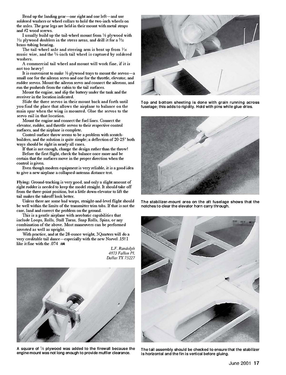
With practice, and at the 28-ounce weight, 3Quarters will do a very creditable tail dance—especially with the new Norvel .15! I like it fine with the .074.
L.F. Randolph 4873 Fallon Pl. Dallas TX 75227
Note: The scanned page included the full-size plan/illustration (dimensional callouts and detail labels) but no additional continuous article text beyond what is transcribed above. If you would like, I can transcribe the drawing labels and dimensions from the plan or produce a single combined file of article copy plus plan labels. Which would you prefer?
Transcribed from original scans by AI. Minor OCR errors may remain.

