
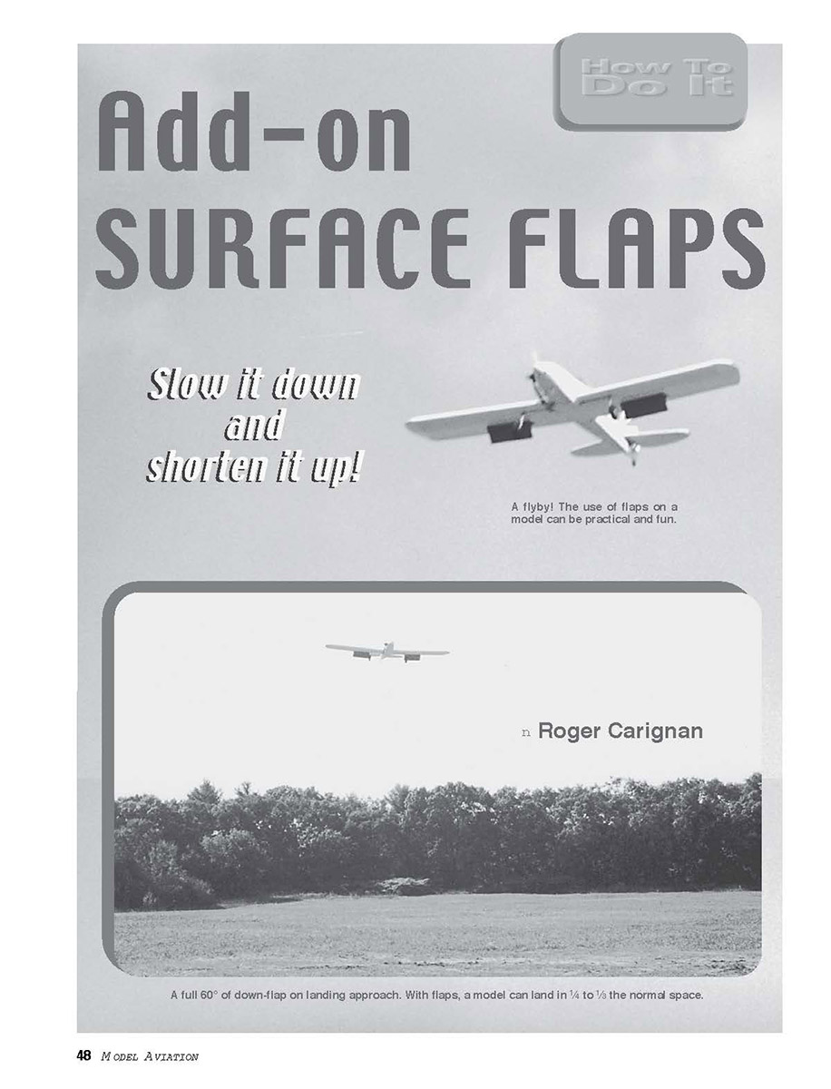
Add-on Surface Flaps
Slow it down and shorten it up!
by Roger Carignan
Some models—especially larger ones—are difficult to land on short runways because of their low drag and tendency to keep flying when you want them to settle in. Combine this with the inability to make long approaches because of field tree-line limitations and no headwind, and you have a handful.
I experienced this with my Super Sportster 90/120. This model has full strip ailerons. I tried using flaperons, but they were ineffective. I also tried various landing approaches that several experienced fliers suggested, but the results were inconsistent.
At first, adding flaps to the already built wing seemed to be too much work without almost building a new wing. This was complicated because of the strip ailerons; adding conventional flaps would require changing from strip ailerons to outer wing ailerons, and making all the control-linkage changes.
An easier method of adding lift and drag was needed.
The solution was to make part of the lower wing surface into a flap, with a forward hinge that would deploy into the airstream and add lift and drag. I had not seen this kind of flap used in models or in general aviation.
Some have said this is a type of "split" flap, but all the ones I have seen are located at the trailing edge of the wing and could not be implemented easily because of the strip ailerons.
These underwing surface flaps require no change to the strip ailerons or control linkages, and can be relatively easy to install.
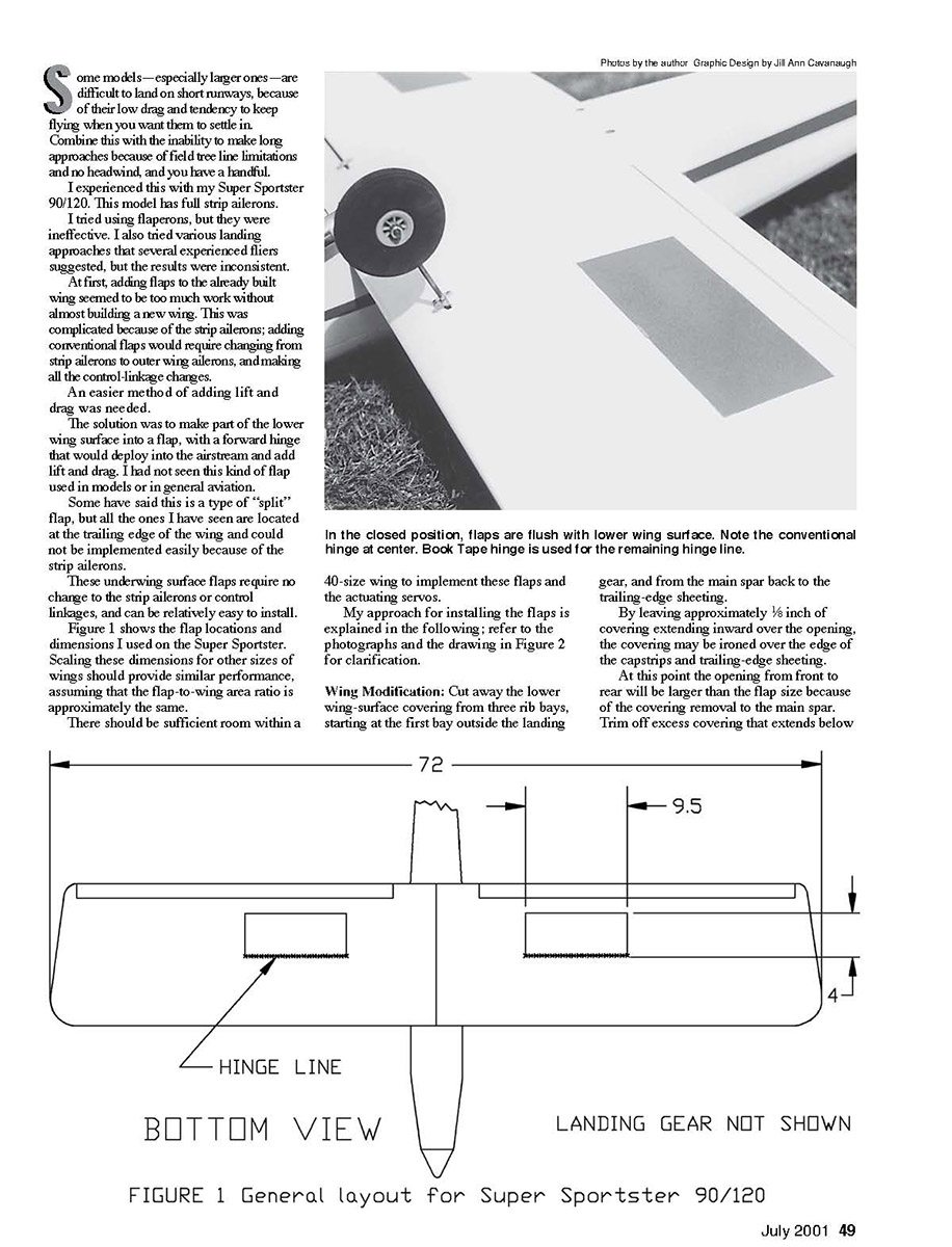
Figure 1 shows the flap locations and dimensions I used on the Super Sportster. Scaling these dimensions for other sizes of wings should provide similar performance, assuming that the flap-to-wing area ratio is approximately the same.
There should be sufficient room within a 40-size wing to implement these flaps and the actuating servos.
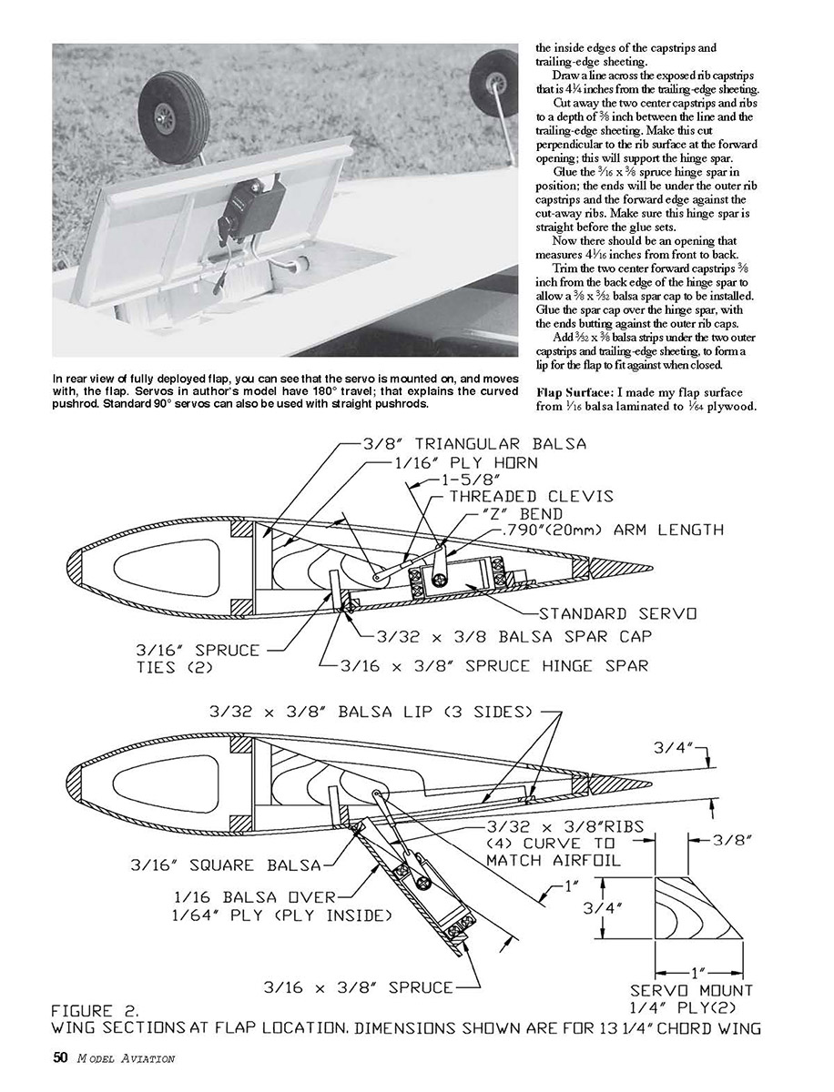
My approach for installing the flaps is explained below; refer to the photographs and the drawing in Figure 2 for clarification.
Wing Modification
- Cut away the lower wing-surface covering from three rib bays, starting at the first bay outside the landing gear, and from the main spar back to the trailing-edge sheeting.
- Leave approximately 1/8 inch of covering extending inward over the opening so the covering may be ironed over the edge of the capstrips and trailing-edge sheeting.
- At this point the opening from front to rear will be larger than the flap size because of the covering removal to the main spar. Trim off excess covering that extends below the inside edges of the capstrips and trailing-edge sheeting.
- Draw a line across the exposed rib capstrips that is 4 1/4 inches from the trailing-edge sheeting. Cut away the two center capstrips and ribs to a depth of 3/8 inch between the line and the trailing-edge sheeting. Make this cut perpendicular to the rib surface at the forward opening; this will support the hinge spar.
- Glue the 3/16 x 3/8-inch spruce hinge spar in position; the ends will be under the outer rib capstrips and the forward edge against the cut-away ribs. Make sure this hinge spar is straight before the glue sets.
- Now there should be an opening that measures 4 1/4 inches from front to back.
- Trim the two center forward capstrips 3/8 inch from the back edge of the hinge spar to allow a 3/8 x 3/32-inch balsa spar cap to be installed. Glue the spar cap over the hinge spar, with the ends butting against the outer rib caps.
- Add 3/32 x 3/8-inch balsa strips under the two outer capstrips and trailing-edge sheeting to form a lip for the flap to fit against when closed.
Flap Surface
- I made my flap surface from 1/16-inch balsa laminated to 1/4-inch plywood. It would probably work as well using 3/32-inch balsa or 1/16-inch plywood.
- Cut each piece to leave a 5/32-inch space around the edges when fitted into the wing’s flap opening.
- Form a stiffening framework for the flap, as shown in the drawing. The 3/32-inch ribs are made with a curved side to match the original airfoil shape in the flap area.
- Glue balsa strip forms to the flap’s hinge line. This piece is glued flush with the flap forward edge. Space the other flap-frame components so there will be clearance from the wing stop lip when the flaps are fully retracted.
- The center ribs are positioned with the same spacing as the wing ribs. The fairly heavy 3/16 x 3/8-inch spruce trailing-edge piece provides the required flap stiffness under full air-load conditions.
- Cover the flap with film covering. I used a red covering against a white wing so the flaps would show in photographs. Recover the open area between the wing spars and the flap hinge line.
Servo Installation
This may seem strange at first, but the servos are mounted on and move with the flaps. This simplifies the linkage and provides positive flap control.
- If you can get one servo that has reversed travel, the servo installation can be made symmetrical (both servos have the same orientation relative to the aircraft centerline). This can be done by either changing the internal servo wiring or using a reversing adapter. Another possibility—if you have a computer radio with channel-mixing capability—is to program each servo with a mix from the flap-control channel.
- If none of the above is possible, the servos can be mounted asymmetrically to obtain synchronized operation. This will introduce a slight imbalance that may need to be corrected with a small trim on one wingtip.
- Drill the servo screw pilot holes in the 1/8-inch plywood servo mount. Glue the servo mounts so that the servos bear against one or the other flap center ribs and with the rear mounts against the rear spar or stiffener.
- With the servos mounted in each flap, locate the inner horn so it will have proper alignment with the threaded clevis and Z-bend pushrod located at the outside of the servo arm.
- Reinforce the inner horn with spruce tie glued to each side and to the hinge spar.
- Carefully mark the inner horn hole location per the drawing dimensions, and drill the clevis pin hole. The servo arm length must be as specified in the drawing to achieve a full flap deflection of 60°.
- Route servo leads through the inner ribs and into a decentering bay, where they connect to a Y connector. I made holes through the ribs using a tubing with teeth filed into the end. Then the holes were lined with 1/8-inch heat-shrink tubing.
Hinge Details
- I used a single conventional control-surface hinge centered on the flap hinge line, and 3M Scotch Duct Tape for the remaining hinge line.
- This provided the strength required to support the servo-actuation forces and the sealing of the hinge line.
Adjustment
- With both servos connected to the receiver flap channel, set the transmitter flap channel to its down-flap position. Initially set the transmitter flap endpoint setting to its normal value.
- Mount the servo arm to each servo so that it points directly to the inner horn hole. If the servos are not the same, average them using the transmitter endpoint adjustment. A small amount of misalignment will be noncritical.
- Adjust the clevis length to achieve a 60° deflection of the flap in the down position. Slowly move the flap control to the closed position until the flaps just close in the flush position.
- If the flaps close before the transmitter end travel is reached, change the end-travel position so the flaps just close.
- If one flap closes before the other, shorten the clevis on the flap that needs more closure. This causes a slight difference in the down-flap position. This is rarely severe and will not cause a problem. If it is a problem, it is because the servos are not of equal travel. Try to select servos with better-matched travel or modify the length of the servo arm to achieve equal travel.
- It is important that the servos are not trying to cause a tighter closure when the flaps are in the fully retracted position, thereby drawing current. Listen for servo buzz when the flaps are in the fully retracted position; if it's heard, readjust the transmitter end travel and/or the clevis length.
- A better method is to have an ammeter that can be temporarily inserted to monitor receiver-battery current until the current does not increase and remains steady when the flaps are fully closed.
Flying
My reaction to the first flight with the flaps was “Wow, what a difference!” The results exceeded all my expectations.
The model with flaps down is a completely different aircraft. Now it can make steep approaches with a glide after clearing the tree line without gaining speed and overshooting the runway.
As with any flap deployment, slow the model first and slowly lower the flaps; there will be some ballooning that can be corrected with down-elevator. Once speed is stabilized, the model is nearly flying much slower with no change in elevator trim required.
Good aileron control is still very effective throughout the flap-down approach, and there is no tendency for tip-stalling—even in tight turns. Rudder control seems to be less effective with flaps down, but adequate.
The flaps’ performance remained unchanged.
Sometimes I enjoy just flying around with full flaps to demonstrate “slow flight”—very uncharacteristic for this type of model, and a lot of fun.
Transcribed from original scans by AI. Minor OCR errors may remain.

