

Aerobatic P-47 Thunderbolt - 2006/07
by Bill Werwage
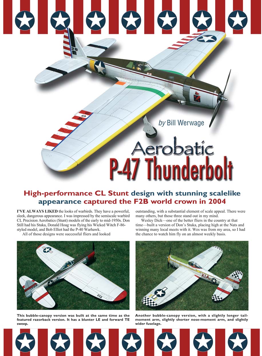
High-performance CL Stunt design with stunning scalelike appearance captured the F2B world crown in 2004
I've always liked the looks of warbirds. They have a powerful, sleek, dangerous appearance. I was impressed by the semiscale warbird CL Precision Aerobatics (Stunt) models of the early to mid-1950s. Don Still had his Stuka, Donald Hoag was flying his Wicked Witch F-86-styled model, and Bob Elliot had the P-40 Warhawk.
All of those designs were successful fliers and looked outstanding, with a substantial element of scale appeal. There were many others, but those three stand out in my mind.
Wesley Dick—one of the better fliers in the country at that time—built a version of Don’s Stuka, placing high at the Nats and winning many local meets with it. Wes was from my area, so I had the chance to watch him fly on an almost weekly basis. He was an inspiration to me because of the quality and consistency of his flying performances, but I also was impressed by his model’s aesthetics. The scale aspect of that Stuka seemed to add measurably to the appeal.
At that time I was learning the fine points of I-beam wing construction and flying the Detroiter-style airplanes. I was obsessed with these models’ sleek overall appearance. Although I liked the scale looks of the airplanes I have mentioned, I was not ready to give up on the direction in which I was headed with the I-beam models. I knew I wanted to build some semiscale Stunt models, but that would have to wait awhile. And it turned out to be quite awhile!
Years later, at the 1968 Nats in Olathe, Kansas, those present got a glimpse of just how far the scale envelope in Stunt would eventually be pushed. Al Rabe showed up with a scale-looking P-51 Mustang. The P-51’s fuselage was wider and more scalelike than on any previous semiscale Stunt models. It featured dihedral, a smaller-than-usual stabilizer and elevator assembly, almost-scale landing-gear length, and it flew quite well. That interest I had in scale a few years earlier was reawakened.
At that time I was in the process of developing a new design that eventually became the USA-1, so, again, my urges had to wait. During the time I was successfully competing with the USA-1, Al Rabe continued his development of the scale Stunt model. After the initial Mustang in 1968 he produced the first of several Bearcat designs, which was built using the normal sheet and hollowed block-type fuselage construction. It flew well; he captured second place at the 1969 Nats with it.
The next year Al showed up at the Nats with an even more advanced version of the Bearcat. It featured a molded-balsa fuselage and numerous other molded parts. It had working shock-absorbing landing gear and his now-famous movable rudder. Al placed second again, proving that the scale Stunt model was a viable weapon that the judges would take seriously.
During this period I was fortunate enough for Al to ask me to try his models. While impressed, I was not ready to trade the USA-1 for a scale Stunt aircraft for competition. However, I did build a semiscale Guardian featuring all of Al's developments to obtain a benchmark. When spring arrived it stayed on the bench, where it remains today and has left a mark.
My development of the USA-1's aerodynamics evolved into the Junar and the Geo-XL series. I was beginning to build a fairly large stable of great-flying airplanes and felt that it was finally time to give scale Stunt a serious try.
The Design Process Of all the scale warbirds I have admired throughout the years, the P-47 Thunderbolt is one of my favorites. It has perhaps the most powerful look of all the famous World War II fighters. It is also a subject that had not been modeled frequently. Charles Parrott designed a number of semiscale Stunt models in the 1960s, and among them was a P-47.
In 1994 I began drawing my first Thunderbolt. I decided to use I-beam construction in a wing that featured airfoils similar to those of my Super Ares. The airfoils were also similar to those Randy Smith used in his SV series of Stunt designs. I went to a slightly higher aspect ratio and used full-span flaps.
The actual I-beam in that first model was made from balsa and carbon. Paul Walker supplied me with the materials for it that were essentially the same as those he used in his I-beam Impact design.
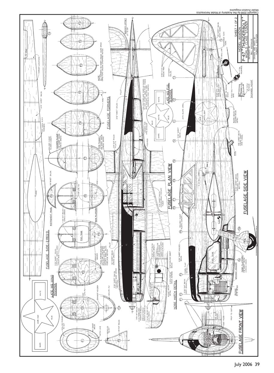
The construction of this Thunderbolt marked the beginning of my using molded shells for the fuselage shapes. I used a minimal fuselage crutch to hold the wing and tail assembly in alignment and added full-form molded top and bottom shells to get the desired shapes. At first the mass of this fuselage concerned me; I wasn't used to such a huge appearance. My fears proved to be unfounded, however, and future Thunderbolt fuselages grew even larger and wider.
I have heard that there is some sort of aerodynamic principle for the aspect ratio of a drop tank. The 6:1 ratio (length versus width) is said to go through the air with the least amount of drag. The thin fuselages commonly used in classic Stunt-model design may not be ideal.
Each successive Thunderbolt I have built has had a wider, deeper fuselage and has come closer to the 6:1 principle. I have noticed no discernible loss of performance because of this, and these models may be among the most stable in turbulence and wind I have had. The molded fuselage is certainly more torsionally rigid, and that is always good. The stability may simply be a by-product of the extreme rigidity. At any rate, the larger fuselage hasn't hurt!
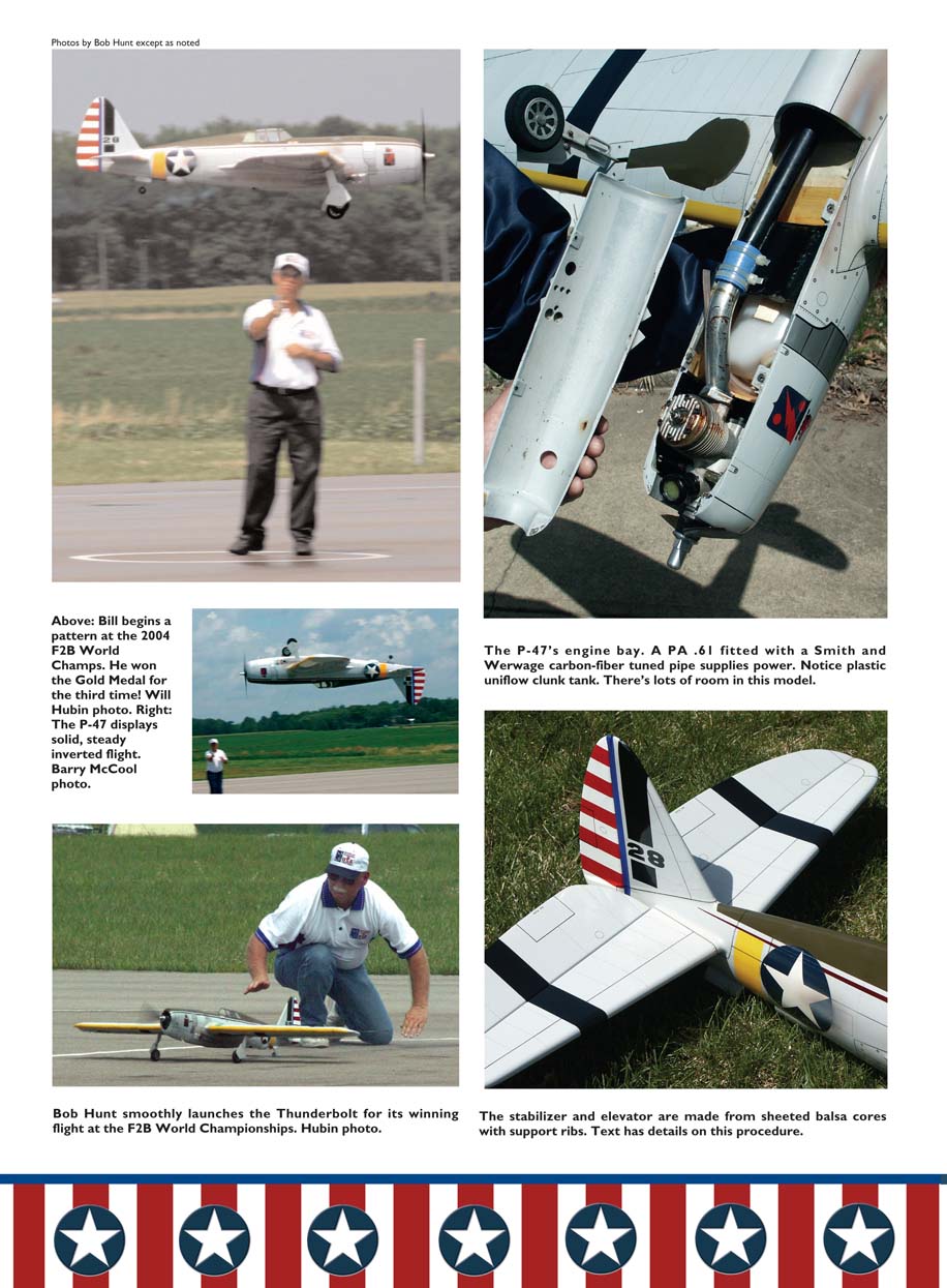
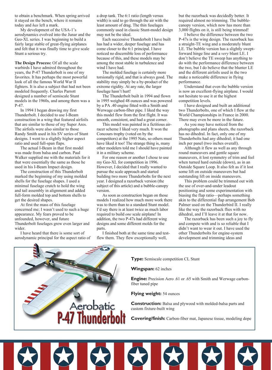
The Thunderbolt built in 1994 and flown in 1995 weighed 48 ounces and was powered by a PA .40 engine fitted with a Smith and Werwage carbon-fiber pipe. I liked the way this model flew from the first flight. It was smooth, consistent, and had a great corner.
This model was painted in a fictitious air-racer scheme I liked very much. It won the Concours trophy (voted on by the competitors) at the 1995 Nats, so others must have liked it too! The strange thing is, many other modelers told me I should have painted it in a military scheme.
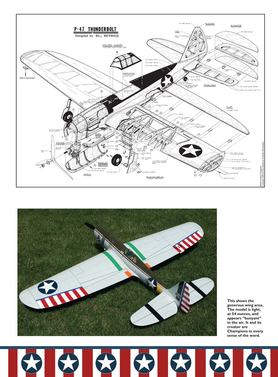
For one reason or another I chose to use my Geo-XL for competition in 1996. However, I decided that I really wanted to pursue the scale approach and started building two more Thunderbolts for the next year. I designed a razorback version (the subject of this article) and a bubble-canopy version.
As soon as construction began on those models I realized how much more work there was to them than to a standard Stunt model. I'd say there is at least twice as much labor required to build one scale airplane! In addition, the two P-47s had different wing designs and some different molds for the parts.
I finished both at the same time and test-flew them. They flew exceptionally well, but the razorback was decidedly better. It required almost no trimming. The bubble-canopy version, which now has no more than 3,000 flights on it, is still being trimmed!
I believe the difference between the two P-47s is the wing design. The razorback has a straight trailing-edge wing and a moderately blunt leading edge. The bubble version has a slightly swept-forward hinge line and a very blunt leading edge. I don't believe the trailing-edge sweep has anything to do with the performance difference between the two, but I do believe that the blunter leading edge and the different airfoils used in the two make a noticeable difference in flying performance.
Understand that even the bubble version is now an excellent-flying airplane. I would not hesitate to use it at the highest competition levels.
I have designed and built an additional two Thunderbolts, one of which I flew at the World Championships in France in 2000. There may even be more in the future.
As you may have noticed from the photographs and plans sheets, the razorback has no dihedral. In fact, only one of my Thunderbolts had any dihedral; it had one inch per panel (two inches overall). Although it flew as well as any through round maneuvers and gentle square maneuvers, it lost symmetry of trim and feel when turned hard outside (down), as in an Outside Square Loop. It also felt as if it lost some lift on outside maneuvers but had outstanding lift on inside maneuvers.
This problem could be trimmed out with the use of over-and-under leadout positioning and some experimentation with biasing the flap ratio—perhaps something akin to the differential flap arrangement Bob Palmer used on the Thunderbird II. I really like the way the razorback flies with no dihedral, and I'll leave it at that for now.
The razorback has been such a joy to fly and compete with and is so reliable that I didn't want to wear it out. I have used the other Thunderbolts for engine-system development and trimming ideas and to obtain a benchmark. I have a "flyoff" between all my models just to make certain I'm getting the best combination at any given time. The winner is usually the razorback. Because of this process that model has fewer than 350 flights on it in its almost 10-year existence! I switched to the razorback just before major meets.
CONSTRUCTION
I must caution readers that this is not a good subject for a first built-up project or a first Stunt model. It's best to have at least a couple of "standard" Stunt models under your belt before you attempt the more advanced techniques that are required to build the P-47.
As I mentioned, this model features molded-balsa shells for the fuselage shapes. This may be a new technique for you and it may sound difficult to do, but it is not that hard to learn.
The basic idea is to mold a sheet of balsa over a form to achieve the desired shape. That is done by wetting a custom-sized balsa blank in very hot water and then wrapping it down tightly around a form that is the exact shape you desire. Once the balsa is dry, it will retain the shape of the mold buck on which it was formed. Then it can be trimmed and final-fit on the fuselage formers and mated to the fuselage sides. This is an oversimplification, but it does explain the basic concept.
If you have never tried this method of construction, obtain a copy of the Straight Form and Compound Curve Balsa Molding Techniques DVD/video available from Robin's View Productions. In that program Bob Hunt explains and demonstrates how to mold straight-form balsa parts, such as leading edges for wings, and I demonstrate the entire compound-curve balsa-molding process.
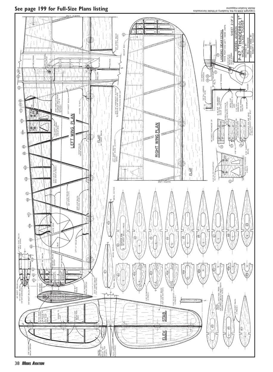
Wing
The P-47's wing is constructed with the Lost-Foam Wing Building System that Bob Hunt devised many years ago. I have built several wings using this method, including two of my Thunderbolts and the second Geo-XL. It is the only wing-building system I know of that keys on the outside shape of the wing rather than a centerline. This yields a much more accurate finished wing.
With the Lost-Foam system a foam blank of the desired wing panel is positioned atop a drawing of the desired built-up wing. The rib positions are lofted perpendicular to the tabletop on the front and back of the blank. The templates are attached and the core is cut in the normal foam-wing manner.
The spar locations are transferred from the template to the core, and the core is sanded. The spar-location marks are connected with a straightedge and a pen. This is done on the top and bottom of the core. The rib positions that were marked on the front and back of the blank are connected using a flexible straightedge, and the rib locations are drawn on the top surface of the core. Then the entire plan of the wing is accurately drawn out in the lower cradle half, including the spar location, the ribs, and the trailing-edge position.
The core is accurately cut apart into rib templates from which perfectly shaped ribs can be generated. Then the wing is built in the lower cradle half. The cradles (portions of the original foam blank from which the core was cut) are just as accurate negative representations of the wing shape as the core is a positive shape.
A complete how-to covering the Lost-Foam technique would take many pages of text and photos. A DVD/video set that takes the viewer through the entire process step by step is available from Robin's View Productions. Also available from Robin's View Productions are the Lost-Foam Wing Building System components for the P-47, to allow you to build your own wings. The company also provides a custom building service that constructs the wing for you using the Lost-Foam system.
We are beginning to see a shift in the old accepted building paradigms, and each of these new methods yields more accurate, simpler-to-build, and repeatable models. Things are improving.
Stabilizer and Elevators
The method I used to build the stabilizer and elevators is perhaps different from the norm. It is simple and yields quick, accurate, and rigid parts.
I cut the outline of the parts from straight pieces of 3/8" medium-light "C"-grain balsa. Then I cut out the inside so that there is a "frame" of balsa with an open area in the middle.
The elevators need to be fully tapered before sheeting, but only the tips require tapering on the stabilizer. I install 3/32" balsa ribs per the plans and then sheet both sides of the stabilizer and both sides of each elevator with 1/16" balsa. I prefer to use thinned aliphatic resin glue (Titebond or Elmer's) for this process. All the sheeting and the core parts need to be cut before this process begins. The components need to be sheeted against a flat surface. I do it the following way:
- Lay a sheet of waxed paper on the flat surface. Place the 1/16" sheeting on the waxed paper and apply glue to the side of the core that corresponds to that sheeting piece.
- Quickly and carefully align the core on the sheeting piece. Immediately apply glue to the upper surface of the balsa core piece, and then carefully position the top piece of sheeting on the core.
- Lay a flat board on top of this assembly, and add enough weight to press the pieces together securely. Let this dry thoroughly.
I do not glue the sheeting to the stabilizer tips where they taper during the process I just described. After the glue is dry I brush thinned aliphatic glue onto the tapered areas, reweight the assembly on the flat surface, and use tapered balsa shims to force the sheeting to conform to the tapered area at the tips.
All that is left to do is round the edges and assemble the parts in the usual manner. This process yields an accurate, rigid stabilizer-and-elevator assembly. My assemblies typically weigh 2.25–2.50 ounces, including the horn and hinges.
Compression Pieces
The only other item to discuss is the use of vertical compression pieces that transfer the vibration and rotational torque effect of the engine from the engine-mount assembly out to the molded-balsa shells.
It is imperative to install these pieces when assembling the formers to the forward section of the fuselage. The plans, and especially the accompanying isometric cutaway drawing, depict these parts and their location.
I install these pieces after the upper fuselage formers have been positioned and glued to their corresponding formers in the fuselage crutch assembly. Note that the grain runs vertically on these pieces, effectively establishing them as shear webs.
I install these pieces so that they stick up slightly above the tops of the formers and then carefully sand them to perfectly fit the outside of the formers. This also means that the taper of the fuselage at that point is reflected in the angle of the webs. Now the top molded sheeting piece will make solid contact when installed. The message is clear: take the time to fit these pieces properly.
The idea to use these pieces came from my good friend Al Rabe, who has done more research and development on the molded-shell type of fuselage construction than anyone else I'm aware of.
Finishing
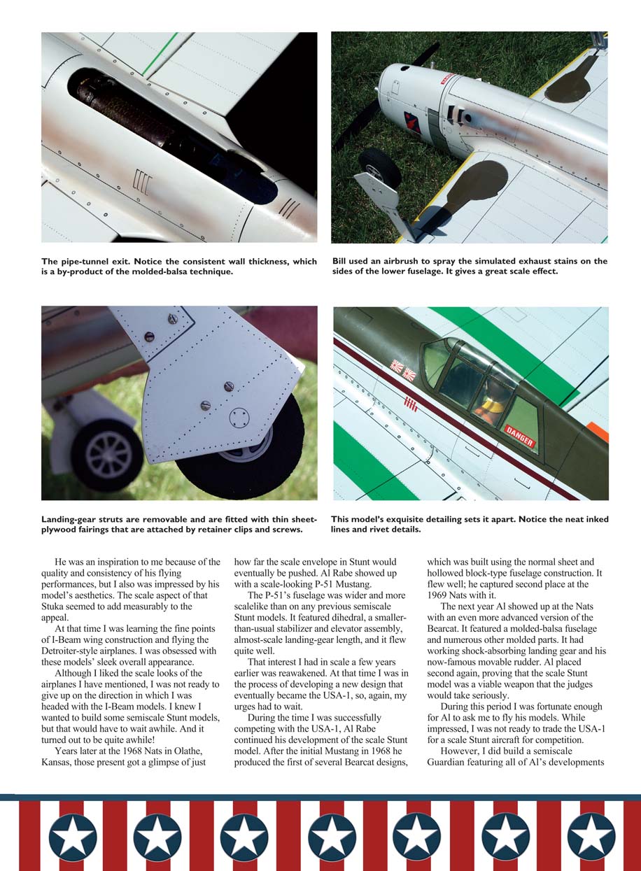
I apply .02 carbon-fiber mat on the fuselage and the flaps for strength and rigidity. I obtain this material from Aerospace Composite Products.
Some modelers prefer to cover the entire airframe with the mat, but I do not feel this is necessary with the inherently strong wing and tail assemblies we are using. My old buddy Bob Gieseke prefers to cover the entire airframe when he finishes his models, but he's old enough to be carbon-dated himself.
I cover the wing and tail assemblies with Japanese tissue and then proceed with a standard dope/paint finish. I use Aero Fill from Aero Products to mix the filler coat. It is the lightest and easiest-to-sand filler material I have found.
The multicolored panel effect was achieved by mixing light-gray dope with a bit of silver dope. I mix several batches that have subtle differences in the shades. I thin them slightly and spray them on with the airbrush using a low-pressure setting. I mask off areas with strips of paper and spray the panels. The result is a subtle paneling effect. I intend to write a complete article on this technique in the future.
I use a clear-dope topcoat but spray the nose area and a bit of the wing's leading edge on either side of the fuselage with catalyzed clear polyurethane for protection against fuel spillage.
Flying
My Thunderbolt is currently set up to fly with a PA .61 or PA .65 engine, but as this is being written I am getting ready to install a PA .75 and test the model with that.
I test-flew one of the .75s in Bob McDonald's P-47 and was extremely impressed with the engine's power and controllability. If you are looking for maximum performance, I strongly recommend that you use the .75 in this model.
Looking back at the past 12 years I've been designing and building these P-47 semiscale Stunt models, I believe I've found a formula for performance that I'm happy to be able to pass on to others. All these models have flown wonderfully. A great deal of this can be attributed to the inherent rigidity of the molded-shell type construction coupled with the wider fuselage cross-section. It's almost pure strength!
However, there's more to the formula than one factor. Bob Hunt and I often discuss and agree on the fact that there are five major attributes a Stunt model must possess to be successful:
- It must be lightweight.
- It must be accurate.
- It must be rigid. Rigidity and accuracy go hand in hand because if the model is accurate on the bench but twists torsionally in flight, it is not truly accurate.
- It must have a consistent and powerful propulsion system that the modeler knows how to adjust and tune.
- It must have a robust and adjustable control system that can stand up to the loads imposed during flight and deliver accurate and smooth control inputs.
All those things need to be incorporated into a proper aerodynamic package. This is where I feel that future development will yield superior airplanes. And the quest continues.
I thank Bob Sweitzer for consenting to produce the inked plans for my P-47. His work is outstanding. Bob's beautiful cutaway drawing of the Thunderbolt should help answer any building questions. He's a true artist!
Sources
- Aero Fill filler-coat material; PA .61, .65, .75 engines:
Aero Products 980 Winnbrook Dr. Dacula, GA 30019 (678) 407-9376 www.aeroproduct.net
- .02 carbon mat:
Aerospace Composite Products (925) 443-5900 www.acpsales.com
- Straight Form and Compound Curve Balsa Molding Techniques DVD/video; Lost-Foam Wing Building System DVD/video set; Lost-Foam Wing System sets; prebuilt Masterflite wings:
Robin's View Productions Box 68 Stockertown, PA 18083 (610) 746-0106
Transcribed from original scans by AI. Minor OCR errors may remain.

