
AERONCA Sedan
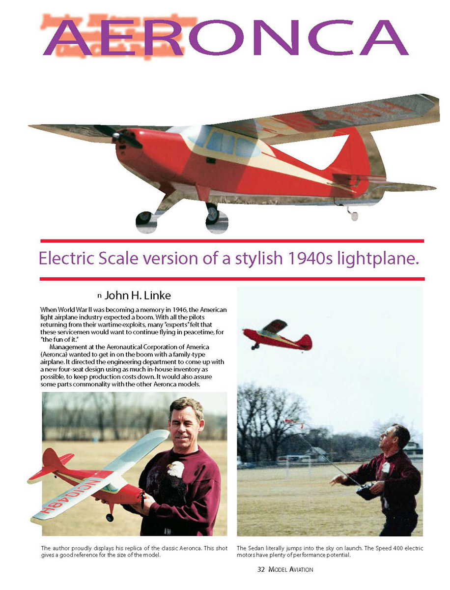
Electric scale version of a stylish 1940s lightplane.
by John H. Linke
When World War II was becoming a memory in 1946, the American light airplane industry expected a boom. With all the pilots returning from their wartime exploits, many "experts" felt that these servicemen would want to continue flying in peacetime, for "the fun of it."
Management at the Aeronautical Corporation of America (Aeronca) wanted to get in on the boom with a family-type airplane. It directed the engineering department to come up with a new four-seat design using as much in-house inventory as possible, to keep production costs down. It would also assure some parts commonality with the other Aeronca models.
The four-seat Aeronca Sedan was the result of this effort. Powered by a 145-horsepower Continental engine, the 37-foot wingspan aircraft carried its passengers in comfort at about 105 mph. Although it wasn't particularly fast—even in its heyday—the Sedan excelled in load-carrying. The aircraft's reasonable cost and all-metal wing made it a favorite of operators in isolated areas.
Aeronca manufactured 561 Sedans from mid-1948 through March 1951. Two last airplanes were built from spares in October 1951, thus ending Aeronca's aircraft manufacturing business; Aeronca later became involved in aerospace component manufacturing.
Data from 1980 Federal Aviation Administration (FAA) records indicate that 197 Sedans were still registered in the U.S., with perhaps another 100 in Canada performing various utility duties.
The Sedan's standard factory color scheme was limited to three variants during production:
- 1948 and 1949 models: red and straw (cream). The 1948 models had natural aluminum-colored wings; a later service bulletin required painted wings.
- 1949: red wings with NC numbers on the top right and bottom left in the straw color.
- 1950: medium blue over straw, blue wings, and straw numbers on the wings.
For purists, Sedans were numbered consecutively from NC1000H to NC1491H. Many aircraft were exported, so surviving examples may carry other identification numbers or different paint schemes.
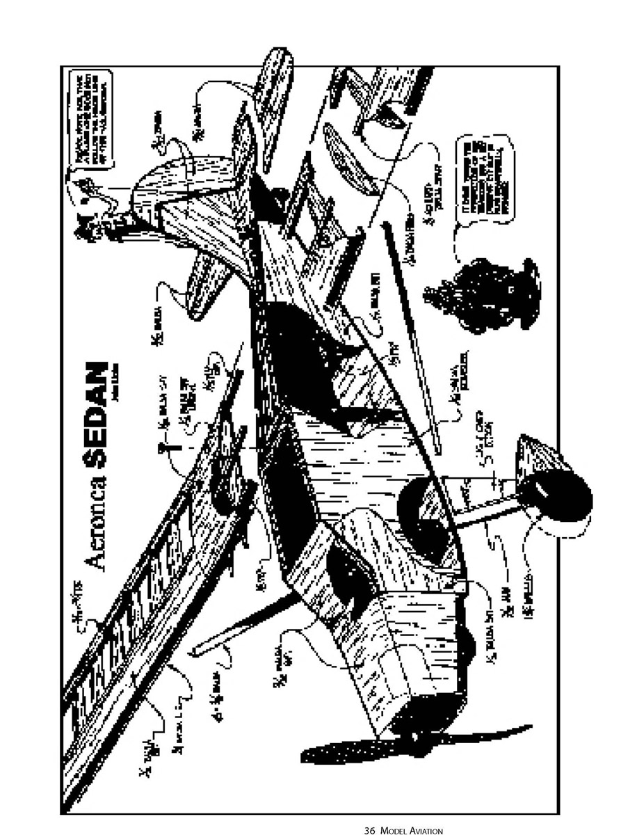
CONSTRUCTION
I have been influenced by the efforts of Walt Musciano in the model's layout and general construction features. A few Sedans have been modeled through the years: Berkeley had a kit in the 1950s, and another version was advertised in early issues of Radio Control Modeler. Walt Musciano had a control-line model featured in his book Building and Flying Scale Model Aircraft; Scientific may have produced that or a similar kit.
My Electric Sedan is a simple three-channel sport flier that looks like a full-scale airplane in the air. The electronic speed control permits longer flights by allowing the Speed 400 motor to be throttled back for extended cruising. The model is not a speed demon nor fully aerobatic; it is designed to be easy to fly in a scale-like fashion and has generally good manners.
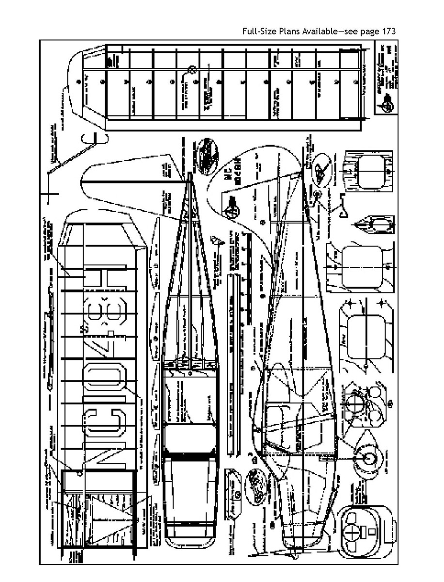
The wings may be attached with the dowel-and-bolt arrangement shown on the plans or the more-traditional dowel-and-rubber-band arrangement.
Battery packs are many and varied. I use Radio Shack 850/1,000 mAh AA Ni-Cd packs. They are more than satisfactory for fun-flying, readily available, and simple to install on a slide tray. There is no need to carry an airborne Battery Eliminator Circuit (BEC) receiver pack, which further reduces the weight the wing must carry.
Check controls before each flight!
This airplane launches easily by hand. Don't throw it; ease it into the air with a smooth follow-through. Allow the model to accelerate to climbing speed before trying any turns.
Fuselage
This is a simple balsa box with an open, stringered rear section. Plywood is used in areas of stress. The model is not designed to survive a major ground impact; increasing wood sizes will only make it too heavy to fly well with electric or small gas power.
- Wood selection is not particularly critical, but try to keep similar densities in the fuselage sides and doublers to make bending easier.
- Tail surfaces are made from medium-weight 3/32-inch balsa sheet. They may be built up for lightness, but be careful not to introduce warps when covering.
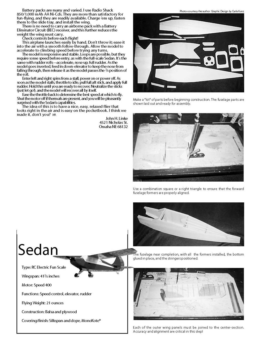
- The easiest way to build from scratch is to make a "kit" of components: cut fuselage sides and doublers from medium-weight 1/16-inch balsa. Note that the doublers have vertical grain. Edge-glue three-inch-wide sheets together with CyA for speed.
- Cut the firewall, landing-gear braces, and formers 1 and 2 from 1/8-inch plywood. These pieces hold the airplane together—don't skimp.
- Drill 1/16- or 3/32-inch-diameter pilot holes in former 1 for the wing hold-down dowels.
- Remaining formers can be cut from scrap 3/32-inch balsa or laminated from 1/16-inch stock.
- Cut the keel piece—to support the vertical and horizontal stabilizer—from 1/8-inch medium balsa. Leave it slightly long at the forward end; trim later.
- Stringers are 3/16-inch-square balsa; use hard balsa stock as they take some abuse during covering.
Assembly steps (summary):
- Glue doublers in place with CyA. If you use white glue or aliphatic resin, weight the sides on a flat surface until dry to minimize warpage.
- Mark the location of all formers from the top-view plan.
- The down-thrust angle on the firewall is noncritical; ensure it is down-thrust rather than up-thrust to compensate for motor torque.
- Cut triangular stock and wing rest from 1/8-inch balsa; glue to fuselage sides. Epoxy formers 1 and 2 to one side, square it, then epoxy the other side in place.
- Glue a 1/8-inch-square spacer to the lower front side of former 1 to position the landing-gear brace. Cut a groove in each LG brace to fit the gear wire and epoxy one brace in place.
- Cut, fit, and glue 1/8-inch bottom sheeting between formers 1 and 2 (cross-grain). When dry, pull the tail together sandwiching the keel piece and check squareness at the wing mount.
- Use the keel to help align formers 3 and 4. When satisfied, glue the sides to the keel and clamp until dry.
- Fit scrap 1/8- or 1/16-inch plywood between former 4 and the tail post. Bend the .045-inch-diameter tail-wheel wire to shape and glue it to this plywood piece; glue tail-wheel mount in place flush with fuselage sides.
- Cut and glue fuselage bottom pieces cross-grain, then fit and glue 3/32-inch stringers.
- Mount the Graupner Speed 400 motor mount to the firewall. Cut a 1/8-inch-diameter hole in the firewall so the motor can be removed from the rear; enlarge as necessary for easy passage.
- Epoxy the firewall in place, pulling the nose section together with rubber bands. Check firewall alignment before epoxy sets—no up-thrust or left-thrust allowed!
- Cut slots in fuselage sides for landing-gear wire, sandwich the wire between LG pieces, epoxy and clamp. Cover the bottom from landing gear to cowl with 1/16-inch balsa and the forward part with 3/32-inch balsa (cross-grain).
- Cut tail surfaces from medium 3/32-inch balsa. Sand and round the fin, rudder, horizontal stabilizer, and elevator edges. Use a 1/8-inch-diameter hardwood dowel to join elevator halves. Hinge elevators with over/under cloth hinges or Monokote hinges. Do not hinge rudder to the vertical fin yet.
- Position the horizontal stabilizer assembly in the keel slot and check alignment with the wing rest. Ensure stabilizer is parallel to the wing and 90° to the fuselage in top view. Alignment is critical for a successful first flight; glue when satisfied.
- Install motor, placing the electronic speed control behind the firewall. Tape wires to fuselage sides to keep the motor area clear.
- Shape the nose with spoke shave, knife, and sandpaper to match the plan. The nose block may be one piece or laminated; keep it light and hollow as indicated. Cut the 1/8-inch-diameter hole for the motor and fit the nose block, tack-gluing and blending into the contour.
- Epoxy in the 1/8-inch plywood wing-bolt mount. Fit scrap balsa behind former 2 to prevent punching through the covering with a screwdriver.
- Servos are mounted at the rear of the cabin just ahead of former 2. Cut pushrods for tail surfaces—3/32-inch balsa with wire ends, clevis in rear and "Z" bends at the servo.
- Glue scrap 3/32 x 1/4-inch balsa between formers on the upper fuselage sides to minimize distortion when shrinking covering.
Wing construction
Wing construction is straightforward.
- The center-section is sheeted with 1/16-inch balsa on the bottom and 1/32-inch balsa on the top. If you plan to use rubber bands for securement, use 1/8-inch balsa on the top as well.
- Cut all ribs, trailing-edge pieces, the 1/8-inch-square spar, and the 1/4-inch-square leading edge (LE). Lay a 1/16 x 1/2-inch balsa LE on the plan and glue the 1/4-inch LE to it. Pin the trailing edge (TE) to the plan and raise the tips as indicated.
- Fit ribs and glue in place. Leave rib 8 off until outer panels join the center-section. Glue the spar in place and allow assembly to dry thoroughly before removing from the plan.
- Build the other panel similarly. For the center-section, cut the LE to provide dihedral supports. Edge-glue 1/16-inch balsa to make up the lower sheeting; pin the TE to the plan and edge-glue the lower sheeting to the TE. Glue the LE to the lower sheeting.
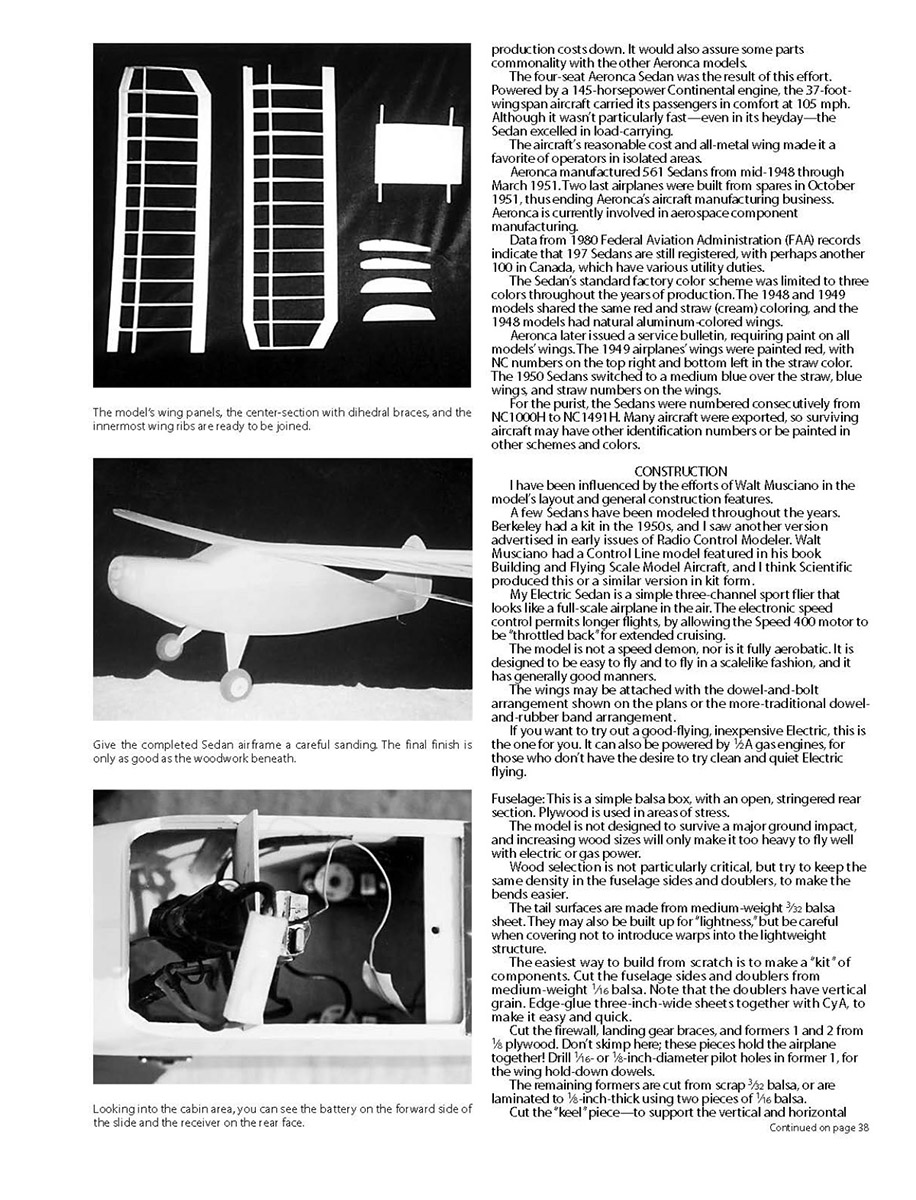
- Glue epoxy pre-formed 1/16-inch plywood dihedral joiners to the LE and TE, ensuring each joiner is equidistant from the building board.
- Shape the center-section LE with a spoke shave and sandpaper, fit 1/32-inch sheeting, and mate the outer panels to the center-section one at a time. Support the tip one inch above the board at the last rib and glue dihedral braces to the outer panel. Fit and glue rib 8. Repeat for the other panel.
- Fit and glue LE sheeting to each wing panel. Tips may be cut from 3/32-inch soft balsa or laminated. Trim and sand the entire wing assembly—go easy on sanding the 1/32-inch sheeting.
- Fit the wing to the fuselage, ensuring it is parallel with the horizontal stabilizer. Temporarily secure the wing with tape or rubber bands. Drill a 3/16-inch-diameter hole through the pilot holes in former 1—this will leave a mark on the bottom of the wing.
- Remove the wing and cut two pieces of 3/16-inch-square triangular stock. Sand or cut a 3/16-inch groove in the stock to accept the dowel. Spot-glue dowels to the wing and reposition the wing. If fit is satisfactory, remove the wing and glue the dowels in place. Glue triangular stock over the dowels for reinforcement.
- Drill a 1/8-inch-diameter hole through the center-section TE into the plywood bolt mount. Tap the plywood bolt mount with a 10-32 tap, drill the TE hole to 3/16-inch, and strengthen it with CyA or plywood scrap. Fit the wing, screw the bolt in place, and check alignment.
- When satisfied, fit and glue the final piece to the windshield and sand to contour with the center-section LE. Remove the wing and finish shaping the windshield.
- Sand the whole fuselage with 280-grit (or finer) paper, smoothing and lightly rounding the bottom.
Final Assembly and Finish
- Glue on the vertical fin with epoxy or CyA; the gluing area is small.
- Cover the fuselage and cut a small portion of covering away on the keel so the vertical fin may be glued in place. This yields a smooth fillet line like the full-scale Sedan.
- Hinge the rudder in place with over/under flanges or Monokote. Cover open areas with silkspan, silk, iron-on film, or 1/32-inch balsa.
- On the original model, silkspan was applied and doped: two coats of dope, sand with 320-grit between coats, then sanding sealer and more sanding. Finish with two to three coats of butyrate, sand with 400 grit, then add color.
- After masking, spray a silver base coat and then the color. Wings may be covered with aluminum MonoKote and numbers done with MonoKote Trim Sheets.
- Install servos at the rear of the wing bay, fit pre-fitted pushrods, and check for free operation.
- The receiver may be fitted to the rear of the 1/8-inch plywood slide that also carries the flight batteries. Leave enough wire to allow slide removal for battery replacement. The slide's springiness absorbs much impact in a nose-first landing, protecting forward structure.
- If the battery pack is installed on the fuselage floor, reinforce locally with 1/32-inch plywood and Velcro the battery to the reinforcement. Place foam rubber between the battery and former 1 to absorb impact.
- Gear fairings can be glued to the wire; rough up the wire with sandpaper and keep fairings slightly clear of the fuselage so they may flex on landing. A bead of silicone at the fairing–fuselage junction simulates the real Sedan fillet.
- Wheel pants can be made by laminating 3/32-inch soft balsa to thickness and carving to shape. Secure wheel pants to the gear fairing with epoxy, or solder a mount plate to the gear leg and screw the wheel pants to the plate with cut-down #2 sheet-metal screws.
Balance the model as indicated on the plans. Use the flight pack to achieve final balance if necessary. The prototype balanced satisfactorily with the flight pack, receiver, speed control, and servos in the described positions. All-up weight should be less than 24 ounces for best performance; the original weighed 21 ounces ready to fly (with a six-cell power pack).
Note: The model flies "on the wing"—not on motor power—and any increase above recommended weight only adds to trimming. Climb performance depends on power in excess of level-flight requirement; the higher the wing loading, the more power required.
Many electric models don't fly well because modelers build in more strength than necessary. Electric models are not subject to the same engine vibration as glow/gas models and should be built light for best performance. The relatively heavy battery pack can cause severe damage if it breaks loose in a hard landing—secure it well.
Flying
- Check controls before each flight.
- Launch by hand with a smooth follow-through; do not throw. Allow acceleration to climbing speed before turning.
- The model is responsive and stable. Loops are possible but require speed before entry, as with the full-scale Sedan.
- Rudder rolls: accelerate, raise nose, apply full rudder. As the model goes inverted, feed in down-elevator to keep the nose from falling, then release as the model passes about 3/4 of the roll.
- Spins: enter from a stall, power on or off. As soon as the model stalls, throttle to idle, pull full aft stick, and apply full rudder. Hold until ready to recover. Neutralize the sticks (let go) and the model will recover by itself.
- Ease the throttle back to determine the best speed for cruise. Shut the motor off if thermals are present—glides can be surprisingly good.
The intent is a nice, easy, relaxed flier that looks right in the air and is easy on the pocketbook.
John H. Linke 4521 Nicholas St. Omaha, NE 68132
Specifications
- Type: RC Electric Fun Scale
- Wingspan: 41-3/4 inches
- Motor: Speed 400
- Functions: Speed control, elevator, rudder
- Flying weight: 21 ounces (prototype), recommended less than 24 ounces
- Construction: Balsa and plywood
- Covering/finish: Silkspan and dope, MonoKote
Transcribed from original scans by AI. Minor OCR errors may remain.

