
AEROWORKS 30CC LASER 200 ARF
Tom Sullivan [email protected]
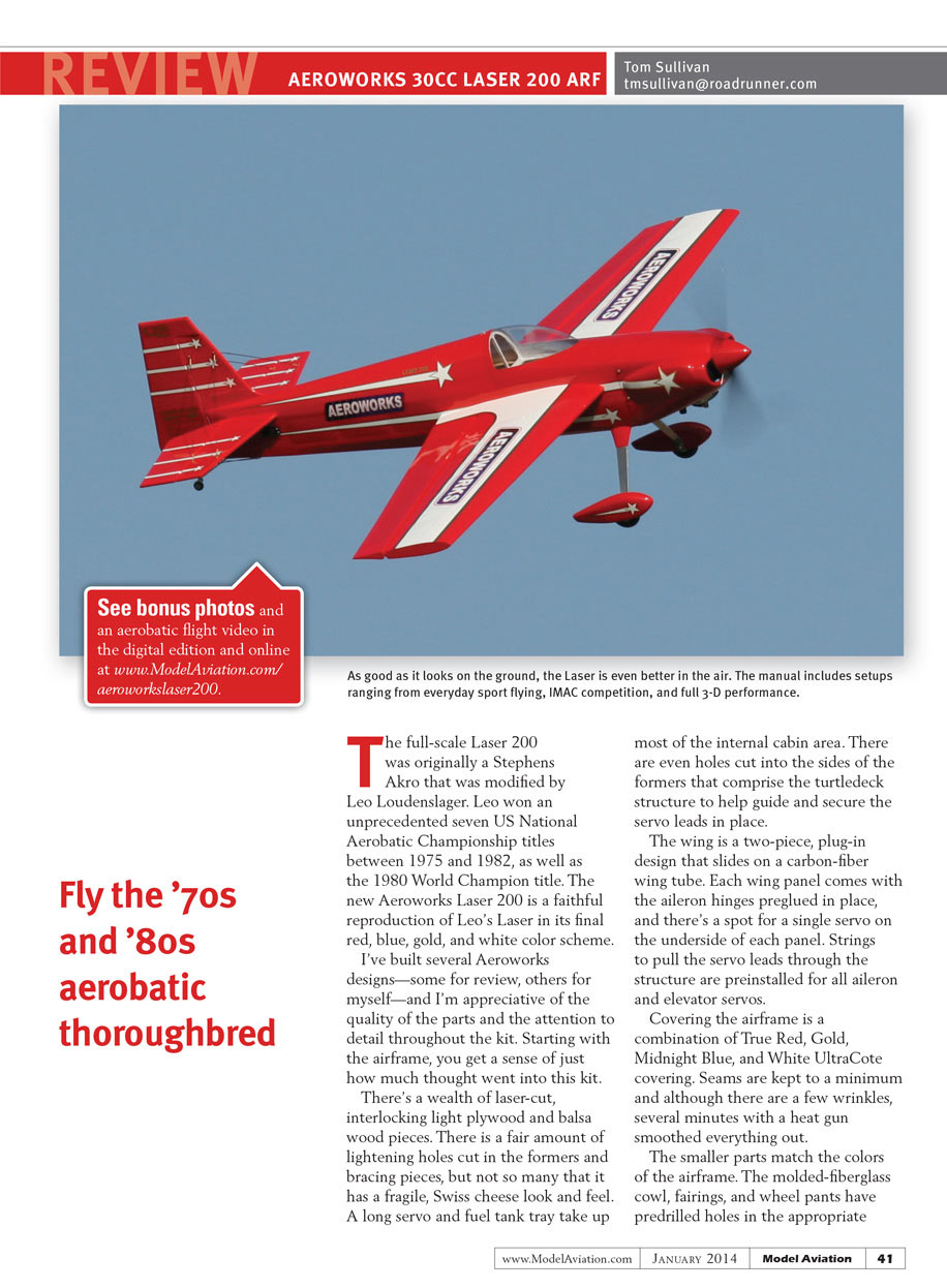
The full-scale Laser 200 was originally a Stephens Akro that was modified by Leo Loudenslager. Leo won an unprecedented seven US National Aerobatic Championship titles between 1975 and 1982, as well as the 1980 World Champion title. The new Aeroworks Laser 200 is a faithful reproduction of Leo’s Laser in its final red, blue, gold, and white color scheme.
I’ve built several Aeroworks designs—some for review, others for myself—and I’m appreciative of the quality of the parts and the attention to detail throughout the kit. Starting with the airframe, you get a sense of just how much thought went into this kit.
There’s a wealth of laser-cut, interlocking light-plywood and balsa wood pieces. There is a fair amount of lightening holes cut in the formers and bracing pieces, but not so many that it has a fragile, Swiss-cheese look and feel. A long servo and fuel-tank tray take up most of the internal cabin area. There are even holes cut into the sides of the formers that comprise the turtledeck structure to help guide and secure the servo leads in place.
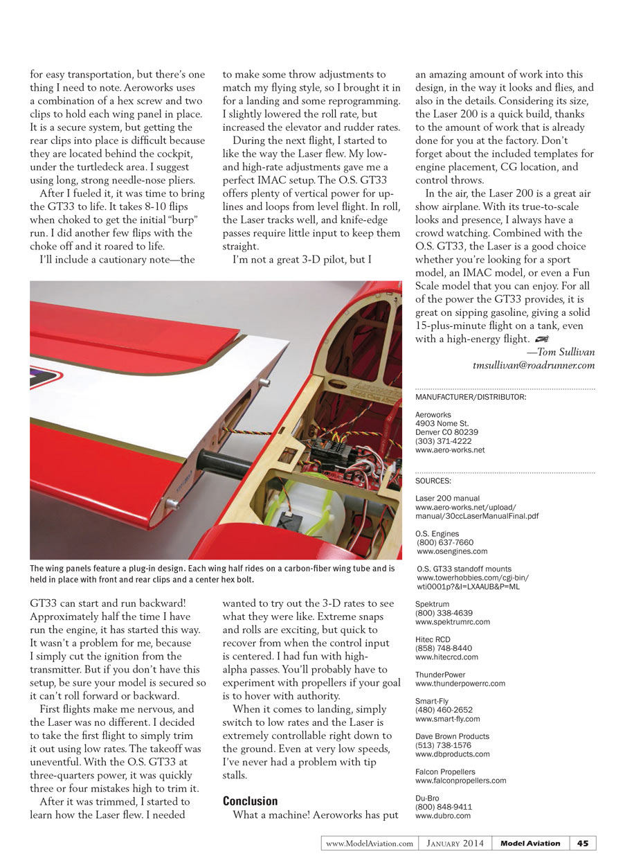
The wing is a two-piece, plug-in design that slides on a carbon-fiber wing tube. Each wing panel comes with the aileron hinges preglued in place, and there’s a spot for a single servo on the underside of each panel. Strings to pull the servo leads through the structure are preinstalled for all aileron and elevator servos.
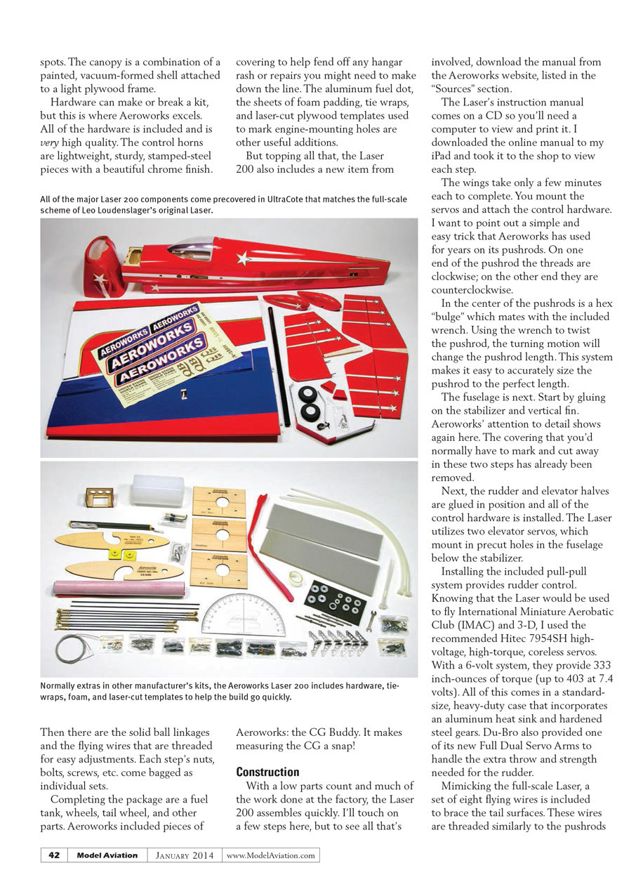
Covering the airframe is a combination of True Red, Gold, Midnight Blue, and White UltraCote covering. Seams are kept to a minimum and although there are a few wrinkles, several minutes with a heat gun smoothed everything out.
The smaller parts match the colors of the airframe. The molded-fiberglass cowl, fairings, and wheel pants have predrilled holes in the appropriate spots. The canopy is a combination of a painted, vacuum-formed shell attached to a light plywood frame.
Hardware can make or break a kit, but this is where Aeroworks excels. All of the hardware is included and is very high quality. The control horns are lightweight, sturdy, stamped-steel pieces with a beautiful chrome finish.
There are solid ball linkages and flying wires that are threaded for easy adjustments. Each step’s nuts, bolts, screws, etc., come bagged as individual sets.
Completing the package are a fuel tank, wheels, tail wheel, and other parts. Aeroworks included pieces of covering to help fend off any hangar rash or repairs you might need to make down the line. The aluminum fuel dot, the sheets of foam padding, tie wraps, and laser-cut plywood templates used to mark engine-mounting holes are other useful additions.
But topping all that, the Laser 200 also includes a new item from Aeroworks: the CG Buddy. It makes measuring the CG a snap!
Construction
With a low parts count and much of the work done at the factory, the Laser 200 assembles quickly. I’ll touch on a few steps here, but to see all that’s involved, download the manual from the Aeroworks website (listed in the "Sources" section).
The Laser’s instruction manual comes on a CD, so you’ll need a computer to view and print it. I downloaded the online manual to my iPad and took it to the shop to view each step.
The wings take only a few minutes each to complete. You mount the servos and attach the control hardware. I want to point out a simple and easy trick that Aeroworks has used for years on its pushrods. On one end of the pushrod the threads are clockwise; on the other end they are counterclockwise.
In the center of the pushrods is a hex "bulge" which mates with the included wrench. Using the wrench to twist the pushrod, the turning motion will change the pushrod length. This system makes it easy to accurately size the pushrod to the perfect length.
The fuselage is next. Start by gluing on the stabilizer and vertical fin. Aeroworks’ attention to detail shows again here. The covering that you’d normally have to mark and cut away in these two steps has already been removed.
Next, the rudder and elevator halves are glued in position and all of the control hardware is installed. The Laser utilizes two elevator servos, which mount in precut holes in the fuselage below the stabilizer.
Installing the included pull-pull system provides rudder control.
Knowing that the Laser would be used to fly International Miniature Aerobatic Club (IMAC) and 3-D, I used the recommended Hitec 7954SH high-voltage, high-torque, coreless servos. With a 6-volt system, they provide 333 inch-ounces of torque (up to 403 at 7.4 volts). All of this comes in a standard-size, heavy-duty case that incorporates an aluminum heat sink and hardened steel gears. Du-Bro also provided one of its new Full Dual Servo Arms to handle the extra throw and strength needed for the rudder.
Mimicking the full-scale Laser, a set of eight flying wires is included to brace the tail surfaces. These wires are threaded similarly to the pushrods mentioned earlier, so adjusting them to the correct length is simple.
Now it's time to get the Laser on its feet. The main gear strut is a thick aluminum piece with everything drilled so it bolts in place; then the fairings are glued in place using silicone sealant. After that, the wheels and wheel pants are quickly installed, the tail wheel bolted into place, and the springs attached to the rudder.
Powering the Laser 200 is an O.S. GT33 engine. This two-stroke gasoline engine is similar in design to a large O.S. glow engine, but features a large canister muffler that wraps around to the rear of the engine above the carburetor, which is also on the back of the case (rear intake).
Four mounting lugs provide a radial-type engine mount; however, the standoffs are not included with the engine. I had to put in a quick order with Tower Hobbies for these, so if you go this route, they are listed in the "Sources" section. After you have the standoffs, use the included DLE-30cc template for the correct bolt spacing.
When the engine and ignition box are mounted, it's time to fit the cowl and cut out the clearance for the cylinder head, muffler, and cooling exhaust flow. The cowl comes with predrilled mounting holes. I made a template for the cutout, used it to mark the cowl, and then finished it using my rotary tool.
I slightly modified the muffler by cutting approximately 3/4 inch off the exhaust stack. It still extends nicely outside of the cowl, but it is easier to attach and remove the cowl.
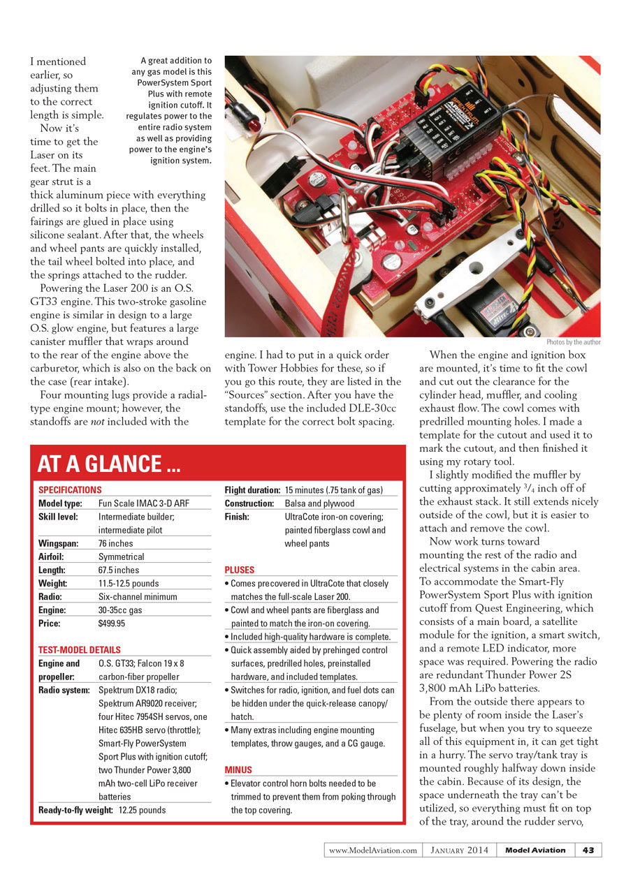
Now work turns toward mounting the rest of the radio and electrical systems in the cabin area. To accommodate the Smart-Fly PowerSystem Sport Plus with ignition cutoff from Quest Engineering—which consists of a main board, a satellite module for the ignition, a smart switch, and a remote LED indicator—more space was required. Powering the radio are redundant Thunder Power 2S 3,800 mAh LiPo batteries.
From the outside there appears to be plenty of room inside the Laser's fuselage, but when you try to squeeze all of this equipment in, it can get tight in a hurry. The servo tray/tank tray is mounted roughly halfway down inside the cabin. Because of its design, the space underneath the tray can't be utilized, so everything must fit on top of the tray around the rudder servo, the throttle servo, and the fuel tank.
The most obvious place to fit the main board of the Smart-Fly system was between the rudder servo and the wing-tube socket. Because of the large throw of the rudder servo’s extended arm, I had to make a standoff from some scrap light plywood to raise the Smart-Fly board roughly an inch above the servo tray.
The LiPo batteries could go in several places, but I wanted to check the CG before mounting them. I attached the included CG Buddy. This consists of two ribbed-shaped pieces of plywood with cutouts that allow them to slide over the wing antirotation pins and the wing tube.
The other part is the handle that has a rope with loops tied in both ends. These loop ends slide over pins on the rib pieces. With the CG Buddy assembled and with everything else (wings, canopy, cowl) fitted roughly in place, you can easily lift the handle and see where the Laser balances. Using this I could easily move the batteries around to get the perfect balance, which turned out to be with both batteries up against the firewall.
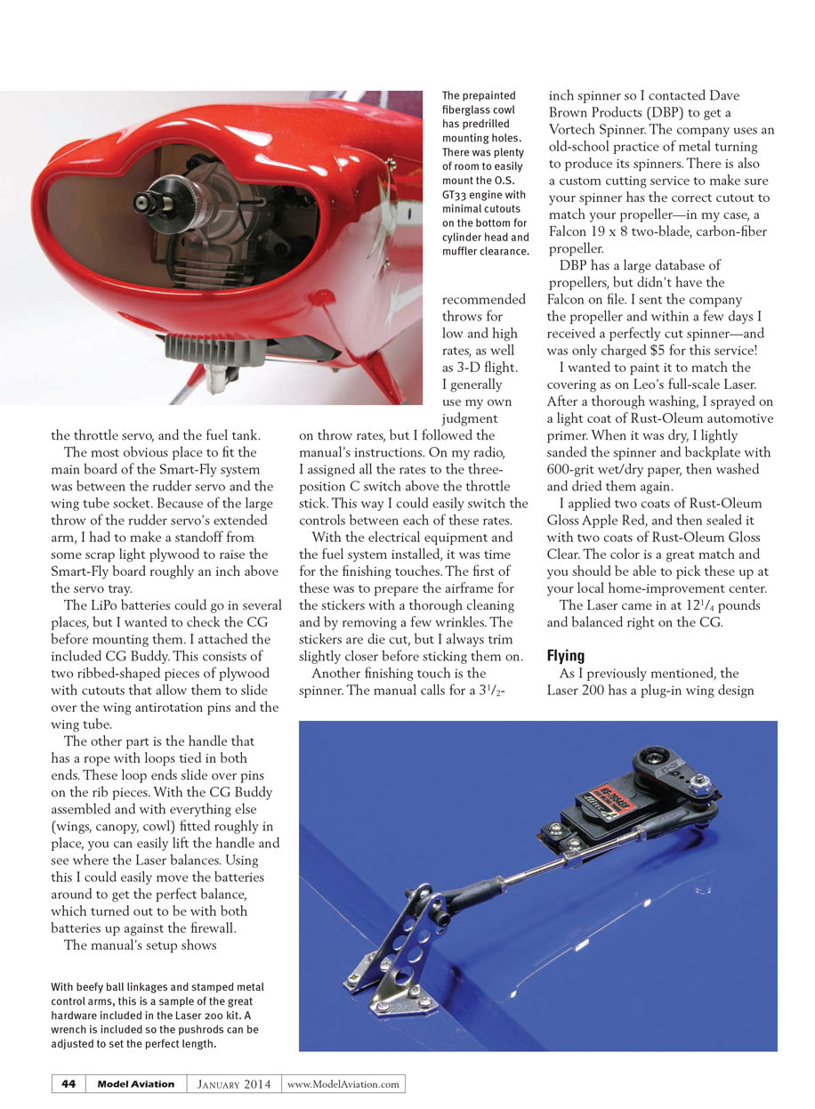
The prepainted fiberglass cowl has predrilled mounting holes. There was plenty of room to easily mount the O.S. GT33 engine with minimal cutouts on the bottom for cylinder head and muffler clearance.
The manual’s setup shows recommended throws for low and high rates, as well as 3-D flight. I generally use my own judgment on throw rates, but I followed the manual’s instructions. On my radio, I assigned all the rates to the three-position C switch above the throttle stick. This way I could easily switch the controls between each of these rates.
With the electrical equipment and the fuel system installed, it was time for the finishing touches. The first of these was to prepare the airframe for the stickers with a thorough cleaning and by removing a few wrinkles. The stickers are die cut, but I always trim slightly closer before sticking them on.
Another finishing touch is the spinner. The manual calls for a 3-1/2-inch spinner, so I contacted Dave Brown Products (DBP) to get a Vortech spinner. The company uses an old-school practice of metal turning to produce its spinners. There is also a custom cutting service to make sure your spinner has the correct cutout to match your propeller—in my case, a Falcon 19 x 8 two-blade carbon-fiber propeller.
DBP has a large database of propellers, but didn’t have the Falcon on file. I sent the company the propeller and within a few days I received a perfectly cut spinner—and was only charged $5 for this service!
I wanted to paint it to match the covering as on Leo’s full-scale Laser. After a thorough washing, I sprayed on a light coat of Rust-Oleum automotive primer. When it was dry, I lightly sanded the spinner and backplate with 600-grit wet/dry paper, then washed and dried them again.
I applied two coats of Rust-Oleum Gloss Apple Red, and then sealed it with two coats of Rust-Oleum Gloss Clear. The color is a great match and you should be able to pick these up at your local home‑improvement center.
The Laser came in at 12.25 pounds and balanced right on the CG.
AT A GLANCE ...
SPECIFICATIONS
- Model type: Fun Scale IMAC 3-D ARF
- Skill level: Intermediate builder; intermediate pilot
- Wingspan: 76 inches
- Airfoil: Symmetrical
- Length: 67.5 inches
- Weight: 11.5–12.5 pounds
- Radio: Six-channel minimum
- Engine: 30–35cc gas
- Price: $499.95
TEST-MODEL DETAILS
- Engine and propeller: O.S. GT33; Falcon 19 x 8 carbon-fiber propeller
- Radio system: Spektrum DX18 radio; Spektrum AR9020 receiver; four Hitec 7954SH servos; one Hitec 635HB servo (throttle); Smart-Fly PowerSystem Sport Plus with ignition cutoff; two Thunder Power 3,800 mAh two-cell LiPo receiver batteries
- Ready-to-fly weight: 12.25 pounds
- Flight duration: 15 minutes (≈0.75 tank of gas)
- Construction: Balsa and plywood
- Finish: UltraCote iron-on covering; painted fiberglass cowl and wheel pants
PLUSES
- Comes precovered in UltraCote that closely matches the full-scale Laser 200.
- Cowl and wheel pants are fiberglass and painted to match the iron-on covering.
- Included high-quality hardware is complete.
- Quick assembly aided by prehinged control surfaces, predrilled holes, preinstalled hardware, and included templates.
- Switches for radio, ignition, and fuel dots can be hidden under the quick-release canopy/hatch.
- Many extras including engine mounting templates, throw gauges, and a CG gauge.
MINUS
- Elevator control-horn bolts needed to be trimmed to prevent them from poking through the top covering.
Flying
The Laser 200 has a plug-in wing design for easy transportation, but there’s one thing to note. Aeroworks uses a combination of a hex screw and two clips to hold each wing panel in place. It is a secure system, but getting the rear clips into place is difficult because they are located behind the cockpit, under the turtledeck area. I suggest using long, strong needle-nose pliers.
After I fueled it, it was time to bring the GT33 to life. It takes 8–10 flips when choked to get the initial “burp” run. I did another few flips with the choke off and it roared to life.
A cautionary note—the GT33 can start and run backward! Approximately half the time I have run the engine, it has started this way. It wasn’t a problem for me because I simply cut the ignition from the transmitter. But if you don’t have this setup, be sure your model is secured so it can’t roll forward or backward.
First flights make me nervous, and the Laser was no different. I decided to take the first flight to simply trim it out using low rates. The takeoff was uneventful. With the O.S. GT33 at three-quarters power, it was quickly three or four mistakes high to trim it.
After it was trimmed, I started to learn how the Laser flew. I needed to make some throw adjustments to match my flying style, so I brought it in for a landing and some reprogramming. I slightly lowered the roll rate, but increased the elevator and rudder rates.
During the next flight, I started to like the way the Laser flew. My low- and high-rate adjustments gave me a perfect IMAC setup. The O.S. GT33 offers plenty of vertical power for uplines and loops from level flight. In roll, the Laser tracks well, and knife-edge passes require little input to keep them straight.
I’m not a great 3-D pilot, but I wanted to try out the 3-D rates to see what they were like. Extreme snaps and rolls are exciting, but quick to recover from when the control input is centered. I had fun with high-alpha passes. You’ll probably have to experiment with propellers if your goal is to hover with authority.
When it comes to landing, simply switch to low rates and the Laser is extremely controllable right down to the ground. Even at very low speeds, I’ve never had a problem with tip stalls.
Conclusion
What a machine! Aeroworks has put an amazing amount of work into this design—in the way it looks and flies, and also in the details. Considering its size, the Laser 200 is a quick build, thanks to the amount of work that is already done for you at the factory. Don’t forget about the included templates for engine placement, CG location, and control throws.
In the air, the Laser 200 is a great air‑show airplane. With its true-to-scale looks and presence, I always have a crowd watching. Combined with the O.S. GT33, the Laser is a good choice whether you’re looking for a sport model, an IMAC model, or even a Fun Scale model that you can enjoy. For all of the power the GT33 provides, it is great on sipping gasoline, giving a solid 15‑plus‑minute flight on a tank, even with a high‑energy flight.
—Tom Sullivan [email protected]
MANUFACTURER/DISTRIBUTOR
Aeroworks 4903 Nome St. Denver, CO 80239 (303) 371-4222 www.aero-works.net
SOURCES
- Laser 200 manual: www.aero-works.net/upload/manual/30ccLaserManualFinal.pdf
- O.S. Engines: (800) 637-7660, www.osengines.com
- O.S. GT33 standoff mounts: www.towerhobbies.com/cgi-bin/wti0001p?&I=LXAAUB&P=ML
- Spektrum: (800) 338-4639, www.spektrumrc.com
- Hitec RCD: (858) 748-8440, www.hitecrcd.com
- ThunderPower: www.thunderpowerrc.com
- Smart-Fly: (480) 460-2652, www.smart-fly.com
- Dave Brown Products: (513) 738-1576, www.dbproducts.com
- Falcon Propellers: www.falconpropellers.com
- Du-Bro: (800) 848-9411, www.dubro.com
Transcribed from original scans by AI. Minor OCR errors may remain.

