

AIRBORNE AUXILIARY DC MOTORS
Ken Cashion
THE BASIC DESIGN of radio control components has remained constant for a number of years. The operating specifications may occasionally be improved and the sizes of the individual components may vary, but the operation has remained unchanged. All actual movement of control surfaces, spoilers, flaps, landing gear, etc., still begins with the rotation of a servo output shaft, which is generally limited to ±45°.
While the mechanical reactions to this rotation have become cleverly adapted to produce a multitude of push-pull, pull-pull, pivoting levers, sliding servos, and similar functions, the airframe response to the movement of a transmitter stick or switch is still the limited ±45° rotation of a shaft. (The linear servo is rarely seen today.)
Modern transmitters permit many variations on how servos will respond to the control sticks, yet there is still the limitation of a ±45° rotation.
In the November 1998 issue of Model Aviation, Richard Carignan presented a very good article, "The Case for 180-Degree Servos," demonstrating that other options are sometimes needed. This article could be called "The Case for 360-Degree Servos."
There are occasions when the designer would like to have another power source for changes of aircraft structures, and not necessarily just the movement of control surfaces. The modified servo can drive rack-and-pinion mechanisms, winches, pulleys, and, in particular, lead screws. As scale models get larger, scale landing gear structure and operation is expected. There are popular pneumatic systems, but presented here is another power source: a powerful airborne, bidirectional variable-speed DC motor (the limits of its resulting movement are user-defined) and it has many applications.
These modified servos have been used in many RC sailboats for sail-tending winches. Some used a modified, standard-sized servo to tend more than 600 square inches of sail in winds that would ground most any model aircraft.
Operation
The servo selected for demonstrating this modification is the RCD Hitec Standard HS-300. This servo is typical and is large enough to permit good photography, though much smaller servos could be modified in the same manner. A Futaba S3003 servo can be easily modified as the HS-300, and the Carignan article would be useful in acquiring details of disassembling that servo.
Most of the modification involves the output gear and the servo feedback potentiometer (the "pot"). This pot consists of a rear insulated wafer and the body with threads and shaft.
Inside the rear wafer is an electrically resistive element forming a near-full arc with an electrical terminal on each end. Also on the rear wafer is a third (center) terminal connected to a small conducting spring that makes contact with a rotating element (the wiper) that is mounted to the shaft running through the body to the output gear shaft. It is the rotation of the shaft that moves the wiper to different positions on the resistive element and thereby changes the resistance between the center terminal and the two end terminals. The resistance between the end terminals remains fixed and is generally 5K ohms.
In this modification, the variable 5K-ohm resistive element is eliminated and two fixed resistors are added. These keep the center terminal voltage essentially constant.
When the control stick is moved from neutral, the servo starts to rotate. This rotation continues until the limit switch interrupts the current to the motor or the control stick is returned to neutral. If a limit switch opens, the motor can no longer rotate in that direction. In the normal direction, however, a diode across the switch permits reverse current to drive the motor in the opposite direction. Reversal of the current occurs when the control stick is moved past neutral in the opposite direction. As soon as the motor starts rotating in the opposite direction, the limit switch closes again permitting the motor to again rotate either direction. Another switch/diode limits rotation at the other end of travel. The farther the control stick is moved, the faster the motor rotates.
Modification
Editor's note: Reminder — modifications of servos will almost certainly void manufacturer's warranties.
The modification is not difficult if the user has moderate soldering skills and the following steps are adhered to.
- Remove servo horn.
- Remove four screws from servo bottom.
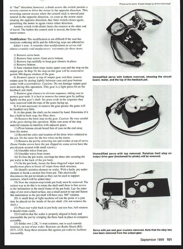
- Remove top carefully; keep gear clusters in place.
- Remove bottom.
- Note rotation-limit stops inside upper case on output gear. (The stop gear will be removed to permit 360-degree rotation of the gear.)
- Remove spacer on top of output gear; remove output gear by prying lightly between the case and gear with a small screwdriver. Caution: do not damage output gear teeth. During operation the output gear is a light press fit on the feedback pot shaft.
- Remove gear clusters in the obvious sequence, taking care to protect gear teeth. It is best to remove the center gear by pulling lightly on the gear shaft. Set gears aside in the sequence removed.
- It is not necessary to remove the gear grease; the gears will be handled very little.
- At this point, the shaft can be rotated by hand. Determine if it has a built-in limit stop; the Hitec does.
- Remove the limit stop on the gear. Caution: Be very careful of the gears during this operation. Make sure none of the stop material remains to interfere with adjacent gears.
- Pivot bottom circuit board free of case on the end away from the motor.
- Record the color and location of the three wires soldered to the pot. Do the same for the two wires on the motor.
- Remove the pot by removing nut and washer at top of servo. (Some Futaba servos have the pot clipped in; some servos have the pot element secured with small screws.)
- Unsolder wires from pot.
- Unsolder wires from motor.
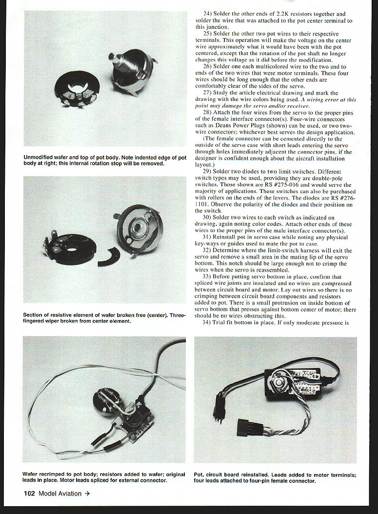
- To free the pot wafer, uncrimp the three tabs securing the pot wafer to the back of the pot body.
- On the pot body, locate the three-fingered wiper and use needle-nose pliers to break off wiper from shaft structure.
- Identify resistive element on wafer. With a knife, pry under element to break a section free from pot. This electrically disconnects the pot terminals so they can be used to support resistors, which will be added later.
- Now the rotation-stop inside pot body must be removed. The easiest way to do this is to rotate the shaft until there is free access to the indentation in the metal frame of the pot body. Lay the outer edge of pot over a hard surface, use a small punch to tap and flatten this indentation so the pot shaft will have easy 360-degree rotation.
- A small drop of light machine oil (on the point of a pin) may be placed on the inside of the pot shaft. (Do not remove the shaft.)
- Place wafer back in pot body and test free, full rotation. It should rotate easily.
- Confirm that the wafer is properly aligned in body and reassemble the pot by crimping the three tabs in place to compress assembly.
- Solder two 2.2K, 1/4-watt resistors, one to each outside terminal on rear of pot wafer. Resistors are Radio Shack (RS) #271-1325. Keep these resistors flat against pot wafer to facilitate reassembly.
- Solder the other ends of the two 2.2K resistors together and solder the wire that was attached to the pot center terminal to this junction.
- Solder the other two pot wires to their respective terminals. This operation will make the voltage on the center wire approximately what it would have been with the pot centered, ensuring that rotation of the pot shaft no longer changes this voltage as it did before the modification.
- Solder one multicolored wire to each of the two motor terminal wires. These four wires should be long enough that the other ends are comfortably clear of the sides of the servo.
- Study the article electrical drawing and mark the drawing with the wire colors being used. A wiring error at this point may damage the servo and/or receiver.
- Attach the four wires from the servo to the proper pins of the female interface connector(s). Four-wire connectors such as Deans Power Plugs can be used, or two- to three-wire connectors; whichever best serves the design application. (The female connector can be cemented directly to the outside of the servo case with short leads entering the servo through holes immediately adjacent the connector pins, if the designer is confident about the aircraft installation layout.)
- Solder two diodes to two limit switches. Different switch types may be used, providing they are double-throw switches. Those shown are RS #275-016 and would serve the majority of applications. These switches can also be purchased with rollers on the ends of the levers. The diodes are RS #276-1101. Observe the polarity of the diodes and their position on the switch.
- Solder two wires to each switch as indicated on the drawing, again noting color codes. Attach other ends of these wires to the proper pins of the male interface connector(s).
- Reinstall pot in servo case while noting any physical keyways or guides used to mate the pot to case.
- Determine where the limit-switch harness will exit the servo and remove a small area in the mating lip of the servo bottom. This notch should be large enough not to crimp the wires when the servo is reassembled.
- Before putting servo bottom in place, confirm that spliced wire joints are insulated and no wires are compressed between circuit board and motor. Lay out wires so there is no crimping between circuit board components and resistors added to pot. There is a small protrusion on inside bottom of servo that presses against bottom center of motor; there should be no wires obstructing this.
- Trial fit bottom in place. If only moderate pressure is necessary to get a good fit at servo sides and bottom, install four screws. If this fit is not as it was before disassembly, remove bottom, determine area of resistance, and reposition wires. (Now is not the time for impatience. It will fit perfectly with only a little pressure when the wires are positioned properly.)
- Reinstall gear clusters in the reverse order they were removed.
- Inspect gear clusters to confirm they are free of any debris and all teeth faces are in proper alignment.
- Press servo top cover in place. There should be no resistance in achieving the proper fit.
- Secure four screws holding servo together.
Testing
A servo analyzer is useful for testing. Plug the modified servo into a receiver channel that has mechanical centering on the transmitter, such as the rudder. Apply power to receiver and transmitter. The stick can be moved both directions, with the servo output changing directions. A small amount of stick movement will result in slow rotation.
While holding stick at one extreme position, press each switch to determine which switch stops the rotation. When servo stops rotating, continue to hold the limit switch and reverse direction with control stick. As the stick passes neutral, the motor will start to rotate. Test both limit switches in this manner.
With control stick at neutral, the servo should not rotate. If it does, position trim to stop rotation.
Conclusion
In the early days of radio control, servos were made from discrete components and a timing capacitor and resistor were replaced on the circuit board to broaden the null point, making the neutral area wider.
With the SMT (Surface Mount Technology) used in modern servos, replacing these components is no longer an easy option; however, many transmitters have exponential stick adjustment, which accomplishes the same thing.
Using an old "standard" transmitter and receiver, this modified servo had a positive and stable (though narrow) neutral.
The applications of the "360° servo" are many. It will take some time before the designer will stop thinking in just ±45° terms; only then will the full potential of powerful, airborne bidirectional, variable-speed DC motors be fully realized.
— Ken Cashion 157 Tennyson Cove Picayune, MS 39466 E-mail: [email protected]
Transcribed from original scans by AI. Minor OCR errors may remain.

