
Airborne KJ-1
Ken Johnson
Model builders certainly value the air that keeps our wondrous little machines aloft for so long. Indeed, the air and what happens to it are of great value to us. The moving air or wind causes wondrous things to happen; every kite flier will attest to this. As Free Flight modelers, we are also aware of what the movement in the air can do.
Now there is an additional use for air: as a propellant for the airplane.
A couple of years ago a Free Flight airplane called the Air Hog™ came out on the market, powered by an ingenious little plastic motor. The Air Hog™ is supplied with an air pump to put stored air into a plastic air bladder, which is released into the engine as the propeller is spun. A short video explaining how to trim and fly the Air Hog™ is also supplied. I know many, many kids of all ages who have truly enjoyed this "toy" airplane, using it as it comes from the box.
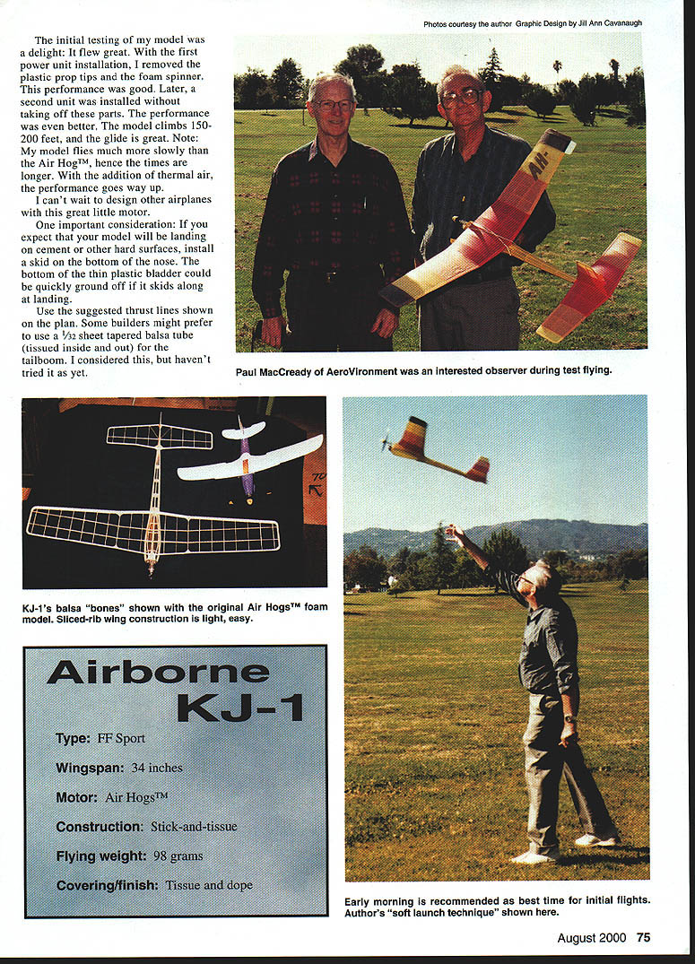
Many modelers have seen the potential in the power unit, for application in their own designs for stick-and-tissue model airplanes. I stripped the motor down to bare bones and it weighed 50 grams. Testing revealed the run time to be approximately one minute from a full pump-up. The torque output is adequate for a larger airframe than the one used in the Air Hog™.
I set about designing my own model for the Air Hog™ power unit. The result was a 34-inch-span airplane with an eight-inch root wing chord. The ready-to-fly weight of my airplane is 98 grams, compared with 88 grams for the "stock" Air Hog™. The area of the stabilizer on my version is approximately the same as the Air Hog™'s wing area.
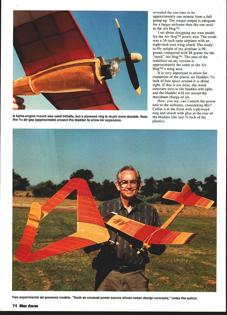
It is very important to allow for expansion of the plastic air bladder; 3/16 inch of free space around it is about right. If this is not done, the wood structure next to the bladder will split, and the bladder will not accept the maximum charge of air.
How, you say, can I attach the power unit to the airframe, considering this? Collar it at the front with a plywood ring and attach with glue at the rear of the bladder (the last 5/8 inch of the plastic).
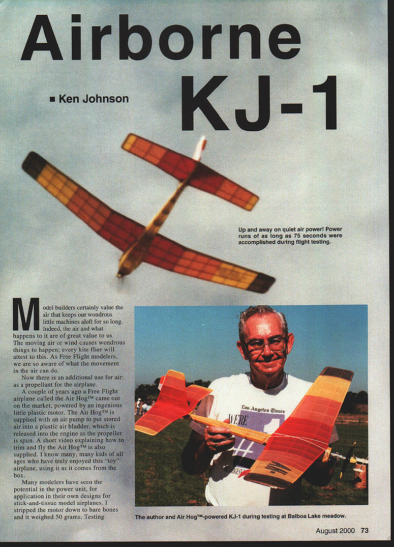
The initial testing of my model was a delight: it flew great. With the first power unit installation, I removed the plastic prop tips and the foam spinner. This performance was good. Later, a second unit was installed without taking off these parts. The performance was even better. The model climbs 150–200 feet, and the glide is great. Note: my model flies much more slowly than the Air Hog™, hence the times are longer. With the addition of the thermal air, the performance goes way up.
I can't wait to design other airplanes with this great little motor.
One important consideration: if you expect that your model will be landing on cement or other hard surfaces, install a skid on the bottom of the nose. The bottom of the thin plastic bladder could be quickly ground off if it skids along at landing.
Use the suggested thrust lines shown on the plan. Some builders might prefer to use a 1/32 sheet tapered balsa tube (tissued inside and out) for the tailboom. I considered this, but haven't tried it as yet.
Specifications
- Airborne KJ-1
- Type: FF Sport
- Wingspan: 34 inches
- Motor: Air Hog™
- Construction: Stick-and-tissue
- Flying weight: 98 grams
- Covering/finish: Tissue and dope
The model can be built lighter; by using laminated and rounded balsa outlines, it might be possible to cut off another five grams of weight.
It is necessary to remove the plastic clamp at the top of the air pump. I did this by sawing off the two arms flush and cementing a small rectangular piece of foam plastic over this area. It is now necessary to hold the airplane's rear fuselage with your left hand to steady it as you pump with the right hand. Don't forget the Velcro™ clamp that goes over the black top of the air bladder at the front. This prevents the nozzle from being disconnected from the pump while pumping in the air supply.
CONSTRUCTION
Fuselage
This is a horizontal keel with half-round formers attached top and bottom.
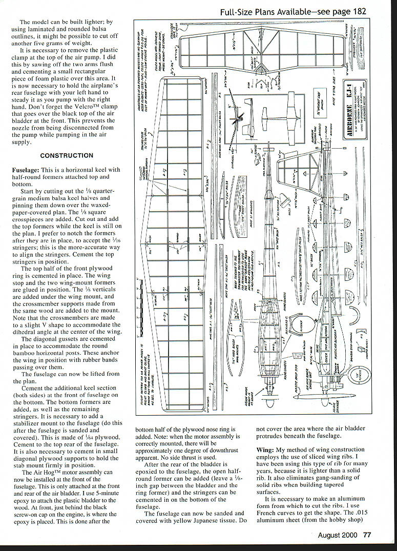
Start by cutting out the 1/8" quarter-grain medium balsa keel halves and pinning them down over the waxed-paper-covered plan. The 1/8" square crosspieces are added. Cut out and add the top formers while the keel is still on the plan. I prefer to notch the formers after they are in place, to accept the 1/16" stringers; this is the more-accurate way to align the stringers. Cement the top stringers in position.
The top half of the front plywood ring is cemented in place. The wing stop and the two wing-mount formers are glued in position. The 1/8" verticals are added under the wing mount, and the crossmember supports made from the same wood are added to the mount. Note that the crossmembers are made to a slight V shape to accommodate the dihedral angle at the center of the wing.
The diagonal gussets are cemented in place to accommodate the round bamboo horizontal posts. These anchor the wing in position with rubber bands passing over them.
The fuselage can now be lifted from the plan.
Cement the additional keel section (both sides) at the front of fuselage on the bottom. The bottom formers are added, as well as the remaining stringers. It is necessary to add a stabilizer mount to the fuselage (do this after the fuselage is sanded and covered). This is made of 1/64" plywood. Cement to the top rear of the fuselage. It is also necessary to cement in small diagonal plywood supports to hold the stab mount firmly in position.
The Air Hog™ motor assembly can now be installed at the front of the fuselage. This is only attached at the front and rear of the air bladder. I use 5-minute epoxy to attach the plastic bladder to the wood. At front, just behind the black screw-on cap on the engine, is where the epoxy is placed. This is done after the bottom half of the plywood nose ring is added. Note: when the motor assembly is correctly mounted, there will be approximately one degree of downthrust apparent. No side thrust is used.
After the rear of the bladder is epoxied to the fuselage, the open half-round former can be added (leave a 1/8" gap between the bladder and the rear former) and the stringers can be cemented in on the bottom of the fuselage.
The fuselage can now be sanded and covered with yellow Japanese tissue. Do not cover the area where the air bladder protrudes beneath the fuselage.
Wing
My method of wing construction employs the use of sliced wing ribs. I have been using this type of rib for many years, because it is lighter than a solid rib. It also eliminates gang-sanding of solid ribs when building tapered surfaces.
It is necessary to make an aluminum form from which to cut the ribs. I use French curves to get the shape. The .015" aluminum sheet (from the hobby shop) can be cut with scissors to the correct arc, then filed smooth.
Pin down the leading and trailing edges, plus the tips. Then cement in the 1/16" square under-ribs. Add the front and rear spars, on edge. The top ribs are attached at the leading edge of the wing, one by one, and then are trimmed and cemented to the front of the trailing edge. Then the ribs are glued to the spars front and rear.
The dihedral at center is 3/4" and 4 5/8" at the tips. Remember to cement the 1/16" plywood dihedral keepers (supports) on either side of the spars at each dihedral break. I place straight pins up tight against the keepers to ensure a snug fit during drying time.
Glue in the diagonal gussets and sand to a concave half-round, where shown on the plan.
Horizontal Tail
This is constructed in a manner similar to the wing, by using sliced ribs and a thin vertical spar.
The leading edge, trailing edge, and tips are pinned down over the plan. The 1/16" square under-ribs are cut and cemented in position. The spar is cut to shape and cemented to the 1/16" under-ribs.
As with the wing, the upper ribs are cut with the template and cemented to the leading edge, then cut and cemented to the trailing edge. Then the ribs are attached to the spar. Add the diagonal gussets at the leading edge.
Bend the dihedralizer (DT) wire saddle and cement to the diagonal gussets. Add the round bamboo extension to the rear center of the stabilizer. Make sure this bamboo is on a horizontal line to the fuselage. The bamboo is sold in grocery stores as barbecue skewers, and is shaved and sanded to the round shape.
Vertical Fin
This is built last, and is of conventional construction. Note that the bottom horizontal is the same curve as the top arc on the stabilizer. I attached a trim tab to the trailing edge of the fin for turn trim.
Covering/Finish
Cover the model with Japanese tissue. Mine was red, orange, yellow, and black. I covered the model with the tissue dry, using nitrate dope to attach the tissue. Then I lightly watershrank and doped the tissue with a thinned coat of nitrate dope.
The completed model should weigh 95 grams. Check for warps and correct if noticed.
Flying
My model flew right off the board. A slight stall was observed, and was corrected by shimming the stab. A right climb is ideal, because the strong torque will tend to make it spin to the left. I added a trim tab to the trailing edge of the right outer wing panel, bending it down to hold the wing level in the right climb.
After a few test flights you will learn that the model can stand a rather hefty launch without stalling. And I discovered that it can be launched without spinning the propeller sometimes. The air pressure over the blades is enough to start the air engine in flight.
Be careful when pumping up the bladder. The tail must be held in position with the non-pumping hand, to keep a snug fit on the filling nozzle. Mine usually requires 40 to 50 pumps for maximum charge. I recommend a lesser charge at first, to check the flight path and glide trim of the airplane.
My thanks to the people at Spinnmaster Toy Company for allowing use of their name and their product for this article. I hope that many modelers will try this new and exciting power source. It's clean, inexpensive and fun to build and fly. And the price of the fuel: 0!
I'm now at work on my fourth Air Hog™-powered model. It is infectious, this new thing!
MA
Ken Johnson <REDACTED>
Transcribed from original scans by AI. Minor OCR errors may remain.

