
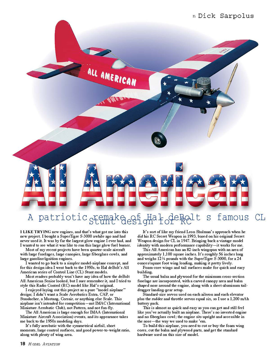
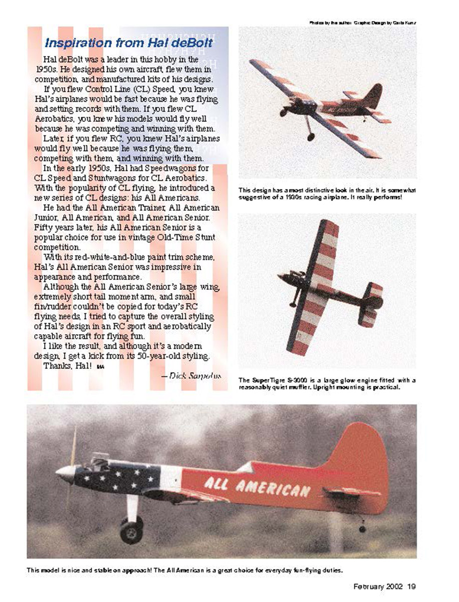
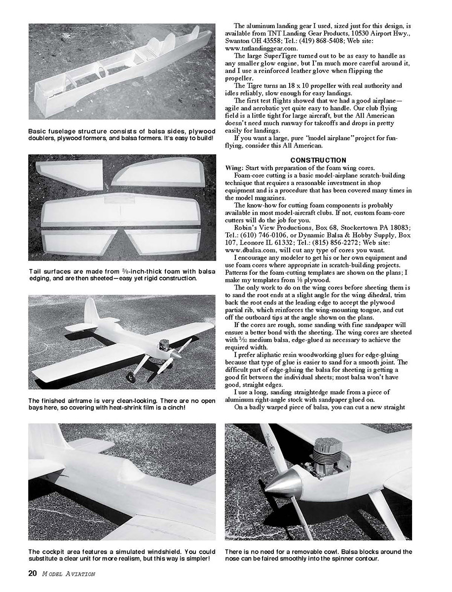
All American
A patriotic remake of Hal deBolt's famous CL Stunt design for RC
I LIKE TRYING new engines, and that's what got me into this new project. I bought a SuperTigre S-3000 awhile ago and had never used it. It was by far the largest glow engine I ever had, and I wanted to see what it was like to run this large glow fuel burner.
Most of my recent projects have been quarter-scale aircraft with large fuselages, large canopies, large fiberglass cowls, and large gasoline/ignition engines.
I wanted to go back to a simpler model-airplane concept, and for this design idea I went back to the 1950s, to Hal deBolt's All American series of Control Line (CL) Stunt models.
Most readers probably won't have any idea of how the deBolt All American Senior looked, but I sure remember it, and I tried to style this Radio Control (RC) model like Hal's original.
I enjoyed laying out this project as a pure "model airplane" design; I didn't want a Scale Aerobatics Extra, CAP, or Staudacher, a Mustang, Corsair, or anything else Scale. This airplane isn't intended for competition—not IMAC (International Miniature Aerobatic Club), not Pattern, and not fun-fly.
The All American is large enough for IMAA (International Miniature Aircraft Association) events, and its appearance takes me back to the 1950s modeling days.
It's fully aerobatic with the symmetrical airfoil, short moments, large control surfaces, and good power-to-weight ratio, along with plenty of wing area.
It's sort of like my friend Leon Shulman's approach when he did his RC Secret Weapon in 1993, based on his original Secret Weapon design for CL in 1947. Bringing back a vintage model identity with modern performance capability—it works for me.
This All American has an 82-inch wingspan with an area of approximately 1,100 square inches. It's roughly 56 inches long and weighs 12 1/4 pounds with the SuperTigre S-3000, for a 24 ounces/square foot wing loading, making it pretty lively.
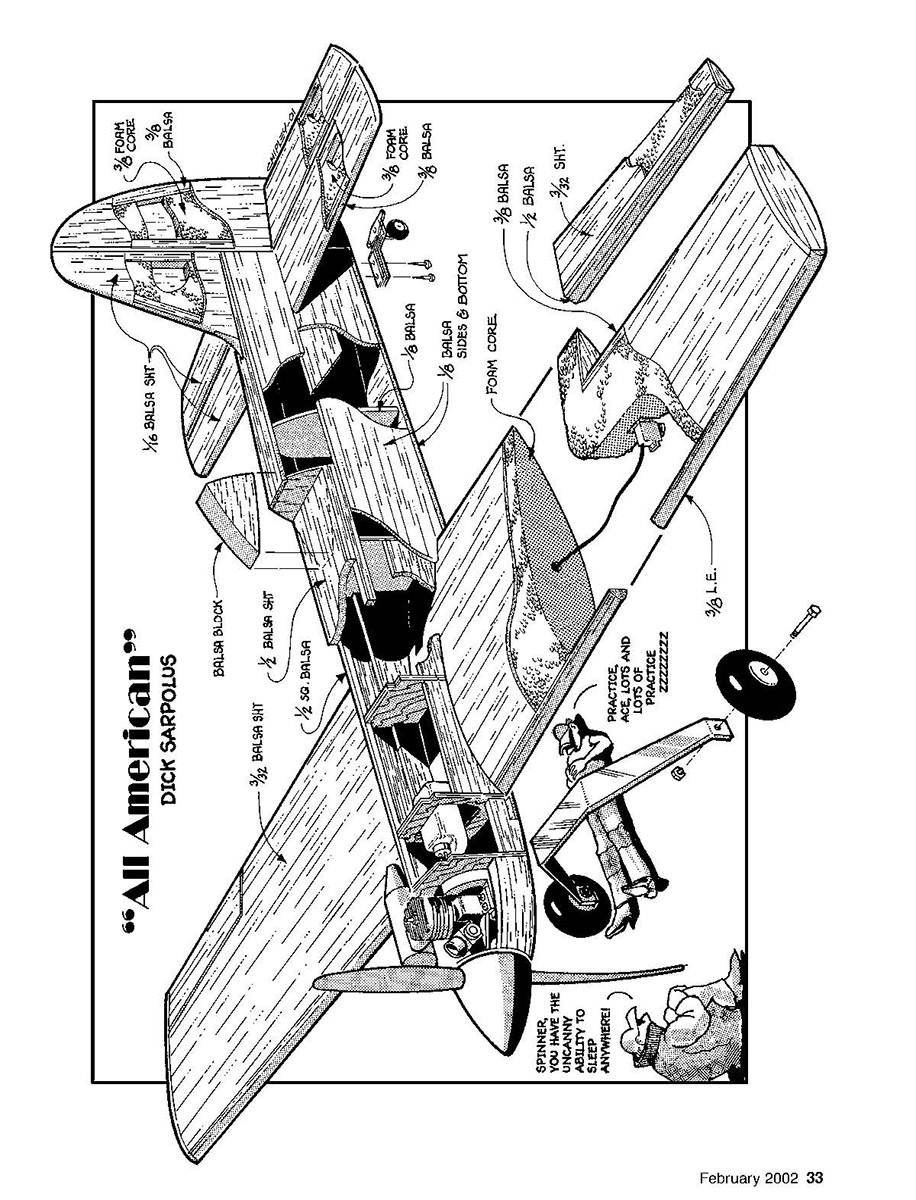
Foam-core wings and tail surfaces make for quick and easy building.
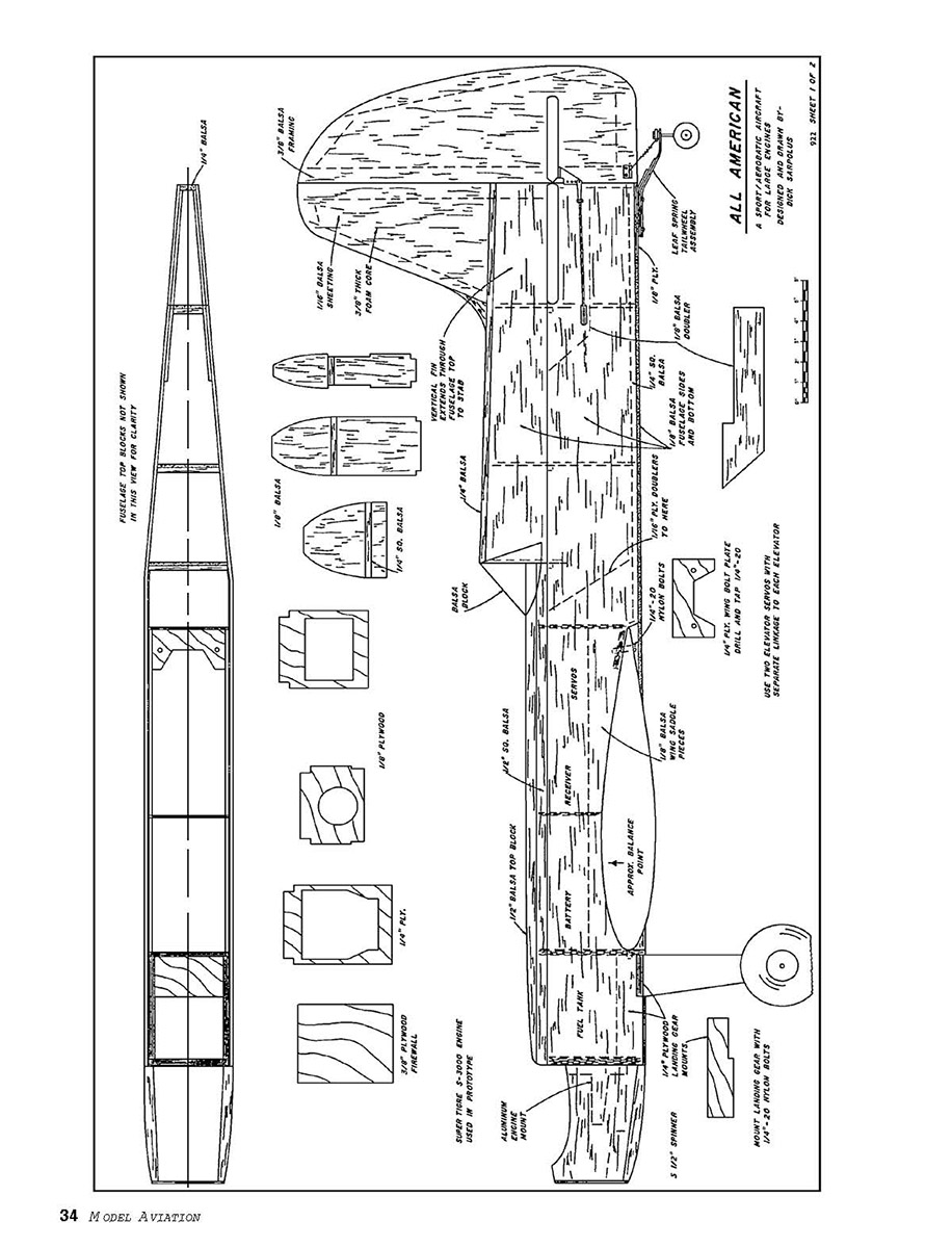
The usual balsa and plywood for the minimum cross-section fuselage are incorporated, with a carved canopy area and balsa shaped nose around the engine, along with a sheet-aluminum taildragger landing-gear setup.
Standard-size servos used on each aileron and each elevator runs the rudder and throttle servos equal six, so I use a 1,200 mAh battery pack.
This is almost as quick and easy as you can get and still feel like you've actually built an airplane. There's no inverted engine and no fiberglass cowl; the engine sits upright and accessible in the nose—the way we used to make 'em.
To build this airplane, you need to cut or buy the foam wing cores, cut the balsa and plywood parts, and get the standard hardware used on this size of model.
No continuation of the primary article "All American" appears on this scanned page.
CONSTRUCTION
Wing: Start with preparation of the foam wing cores.
Foam-core cutting is a basic model-airplane scratch-building technique that requires a reasonable investment in shop equipment and is a procedure that has been covered many times in the model magazines.
The know-how for cutting foam components is probably available in most model-aircraft clubs. If not, custom foam-core cutters will do the job for you.
Robin's View Productions, Box 68, Stockertown PA 18083; Tel.: (610) 746-0106, or Dynamic Balsa & Hobby Supply, Box 107, Lenore IL 61332; Tel.: (815) 856-2272; Web site: www.dbalsa.com, will cut any type of cores you want.
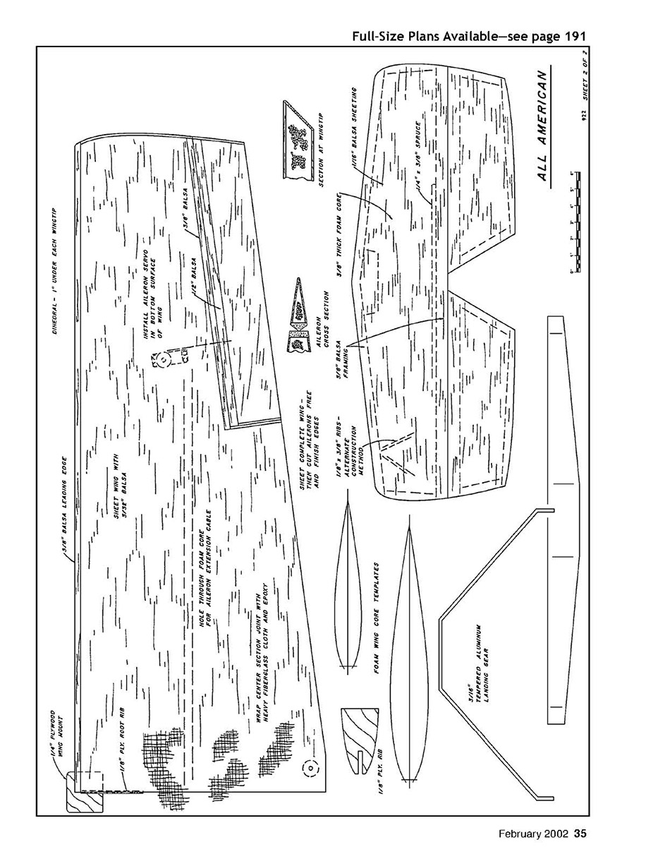
I encourage any modeler to get his or her own equipment and use foam cores where appropriate in scratch-building projects. Patterns for the foam-cutting templates are shown on the plans; I make my templates from 1/8 plywood.
The only work to do on the wing cores before sheeting them is to sand the root ends at a slight angle for the wing dihedral, trim back the root ends at the leading edge to accept the plywood partial rib, which reinforces the wing-mounting tongue, and cut off the outboard tips at the angle shown on the plans.
If the cores are rough, some sanding with fine sandpaper will ensure a better bond with the sheeting. The wing cores are sheeted with 3/32 medium balsa, edge-glued as necessary to achieve the required width.
I prefer aliphatic resin woodworking glues for edge-gluing because that type of glue is easier to sand for a smooth joint. The difficult part of edge-gluing the balsa for sheeting is getting a good fit between the individual sheets; most balsa won't have good, straight edges.
I use a long, sanding straightedge made from a piece of aluminum right-angle stock with sandpaper glued on.
On a badly warped piece of balsa, you can cut a new straight the angle-cut core, and sheet that section with 3/32 balsa, then trim and sand the edges of the tip.
Cut the ailerons free from the sheeting, wing panels, and trim them to allow for the balsa edging on the wing panels and the ailerons, which is epoxy-glued in place and planed and sanded to shape.
Hinge the ailerons along their centerlines using large, sturdy, free-moving hinges of the type you prefer. Keep the gap between the ailerons and the wing as tight as possible while still permitting full aileron movement. Don't glue the hinges in place yet; that will be done later, after the covering has been applied.
Cut recesses into the bottom wing surface for the aileron servo mounting. Epoxy plywood mounting pieces in position in the wings to situate your servos; have the servos protrude from the wing surface just far enough for hookup of the aileron pushrods.
I used to bury the aileron servos completely inside the wing with removable hatches for access, but it's much easier to leave them exposed.
A hole, or "tunnel," is needed through the foam cores from the root to the aileron-servo location for the servo extension cable.
To melt the tunnel, I heat the end of a piece of metal rod with a propane torch and push the hot end through the foam; I hope your aim is good.
An alternative method is to cut a groove in the foam-core surface before the sheeting is applied.
Where the wing hold-down bolt will be located, insert dowel sections or hardwood blocks flush with the sheeted wing panels before the fiberglass cloth and epoxy is added.
Block up the tips of the wing panels to join the wing at the proper dihedral. I use roughly one inch under each tip.
Butt the wing halves together, then wrap the center joint of the wing with heavy fiberglass cloth and epoxy. I used a 10-inch-wide strip of cloth around the wing.
I brush on a coat of epoxy, position the fiberglass cloth, and brush on additional epoxy to make sure the cloth is saturated.
For a good, smooth appearance without too much sanding or extra weight, I squeeze a little more epoxy, leaving enough so that the cloth is saturated for strength but is smooth and level.
The plywood wing mounting tab is used at the leading-edge position and retains the wing. Cut through the fiberglass cloth to add the plywood tab, or install it first then cut the cloth as you apply it—whichever you prefer.
With the mounting tab in the wing, the
Styrofoam® with 3/8" balsa framing added before sheeting the surfaces with 1/16" balsa, just as with the wing foam cores.
Round the leading and trailing edges of the tail surfaces, bevel the elevator and rudder leading edges, and cut the slots or drill the holes along the centerlines of the surfaces for whatever hinge type you're using.
Notch the control surfaces as required to permit a close fit of the surfaces to the main structures, allowing proper movement. Don't glue the hinges in place at this time; you'll do that after covering.
I use 1/8" plywood pads for control-horn mounting, recessing and epoxying the plywood into the elevators and rudder. The heavy-duty nylon horns are mounted with self-tapping screws.
Final Assembly: I mount the wing to the fuselage, adjusting the fit of the wing-mounting tab through the fuselage bulkhead if necessary, and drill and tap the wing mount for the 1/4-20 nylon bolts that hold the wing in place.
With the wing mounted, I add the horizontal stabilizer and align it with the wing. Then I add the vertical fin perpendicular to the stabilizer.
The two elevator pushrods cross inside the fuselage so they can be
Transcribed from original scans by AI. Minor OCR errors may remain.

