
Altair
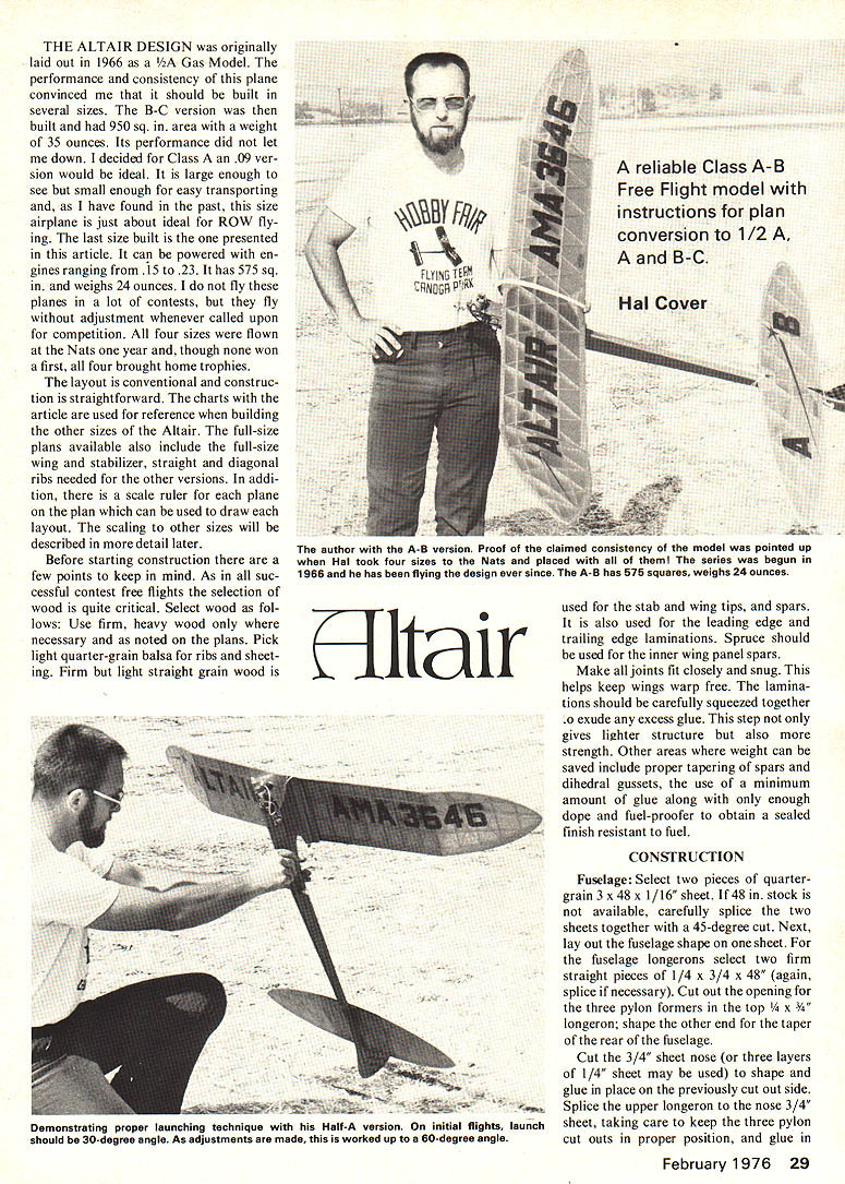
THE ALTAIR DESIGN was originally laid out in 1966 as a 1/2A Gas Model. The performance and consistency of this plane convinced me that it should be built in several sizes. The B-C version was then built and had 950 sq. in. area with a weight of 35 ounces. Its performance did not let me down. I decided for Class A an .09 version would be ideal. It is large enough to see but small enough for easy transporting and, as I have found in the past, this size airplane is just about ideal for ROW flying. The last size built is the one presented in this article. It can be powered with engines ranging from .15 to .23. It has 575 sq. in. and weighs 24 ounces. I do not fly these planes in a lot of contests, but they fly without adjustment whenever called upon for competition. All four sizes were flown at the Nats one year and, though none won a first, all four brought home trophies.
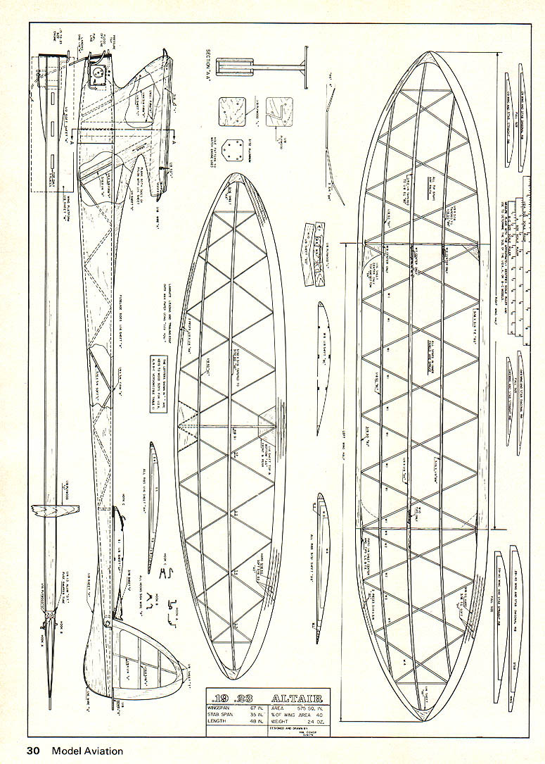
The layout is conventional and construction is straightforward. The charts with the article are used for reference when building the other sizes of the Altair. The full-size plans available also include the full-size wing and stabilizer, straight and diagonal ribs needed for the other versions. In addition, there is a scale ruler for each plane on the plan which can be used to draw each layout. The scaling to other sizes will be described in more detail later.
Before starting construction there are a few points to keep in mind. As in all successful contest free flights the selection of wood is quite critical. Select wood as follows: Use firm, heavy wood only where necessary and as noted on the plans. Pick light quarter-grain balsa for ribs and sheeting. Firm but light straight grain wood is used for the stab and wing tips, and spars. It is also used for the leading edge and trailing edge laminations. Spruce should be used for the inner wing panel spars.
Make all joints fit closely and snug. This helps keep wings warp free. The laminations should be carefully squeezed together to exude any excess glue. This step not only gives lighter structure but also more strength. Other areas where weight can be saved include proper tapering of spars and dihedral gussets, the use of a minimum amount of glue along with only enough dope and fuel-proofer to obtain a sealed finish resistant to fuel.
CONSTRUCTION
Fuselage: Select two pieces of quarter-grain 3 x 48 x 1/16" sheet. If 48 in. stock is not available, carefully splice the two sheets together with a 45-degree cut. Next, lay out the fuselage shape on one sheet. For the fuselage longerons select two firm straight pieces of 1/4 x 3/4 x 48" (again, splice if necessary). Cut out the opening for the three pylon formers in the top 1/4 x 3/4" longeron; shape the other end for the taper of the rear of the fuselage.
Cut the 3/4" sheet nose (or three layers of 1/4" sheet may be used) to shape and glue in place on the previously cut out side. Splice the upper longeron to the nose 3/4" sheet, taking care to keep the three pylon cutouts in proper position, and glue in place. Add 3/16 x 1/4" diagonals to the position of the three pylon formers in the center fuselage and add three pieces to form the basic pylon structure. Use hard 1/4 x 3/4" and 1/4 x 1/4" to make sure the three lie in the same plane parallel to the fuselage sides. Dry. Add other 3/16 x 1/4" diagonals to complete pylon construction inside the fuselage. Add light straight grain 3/16 x 3/4" diagonals down the entire length of the fuselage as shown. Parts dry, sand surface flat and glue second side in place. Trim off excess sheet and sand nose to match thrust angles shown on plans.
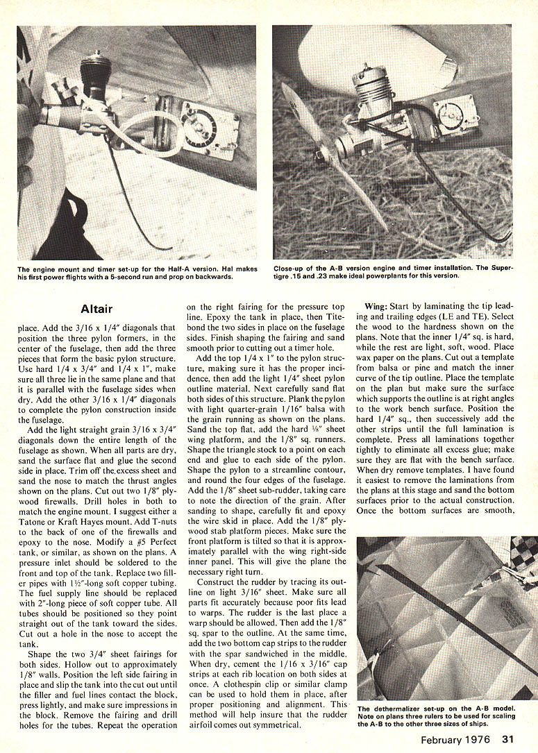
Cut out two 1/8" plywood firewalls. Drill holes in both to match engine mount (suggest either Tatone, Kraft or Hayes mount). Add I-nuts to the back firewalls and epoxy to the nose. Modify fuel tank similar to that shown on plans. The pressure inlet should be soldered into the front top of the tank. Replace the two filler pipes with 2" long soft copper tubing. The fuel supply line should be a 2" long piece of soft copper tube. Tubes should be positioned pointing straight out of the tank toward the sides. Cut out hole in nose to accept tank.
Shape two 3/4" sheet fairings for both sides. Hollow out approximately 1/8" walls. Position left side fairing, place slip tank cutout until filler fuel lines contact the block; press lightly and make sure impressions are in the block. Remove fairing and drill the holes for the tubes. Repeat operation for the right fairing. Epoxy tank in place. Tite-bond the two sides in place with the fuselage sides. Finish shaping fairings and sand smooth prior to cutting out timer hole. Add top 1/4 x 1" pylon structure making sure it has proper incidence; add light 1/4" sheet pylon outline material. Next, carefully sand flat both sides of the structure. Add 3/16" x 1/4" diagonals. Position three pylon formers in the center of the fuselage and add three pieces to form the basic pylon structure. Use hard 1/4" x 3/4" and 1/4" x 1" stock. Make sure the three lie in the same plane parallel to the fuselage sides; dry.
Add the other 3/16" x 1/4" diagonals to complete the pylon construction inside the fuselage. Add light, straight-grain 3/16" x 3/4" diagonals down the entire length of the fuselage as shown. Dry, sand the surface flat and glue the second side in place.
Trim off excess sheet and sand the nose to match the thrust angles shown on the plans. Cut out two 1/8" plywood firewalls. Drill holes in both to match the engine mount. I suggest either a Tatone or Kraft Hayes mount. Add T-nuts to the back of one of the firewalls and epoxy to the nose. Modify a #5 Perfect tank, or similar, as shown on the plans. A pressure inlet should be soldered to the front top of the tank. Replace two filler pipes with 1-1/2" long soft copper tubing. The fuel supply line should be replaced with a 2" long piece of soft copper tube. All tubes should be positioned so they point straight out of the tank toward the sides. Cut out a hole in the nose to accept the tank.
Shape the two 3/4" sheet fairings for both sides. Hollow out to approximately 1/8" walls. Position the left side fairing in place and slip the tank into the cutout until the filler and fuel lines contact the block; press lightly and make sure impressions are in the block. Remove the fairing and drill the holes for the tubes. Repeat the operation on the right fairing for the pressure top line. Epoxy the tank in place, then Tite-bond the two sides in place on the fuselage sides. Finish shaping the fairings and sand smooth prior to cutting out the timer hole.
Add the top 1/4" x 1" to the pylon structure, making sure it has the proper incidence; then add the light 1/4" sheet pylon outline material. Next, carefully sand flat both sides of this structure. Plank the pylon with light quarter-grain 1/16" balsa with the grain running as shown on the plans. Sand the top flat, add the hard 1/8" sheet wing platform and the 1/8" sq. runners. Shape the triangle stock to a point on each end and glue to each side of the pylon. Shape the pylon to a streamline contour and round the four edges of the fuselage. Add the 1/8" sheet sub-rudder, taking care to note the direction of the grain. After sanding to shape, carefully fit and epoxy the wire skid in place. Add the 1/8" plywood skid platform pieces. Make sure the front platform is tilted so that it is approximately parallel with the wing right-side inner panel. This will give the plane the necessary right turn.
Construct the rudder by tracing its outline on light 3/16" sheet. Make sure all parts fit accurately because poor fits lead to warps. The rudder is the last place a warp should be allowed. Then add the 1/8" sq. spar to the outline. At the same time, add the two bottom cap strips to the rudder with the spar sandwiched in the middle. When dry, cement the 1/16" x 3/16" cap strips at each rib location on both sides at once. A clothespin clip or similar clamp can be used to hold them in place after proper positioning and alignment. This method will help insure that the rudder airfoil comes out symmetrical.
Wing: Start by laminating the tip leading and trailing edges (LE and TE). Select the wood to the hardness shown on the plans. Note that the inner 1/4" sq. is hard, while the rest are light, soft wood. Place wax paper on the plans. Cut out a template from balsa or pine and match the inner curve of the tip outline. Place the template on the plan but make sure the surface which supports the outline is at right angles to the work bench surface. Position the hard 1/4" sq., then successively add the other strips until the full lamination is complete. Press all laminations together tightly to eliminate all excess glue; make sure they are flat with the bench surface. When dry remove templates. I have found it easiest to remove the laminations from the plans at this stage and sand the bottom surfaces prior to the actual construction. Once the bottom surfaces are smooth,
Altair
pin in place on the plans and cut out and fit the 1/4" sheet top filler.
Select light quarter-grain 1/16" sheet for the ribs and cut out the required number. Before gluing ribs in place note the "W" pattern of the sole ribs; these are not cut or notched and should be glued in place first. When these ribs are dry, cut the other half of the ribs at the appropriate place and glue in position. This will complete the geodetic rib structure. When thoroughly dry, remove from the plans and build the other tip and inner panel in the same manner.
The next operation is to add the dihedral. By using a sanding block and a straight, flat edge of a bench or board, sand the proper angle into the tips and inner panel LE and TE. Glue together using Titebond and add the hard 1/4" sheet dihedral brace to these joints, but make sure to taper these pieces prior to installation. Assemble the other tip in the same manner. When these are dry, sand the correct angle into the center joint and assemble the center section including the dihedral braces.
Now add the center and tip dihedral break ribs. The spars are then added as follows: mark the spar location on each of three dihedral break ribs. Place a straight mortise on one panel. Align the marks with the straight edge and notch 1/8" deep; repeat the operation on the other side of the spar. Cut across the rib between the notches and remove the notch material. Repeat this operation for all other top and bottom spars in the inner panels. Glue the bottom spruce spars into the inner panels first. When dry, notch out the center dihedral break and adjacent diagonal rib as required for the dihedral gussets W, 7, 8, 9.
Make the tapered balsa tip spars and position temporarily as shown on the wing using pins. Notch 1/8" deep on both sides of the spar and cut across to remove the notch wood. Glue the lower tip spars in place and notch out the tip dihedral break rib for the dihedral gusset. Glue the tip and center section dihedral braces in place. Make sure they are the correct height so the inner surface of the top spar fits snug against the gusset and the top is flush with the top of the rib contour. The top spars may now be added along with the LE and TE dihedral break gussets and the center section sheeting. Shape the LE and TE and sand all surfaces smooth. Carefully inspect all glue joints and add additional glue as needed. Check and shape the rib airfoil contour as needed.
Stab: As you can see the stabilizer is built essentially the same as the wing. Special care should be taken in the selection of light woods for a little extra weight in the stab means a lot in the nose to offset it. All outlines are designed around 36"-long stock balsa, so no splicing should be necessary. With such long laminated pieces it is definitely easier to pre-sand the bottom after lamination and before assembly. Again, careful fitting of all pieces will give a warp-free stab. After all ribs, spars, and sheeting have been added, carefully contour the LE and TE to the airfoil shown on the plans. Make sure to maintain the rounded entry of the leading edge because this affects flight characteristics.
Miscellaneous:
Cut out the opening for the timer and bend the fuel line forward as shown on the plans. Form the landing skid to match the firewall cut out. The skid should be approximately 5 in. long with a gentle sweep backwards. Check all joints and make sure everything is sanded smooth. Bend and install the wing hooks in the pylon using epoxy. For strength and wear resistance, fiberglass cloth and resin is added to various areas. These include 1) two layers of cloth and resin on the nose, 2) one layer around the front and rear wing hook, 3) on the leading and trailing edge of the wing, 4) on the fuselage tail skid and 5) on the leading edge of the stabilizer. Another important area is around the fuel tank pipes and timer cut out. This keeps fuel seepage to a minimum. With all these miscellaneous items taken care of you can now proceed with the covering.
A note of interest here is appropriate. All the original planes of the Altair series (built between 1966–1968) were nitrate-doped tissue covering with epoxy fuel proofer. As you probably have noticed the recent trend in free-flight covering material has been away from tissue and silk to Monokote or similar materials. A very enlightening discussion was held recently with Bill Hunter of "Satellite" fame. He has found after all his experimenting with various covering materials over the past few years that tissue or silk with nitrate dope and epoxy fuel proofer still appears best! A complete cycle in 10 years.
Back to covering: dope all surfaces with a nitrate sanding sealer. Sand all dope surfaces and apply a second coat to the fuselage, the LE, TE, and dihedral break ribs of the wing and to the LE and TE of the stab. At this point it should be noted the author covers the compound surfaces of the wing tips and stab with wet Japanese tissue. It is difficult and tricky, but avoids covering these surfaces with several strips, which still is confusing because there are no convenient straight ribs where covering strips can be overlapped. As a result it is almost a necessity to use this technique.
Just a brief description of this covering technique for those who want to brave it. Cut your tissue to roughly the shape of the tip. Mix up some 50/50 nitrate dope and thinner. Next, lay the tissue on a clean flat surface and fog on an even layer of dope with an atomizer. Make sure the tissue is thoroughly damp but not "wet-wet." Carefully lay the tissue in position on the stab or wing tip top surface. Dope the 50/50 mixture through the tissue along the dihedral break rib. Gently rub the dope through the tissue. Allow a few seconds for the mixture to soften the previously applied sanding sealer (this sticks the tissue to the rib). Now, carefully and gently pull the tissue at the tip, so it is tight and tack in place at the tip. Using the 50/50 dope brushed through the tissue, work your way out from the dihedral break rib to the tip along both the LE and TE, at the same time pulling the tissue diagonally away from the surfaces to tighten it both span- and chordwise. If the tissue starts to dry during this operation lightly re-spray with water. Also, if the tissue appears incorrectly positioned just re-dope and it can be carefully peeled up and re-positioned. The key to success is don't get the tissue too wet! This method also works quite well for covering compound curves on fuselages, pylons, and rudders. All other surfaces are covered with dry tissue and then water shrunk in the conventional manner.
Assuming you have completed the covering apply two coats of the plasticized 50/50 nitrate dope and thinner mixture. Add all desired tissue trim and follow with an additional three coats. Allow the dope to dry a couple of days before adding the fuel proofer. Check all surfaces for warps and steam out, because once you apply the epoxy fuel proofer to the surfaces, warps are next to impossible to remove. All surfaces on the Altair are flat except the right wing panel which is washed in 1/8 to 3/16 of an inch. This means, as you look at the wing from front, the trailing of the right side is lower than the leading edge. Super epoxy or equivalent material should be lightly spread on the entire fuselage, the bottom inner panels of the wing and the stabilizer. Be sure to also fuel proof the 1/8" landing gear spacer plywood firewall.
Assembly:
When installing the timer it is preferable to use machine screws and T-nuts so it will not work loose from vibration. The DT hooks on the stab and fuselage are epoxied in place with a layer of glass cloth for additional strength. The DT snuffer tube is installed, also using epoxy. Flare one end to help in the inserting of the fuse.
Install the engine and hook up the plumbing as required for pinch-off or flood-off. Attach the stab to the fuselage and make a limit string from .006 braided cable. Permanently attach it to the stab rear tie-down and wire; add a detachable hook to the other end for attaching to the right side of the fuselage DT hook.
Assemble the plane and check the balance. Double check surfaces for warps; there should be present only the 1/8 to 3/16 in. wash in the right wing.
Flying:
Carefully ground check your plane before any flying. Make sure the wing is on right and does not rock on the platform. Check to see that the stab is held firmly down. Don't use short length rubber bands to hold the DT down. Loop a 3- or 4-in. band over several times, otherwise at high speeds the stab TE will tend to lift.
Run the motor, making sure the timer works consistently and shuts off the motor cleanly. Use only propellers that have been carefully balanced and remember, don't switch propeller sizes without re-trimming the plane.
With the built-in tilt and correct center of gravity (CG) the plane should glide flat and in a wide right circle. Minor changes in balance and stab tilt may be made for glide trim but try to stay close to recommended CG and incidence angles. Put your prop on backwards and run the engine fairly fast with your timer set for 5 seconds. On initial flights the plane should be launched at about a 30° angle directly into the wind. The pattern should be a climb at about 30° and with a slight right turn tendency. What you are working for is a 60° angle climb with about 1½ to 2 turns in 15 seconds. If initial flight appears safe, put the prop on forwards and proceed. Add right or left thrust as needed to obtain the previously described climb pattern. This trimming method was used on all four sizes and, in fact, the A-B version was flown full power with a 15-second motor run by fourth flight with no further adjustments needed.
Scaling the Other Size Planes:
When you obtain the full-size plans to the A-B version all essential material is available to lay out the other sizes of the Altair. You will note the different scale rulers on the plans. These are used to scale the A-B plans to the other sizes. This is done quite easily by first cutting out the appropriate scale ruler and gluing to 1/32" plywood. Take the ruler and lay it on the plans for any dimension you need, then read the scale ruler. It will read the dimensions you will use on the planes you are laying out. For instance, you will notice the 1/2A ruler reads 7-3/8 in. when used to measure the chord of the A/B plane. That means the chord of the 1/2A is 7-3/8 in. If this is done with the B/C ruler the dimensions will read over 11 in. Other words, for the scaling of other size versions of the Altair all necessary dimensions are taken using the appropriate scale ruler and transferring them to the new plans. Then a standard ruler can be used. This method is about as straightforward as scaling systems get.
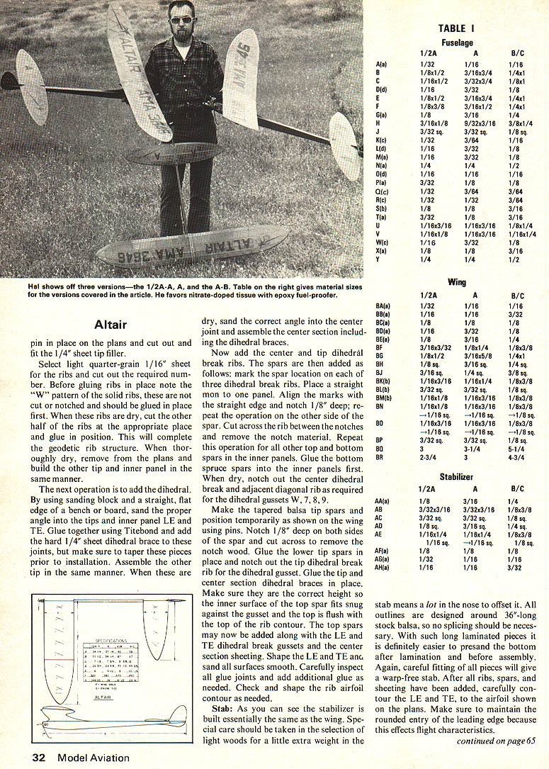
I hope you find it relatively easy to work with when scaling the other size planes. The wood sizes are coded by letter on the A/B plans and charted in Table 1 for all versions of the plane. The airfoils, both the diagonal and straight ribs, are shown full size on the A/B plans and need only be traced or glued on to plywood.
Whichever size you pick, I hope it flies as well as mine and lasts as long and, most important, gives you satisfaction in building and flying.
Transcribed from original scans by AI. Minor OCR errors may remain.

