
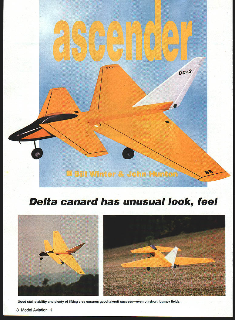
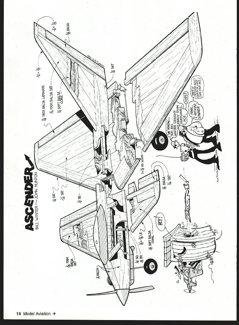
Ascender
Bill Winter & John Hunton
Delta canard has unusual look, feel
Good stall stability and plenty of lifting area ensure good takeoff success—even on short, bumpy fields.
The namesake of the Ascender is the World War II Curtiss canard experimental fighter—an exciting design that never made it to production. Understanding of tail-first design has come a long way since the unique Curtiss fighter, with the XB-70 Valkyrie, the SAAB jet fighters, and Rutan's work.
The QED model design (March 1996 Model Aviation) proved that the canard configuration had much to offer in stability without giving up anything in performance.
Bill Winter's first delta canard, the Javelin (September 1997 RC Modeler), was developed for me and the way I like to fly—fast. In becoming familiar with the superb low-speed characteristics of a delta-wing-plus-canard configuration through the Javelin, Bill designed a second delta canard for the way he flies: a model that has sport-type speed and good, solid handling characteristics.
The Ascender surpassed his goals. It has a great look and can zip with the other .40 models, yet hang in the air into a breeze, and even thermal at idle.
With a higher aspect ratio than the Javelin and squared-off tips, the Ascender may bend the definition of a delta; however, it maintains the "slotted" effect between the foreplane and the mainplane, and with its 30° swept wing, extraordinary stability, and coordinated, smooth response to control inputs about all three axes, we think the delta-canard description remains applicable.
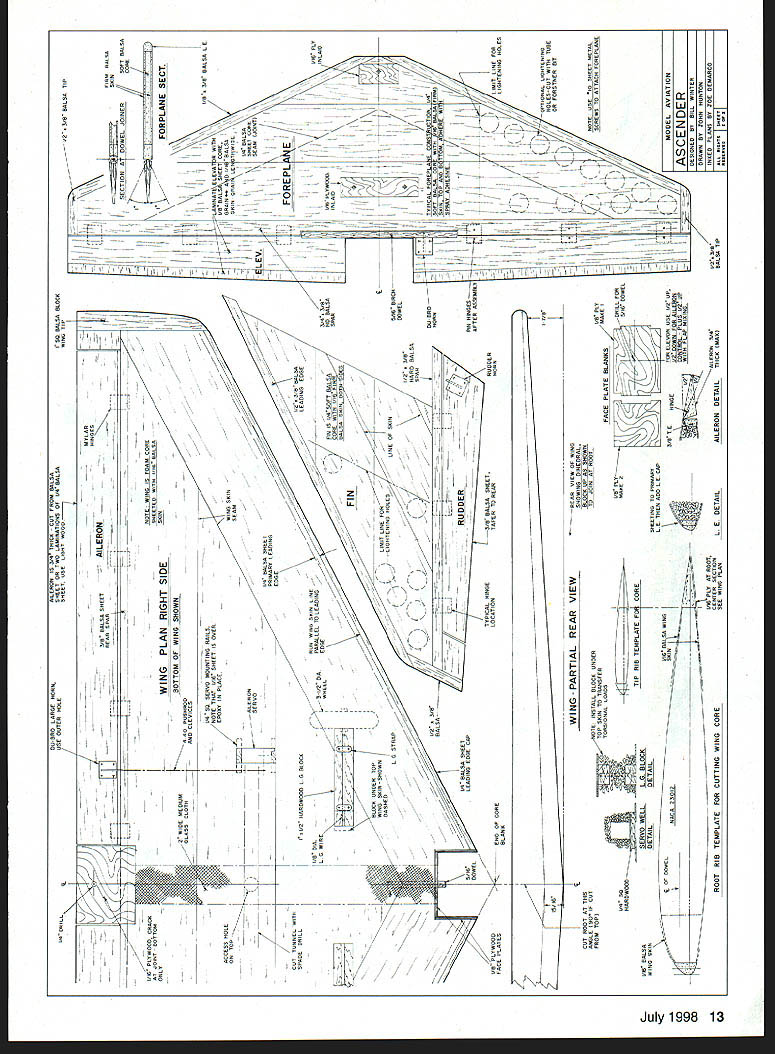
Construction
Select light-grade balsa unless otherwise stated. Sheet balsa for the wing must be able to curl easily along its length to match the airfoil and to eliminate any tendency to pull free. All blocks must be light wood. Wood sizes given on the plans are generally not mentioned in this text.
Wing:
- Make 1/16" plywood patterns of the tip and root ribs.
- The core will be cut off flat behind the inner leading edge and the front of the aileron spar (we used Evans Aircraft for both cores and double-stick lightweight tape for skinning).
The overall sequence for building the wing is:
- Attach inner leading edge and aileron spars to each core panel.
- Prepare skinning materials; make servo and landing gear cutouts; drill cable access tunnels.
- Apply the skin.
- Add root, tip, and trailing edge pieces; add tips.
- Join panels on their centerline.
- Prepare the center leading edge cutout for the fuselage.
Begin by tapering the inner leading edge strip to nearly the required shape. Make it slightly oversize for safety and sand to match the airfoil after it has been pinned and glued in place (use yellow aliphatic-resin glue). Use long straight pins for holding alignment, and wrap with short pieces of masking tape to hold alignment.
Ensure a firm joint. Sight along the wing to check that the edges are not bowed. Note that the outer leading edge is attached later, after skinning. Attach the aileron spar the same way.
Make a sanding board from a piece of plywood to which sandpaper is attached with spray adhesive. Sand the edges in repeated spanwise paths, from root to tip. Vacuum the panel thoroughly.
The following skinning method was used on the Ascender; you may prefer preassembling the four wing skins before starting. If so, allow at least 1/4" overlap along the long edges, as tolerance for minor layout errors.
With double-stick tape it is convenient to put down one skin section at a time, using an appropriate width of tape strips. All sheet pieces must be precisely trimmed to match, using a straightedge.
Begin skinning by installing two 4"-wide sheets, one overlapping the inner leading edge and the other overlapping the trailing-edge spar, grain parallel to each edge. After the servo mounting rails and landing gear blocks have been installed, fill the remaining open triangular shape with a preformed triangular skin section. Apply a thin coat of yellow glue along the butt edge of the sheet being installed to ensure a good, strong joint.
Make a cardboard pattern for the servo and landing gear block cutouts, locate the outlines, then cut through the skins with a ruler and a #11 knife blade. Excavate the cavities for the servo mounting rails and landing gear blocks, which are set flush with the foam. The skin overlaps the wood at the servo mounts for best strength. To permit this, the triangular skin pieces are hand-fitted and removed; install tailored pieces after the wood parts are installed.
Use spade drills or sharpened tubing to cut servo wire access tunnels. Note that the landing gear torque forces are transferred to the top skin by an additional block that is set under the skin.
The front wing root cutout is made after the finished and sanded panels have been joined. Note that the ailerons and the inboard and outboard trailing-edge chord extension pieces are 3/4" thick, laminated from 1/4" and thinner sheets. After gluing the extensions in place, block-sand the tips square and install the tip blocks.
Trim overlapping skins true/flush with the edges, then attach the slightly oversized outer leading edge piece. Sand the top and bottom surfaces smooth. Use foam-friendly adhesives when bonding to foam (epoxy or foam-safe cyanoacrylate).
Trial-fit the control horns to the ailerons and dry-fit the hinges for minimum gap between the ailerons and the rear spar. Slotting depends on the type of hinge. Nylon strip hinges are simple, light, and as strong as anything else if properly installed. For insurance we "pinned" the hinges with a toothpick so they stay in place. Hinge slots can be accurately cut with a #11 blade. Mark positions exactly, use something straight for a guide, and be sure that the cut is parallel to the surface.
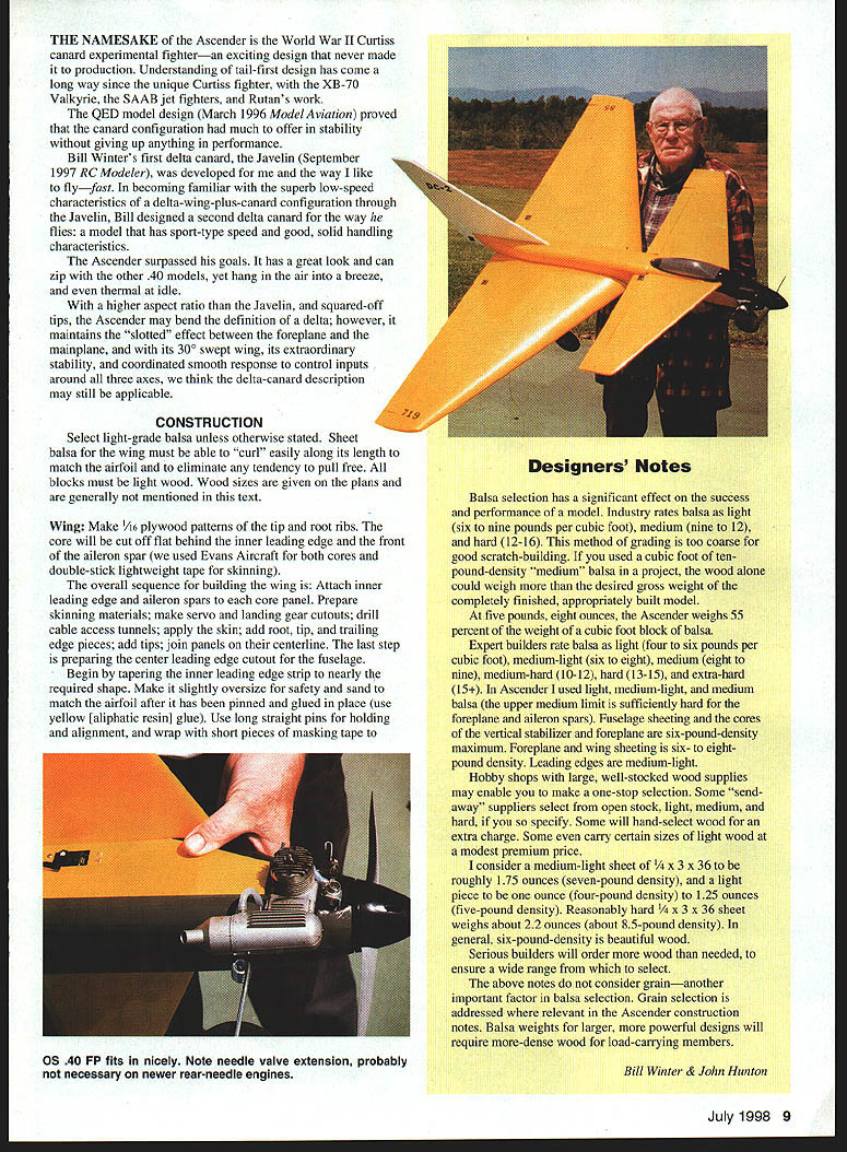
Designers' Notes
Balsa selection has a significant effect on the success and performance of a model. Industry rates balsa as light (6–9 lb/ft³), medium (9–12), and hard (12–16). This method of grading is too coarse for good scratch-building. If you used a cubic foot of 10-lb-density "medium" balsa in a project, the wood alone could weigh more than the desired gross weight of a completely finished, appropriately built model.
At 5 lb 8 oz, the Ascender weighs 55 percent of the weight of a cubic foot block of balsa.
Expert builders rate balsa as light (4–6 lb/ft³), medium-light (6–8), medium (8–9), medium-hard (10–12), hard (13–15), and extra-hard (15+). In the Ascender I used light, medium-light, and medium balsa (the upper medium limit is sufficiently hard for the foreplane and aileron spars). Fuselage sheeting and the cores of the vertical stabilizer and foreplane are six-pound-density maximum. Foreplane and wing sheeting is six- to eight-pound density. Leading edges are medium-light.
Hobby shops with large, well-stocked wood supplies may enable you to make a one-stop selection. Some "send-away" suppliers select from open stock light, medium, and hard if you so specify. Some will hand-select wood for an extra charge. Some even carry certain sizes of light wood at a modest premium price.
I consider a medium-light sheet of 1/4" x 3" x 36" to be roughly 1.75 oz (seven-pound density), and a light piece to be 1.0–1.25 oz (four- to five-pound density). Reasonably hard 1/4" x 3" x 36" sheet weighs about 2.2 oz (≈8.5-lb density). In general, six-pound-density is beautiful wood.
Serious builders will order more wood than needed to ensure a wide range from which to select.
The above notes do not consider grain—another important factor in balsa selection. Grain selection is addressed where relevant in the Ascender construction notes. Balsa weights for larger, more powerful designs will require more-dense wood for load-carrying members.
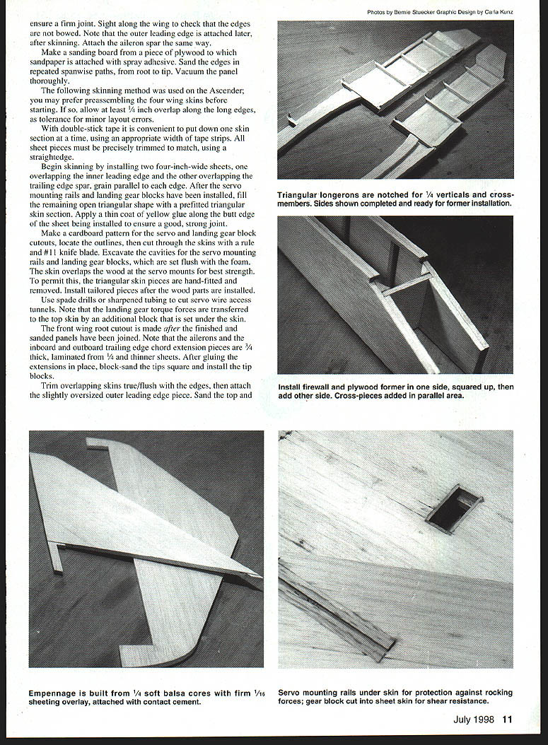
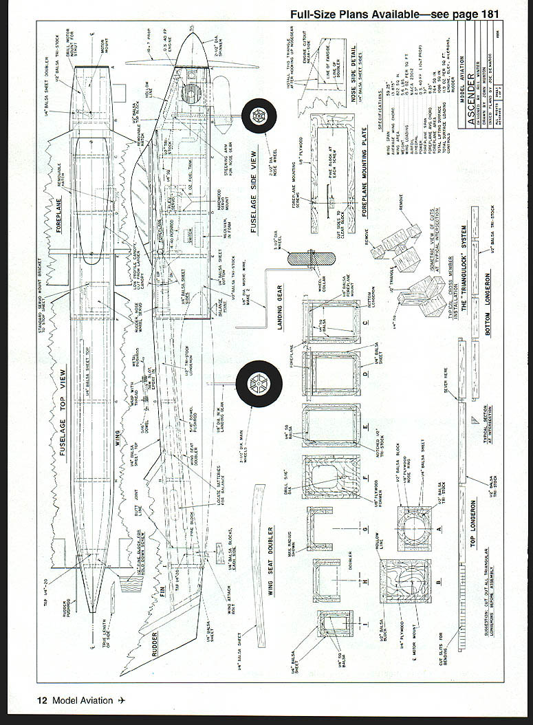
Fuselage
Construction of the Ascender fuselage is somewhat unusual, with our "triangulock" detailing—the use of slotted triangle stock to key in uprights and crossmembers for easy and accurate building.
Cut out all triangular longerons and notch them accurately as shown on the plans. Make a thin cardboard pattern of the mainplane (wing) cutout area and accurately scribe the sides with a pencil around the outlines to be removed as well as the doubler. Cut the fuselage sides to outline shape.
Attach the triangles to each side, being very careful to get them in accurate position. Be sure to make a right side and a left side. Install the wing, foreplane, and nose doublers.
Pin the blanks together back-to-back and true all edges to identical outlines. Place a sheet of sandpaper on the workbench and slide the paired sides back and forth with a milling action. Part the sides, then taper the aft ends for joining later.
Install all vertical members in each side. Cut the firewall (install blind nuts now) and both plywood formers. Install the firewall and formers into one side, using a triangle to true them, then attach the other side. Do not pull the rear together yet.
Install all crosspieces between the firewall and along the straight-sided portion of the fuselage, then pull in the tail after the assembly is dry (temporary crosspieces can be added at the foreplane area). True the top and bottom with a sanding block, then install the top and bottom sheeting. Add the nose ring and required doublers.
Basic shaping and sanding of the fuselage should be done now. Corners should be well-rounded, but leave them square at the wing-root leading edge and at the foreplane mount area.
Prepare the plywood foreplane seat. Be sure to install the hardwood blocks to the underside of the plywood plate to receive the hold-down screws. Check that the foreplane area is level and true, then mount the plywood plate.
The fiber-reinforced plastic engine mount used had holes for the typical nosewheel strut, but because the mount is turned on its side, similar holes (5/32") must be drilled sideways through the stock mount.
Cover the engine-mount bolt holes with masking-tape tabs, then coat the front face of the firewall with epoxy and allow to set. Trial-install the engine and nose gear. Install the fuel tank and as much plumbing as can be done at this stage.
Install the servos; note that the foreplane servo is mounted directly through the side of the fuselage, with one end mounted to a 1/4" square vertical and the other to a 1/4" square hardwood block. The rudder/nosewheel servo can be mounted in a stock bracket from the inside top sheeting.
The canopy is assembled after the foreplane is in position. Mark the centerline of the top rear fuselage sheet and cut holes for the fin attachment tabs.
Vertical Stabilizer and Foreplane
Build the vertical stabilizer and foreplane by assembling a light balsa core with hard balsa for the fin and foreplane main spars. Make lightening holes on the outer areas of the cores as indicated. Use a Forstner bit, or make a hole-cutting tool from large thin-walled tubing with its cutting edges sharpened. Use a repetitive twisting motion. Pretape the entry side for protection.
Sheet with the skins at a diagonal grain to the core. Sand the leading edge square, then add the leading-edge piece, which is full thickness. Install the plywood foreplane reinforcements. Sand all surfaces to shape with the sanding board, then smooth with fine sandpaper.
Cut and glue the block for the wing hold-down bolt, but do not drill the bolt hole until the wing has been finished and fitted. Assemble the two elevator blanks and the connecting dowel piece snugly against the rear of the main surface, with a strip of waxed paper between them and the foreplane. Pin all parts down accurately. Use epoxy on the dowel joint.
After the epoxy has cured, pick up the work, then taper/sand the elevator assembly with a sanding board. Do not feather the trailing edge of the elevators or rudder (see plan). Shape the elevator hinge line as shown.
Canopy / Foreplane Hatch
Cut the canopy base from 1/8" sheet (match to your canopy shape if required). Trial-fit the canopy to the base by gently sanding the wood to match the canopy slope around the perimeter. The mount will be glued later to the top of the built-up fairing block, which is cross-sectioned to fit on top of the foreplane.
Preassembly
Mark locations of the foreplane hold-down screws. Pin the foreplane assembly over the plywood foreplane mount. Drill guide holes for #10 self-tapping sheet-metal screws. There are three such screws to hold down the removable foreplane (for tank access) and two smaller screws in the canopy assembly. After installing the screws, remove them and strengthen the holes with CyA. Temporarily install the hinges and elevator horn, but remove them until covering is complete.
Fit the wing to the fuselage before installing the hold-down dowel. The rib profile on the fuselage will be fairly accurate, but the inside doublers will have to be tapered and shaped to fit the wing. Run masking tape along the top of the wing where it will meet the fuselage and coat the tape with lipstick. Seat the wing, remove it, and trim away the material that is marked with lipstick. Repeat the process until the wing is seated and is level with the foreplane.
With the wing accurately mated to the fuselage, drill a 3/16" hold-down hole through the wing and the rear plywood block in the fuselage. Remove the wing and drill the wing alone with a 1/4" clearance bit. Tap the hole in the plywood mounting piece for the 1/4-20 nylon hold-down screw. Realign the wing on the fuselage and attach with the mounting bolt.
Put a dab of modeling clay on the wing-mount faceplate and push the wing into place. Remove the wing and drill for the dowel where indicated. Epoxy the dowel pegs into the faceplate. To ensure accuracy, put epoxy into the hole in the plate, rub a bit on the dowel, and reposition the wing, making sure of accurate alignment. Drill landing-gear wire holes in the hardwood blocks.
The main landing gear is shaped from 1/8" music wire, cut long to allow for bending. Make bends using a vise, hammer, etc. (Hint: file a small notch in the vise jaws to provide a small radius to prevent breaking the wire at the bends). Trial-mount the landing gear and temporarily install the mounting screwplates. Check alignment and symmetry of the landing gear wire. Remove before covering the wing.
Covering / Painting
On the prototype we used 21st Century film by Coverite. Prepare all surfaces by sanding with a block to true them. Touch up curves with folded sandpaper. Wipe off or vacuum balsa dust. Follow the film covering instructions accurately, but generally try to pull the film tight enough during adhesion to minimize the amount to be shrunk.
Final Assembly
Install the landing gear, RC gear, linkage, engine, and engine mount. Hook up the fuel tank plumbing. Install the antenna full length.
It is critical to make the model balance where indicated. Use ballast if necessary. Also check side-to-side balance and correct with tip weight if needed. Check for free control movements of the indicated amounts.
Flying
There are two areas in which this delta-canard model presents differences from the flight characteristics of most normally configured models:
- How it looks in the air. Keep the model close and at least "one mistake high" until you are familiar with how it looks. It helps greatly to color the top light and the bottom dark. A white fin also helps.
- Landing. With its excellent stall characteristics, it is very easy to get the Ascender too slow on landing and therefore not have enough airspeed left to flare. Keep speed up until it's time to flare and it will not bounce at touchdown.
In normal flight the Ascender responds gracefully to the controls and provides good feedback. Rudder is not needed for coordinated turns, yet it will turn with rudder alone. It can seem to hover into a breeze like a kestrel waiting to pounce on prey. All controls remain effective at very low velocities, but the rudder is very useful there. Stalls must be forced and are not to be feared.
The prototype was flown with foreplane-elevator control only and with mixed elevon. If your RC system is capable of mixing controls, you might try it for more responsiveness. We mixed flap to elevon for additional up-control only (no down). This gave us additional up for slower landings.
You may want to experiment with moving the center of gravity (CG) back incrementally (1/4" at a time) by shifting the battery or by adding ballast to gain more sensitive control response, but do not expect the Ascender to snap or spin. It will invert, roll well (a little down helps when inverted), and it loops just fine. The Ascender flies similar to any other sport model—and does it with class.
John Hunton 9154 Rixeyville Rd. Rixeyville, VA 22737
Bill Winter 12811 Melville Ln. Fairfax, VA 22033
Transcribed from original scans by AI. Minor OCR errors may remain.

