

Assembling an Electric-Powered ARF from the Ground Up
by Bob Aberle
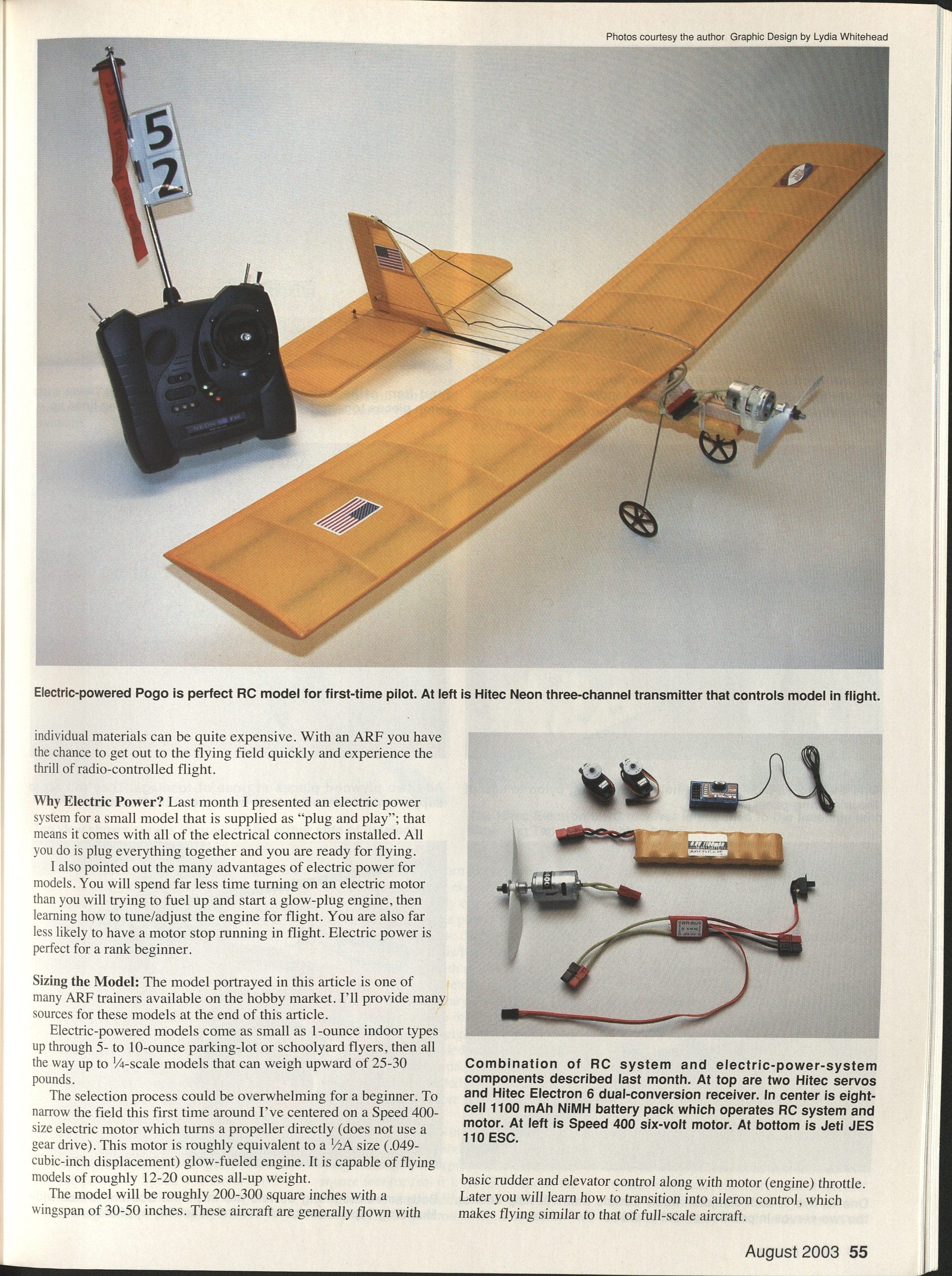
If you have followed this series from the beginning, you know that I have already discussed a typical three-channel radio-control system (the Hitec Neon), and last month I introduced the components of an electric power system capable of flying a radio-control (RC) model aircraft. At this point we have the RC and power systems, and we need a model to complete the package.
There are many aircraft choices today for the beginning RC modeler. You can purchase a model that is essentially ready to fly, with the motor and radio system installed at the factory. With a few minutes of your time you can be at the flying field for that first flight lesson.
There are not that many ready-built models available yet; some are not the best choice for a beginner, and they can be quite expensive. A better choice is a model that comes essentially prebuilt but requires final assembly and installation of the radio and power systems. I favor this approach for a starter, and that will be the subject of this article.
Two other categories of model aircraft with which you will eventually become familiar are kit building and scratch building. With a manufactured kit you assemble precut pieces, cover the airplane as applicable, and install all equipment. Scratch building involves purchasing plans or designing your own, buying wood and materials, cutting out all parts, assembling, covering, and installing equipment.
A beginner can acquire the skills necessary for kit or scratch building with proper, detailed instructions. I have an extremely simple design I call the "Scratch-One," which will be featured two installments from now. That article will enable you to use the same RC and power system in your first scratch-built model.
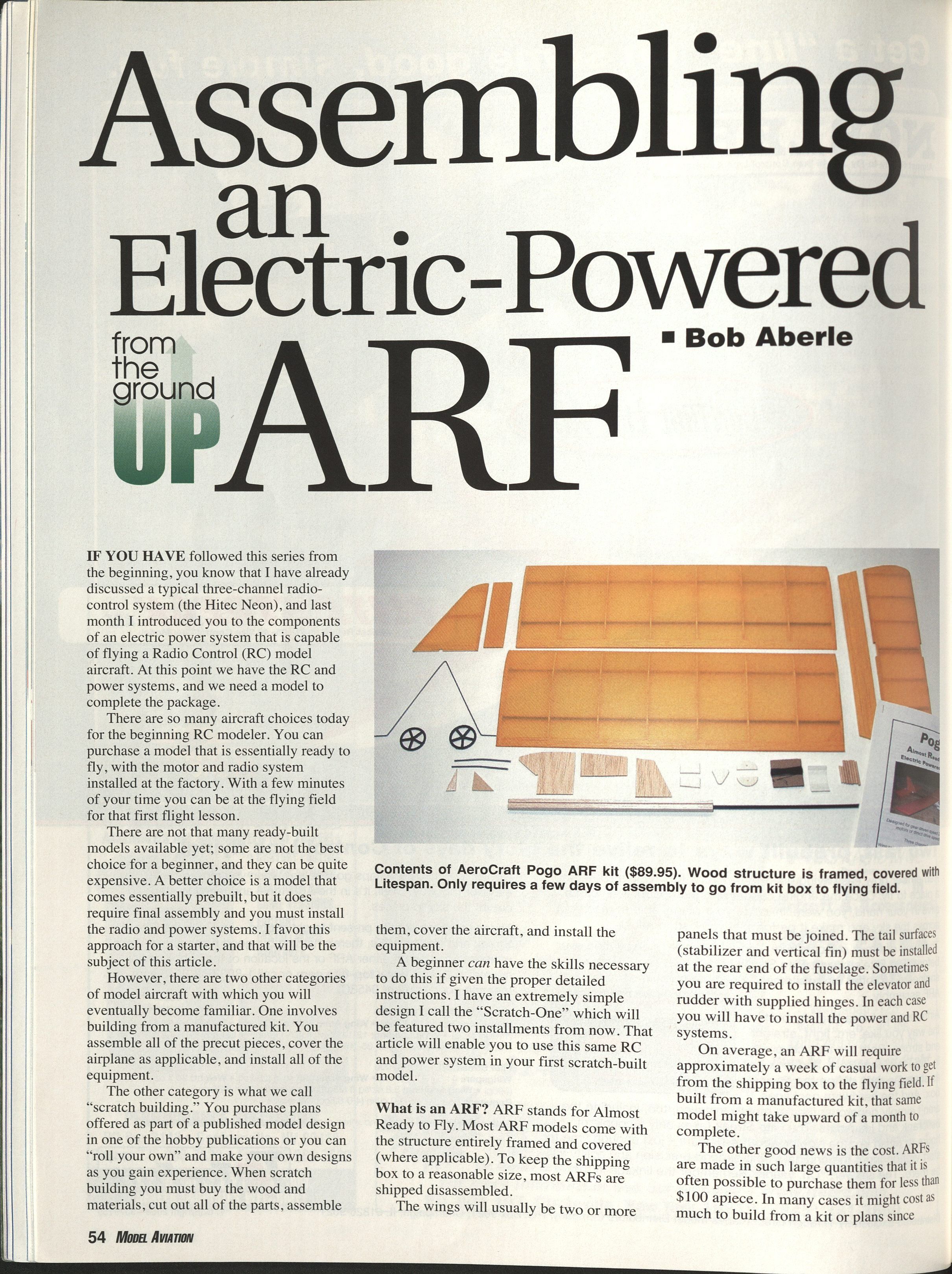
What is an ARF? ARF stands for Almost Ready to Fly. Most ARF models come with the structure entirely framed and covered (where applicable). To keep the shipping box to a reasonable size, most ARFs are shipped disassembled. Wings are usually two or more panels that must be joined. Tail surfaces (stabilizer and vertical fin) must be installed at the rear of the fuselage. Sometimes you must install elevator and rudder hinges. In each case you will have to install the power and RC systems.
On average, an ARF will require approximately a week of casual work to get from the shipping box to the flying field. If built from a manufactured kit, that same model might take upward of a month to complete.
The other good news is the cost. ARFs are made in large quantities and can often be purchased for less than $100. In many cases it might cost as much to build from a kit or plans, since individual materials can be quite expensive. With an ARF you have the chance to get to the flying field quickly and experience the thrill of radio-controlled flight.
Why electric power? Last month I presented an electric power system for a small model that is supplied as "plug and play"; that means it comes with all electrical connectors installed. All you do is plug everything together and you are ready for flying. Advantages of electric power include much less prep time than starting and tuning a glow-plug engine, and far less likelihood of a motor stopping in flight. Electric power is perfect for a rank beginner.
Sizing the Model
The model portrayed in this article is one of many ARF trainers available on the hobby market. Electric-powered models range from tiny indoor types up through parking-lot flyers and to 1/4-scale models weighing 25–30 pounds or more. To narrow the field for beginners, this series centers on a Speed 400-size electric motor that turns a propeller directly (no gear drive). This motor is roughly equivalent to a 1/2A (.049 cu. in.) glow engine and is capable of flying models of roughly 12–20 ounces all-up weight.
Typical characteristics for this class:
- Wing area: roughly 200–300 square inches
- Wingspan: roughly 30–50 inches
- Control: rudder and elevator plus throttle (basic three-channel); ailerons can be added later
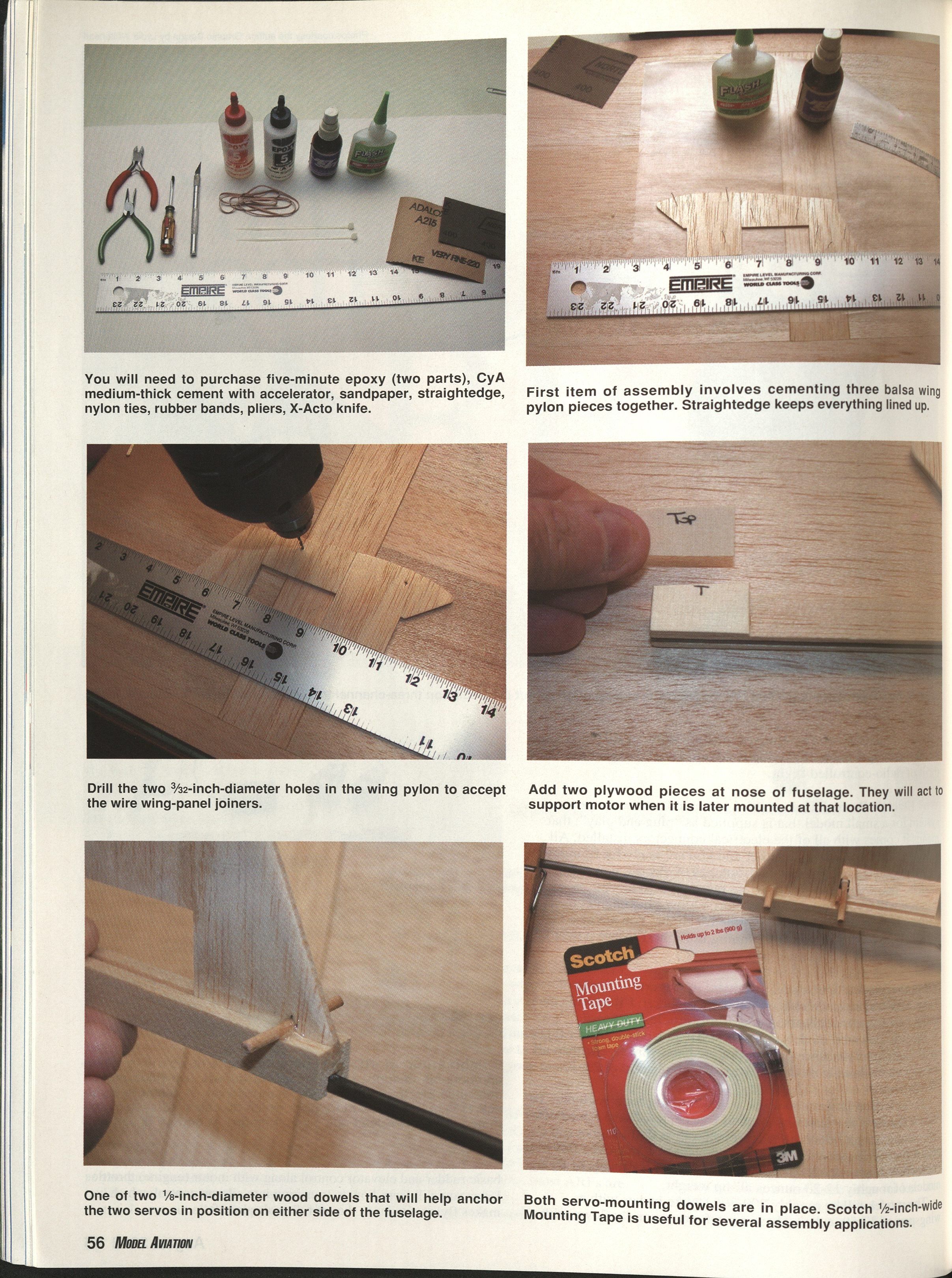
You will need some adhesives and basic tools for assembly:
- Five-minute epoxy (two parts)
- Medium-thick CyA (cyanoacrylate) glue with accelerator
- Sandpaper, straightedge, nylon ties, rubber bands, pliers, X-Acto knife
Assembly begins with cementing three balsa wing-pylon pieces together and drilling two 3/32-inch-diameter holes in the wing pylon to accept the wire wing-panel joiners. Add two plywood pieces at the nose of the fuselage to support the motor when mounted. Two 1/8-inch-diameter wood dowels help anchor the two servos on either side of the fuselage. Scotch 1/2-inch-wide Mounting Tape is useful for several assembly applications.
There are computer programs and resources that can help size motor, gear ratio, propeller, and battery (cell count and capacity). For this series, choices have been simplified to make learning easier.
AeroCraft Pogo
My choice for this series is Craig Wagner's AeroCraft Pogo. It is available direct from AeroCraft for $89.95 plus $6 shipping. Kirk Massey of New Creations R/C offers the same kit and supplies the complete electric power system described last month.
The Pogo is intended for geared Speed 280/300 power or Speed 400 direct drive. Geared motors can keep model weight down to roughly 12–13 ounces, but performance can be marginal in winds over 5 mph. A Speed 400 provides a comfortable power reserve for beginner pilots and their instructors.
Key Pogo figures:
- Wing area: 216 sq. in.
- Weight with recommended 8-cell 1100 mAh NiMH battery: 15.8 ounces
- Wing loading: 10.5 oz./sq. ft. (suitable for beginners)
With a Speed 400 the motor-prop-battery combination can give roughly 5–6 minutes at full throttle; throttling back in flight can extend run time to 8–10 minutes, comparable to a small fuel engine on a typical tank.
What Comes in the Kit?
As received, the Pogo comes with:
- Two assembled and covered wing panels
- Assembled and covered stabilizer and elevator
- Vertical fin and rudder
- Fuselage consisting primarily of a carbon tube (approximately 1/4 inch in diameter)
- All necessary hardware for final assembly (control horns, clevises, control rods, hinges, wheels, etc.)
What Will You Still Need to Buy?
- Medium gap-filling CyA (cyanoacrylate) glue and accelerator (I used NHP medium from Balsa Products Inc.)
- Five-minute epoxy (I used NHP brand)
- Double-stick 1/2-inch-wide mounting tape (Scotch 110) for servos, receiver, speed controller, and motor mounting
- Nylon ties for motor attachment and wire bundling (RadioShack)
- Small rubber bands for securing servos, receiver, and battery pack (Staples, Office Max, etc.)
- Clear silicone adhesive (small amount)
Tools Required
- X-Acto knife with #11 blade
- Needle-nose pliers and diagonal-cutting pliers
- Small Phillips-head screwdriver (for servo output arm changes)
- Electric drill with bits: 1/16, 3/32, 1/8, and 3/16 inch
- Straightedge
- Sandpaper (200 and 400 grit recommended)
With most ARFs, accessory parts such as control horns, clevises, control rods, hinges, and wheels are included, but their type and quality may vary. For the Pogo, everything necessary was supplied and used, with a few personal exceptions noted below.
Instructions and Assembly Notes
The AeroCraft instruction manual was well organized and easy to follow; diagrams are adequate though there are no photos. I followed the recommended assembly procedure exactly and will only note variations and useful tricks I found.
General assembly highlights:
- Epoxy the assembled balsa wing pylon into the precut groove in the forward fuselage.
- Two dowels mount the two RC servos to the fuselage; a rubber band around each servo holds it against the dowels.
- To make the servo mounts firmer: remove each servo, seal the balsa surface with CyA, apply double-stick mounting tape to the servo area, press the servo against the tape, then reapply the rubber band.
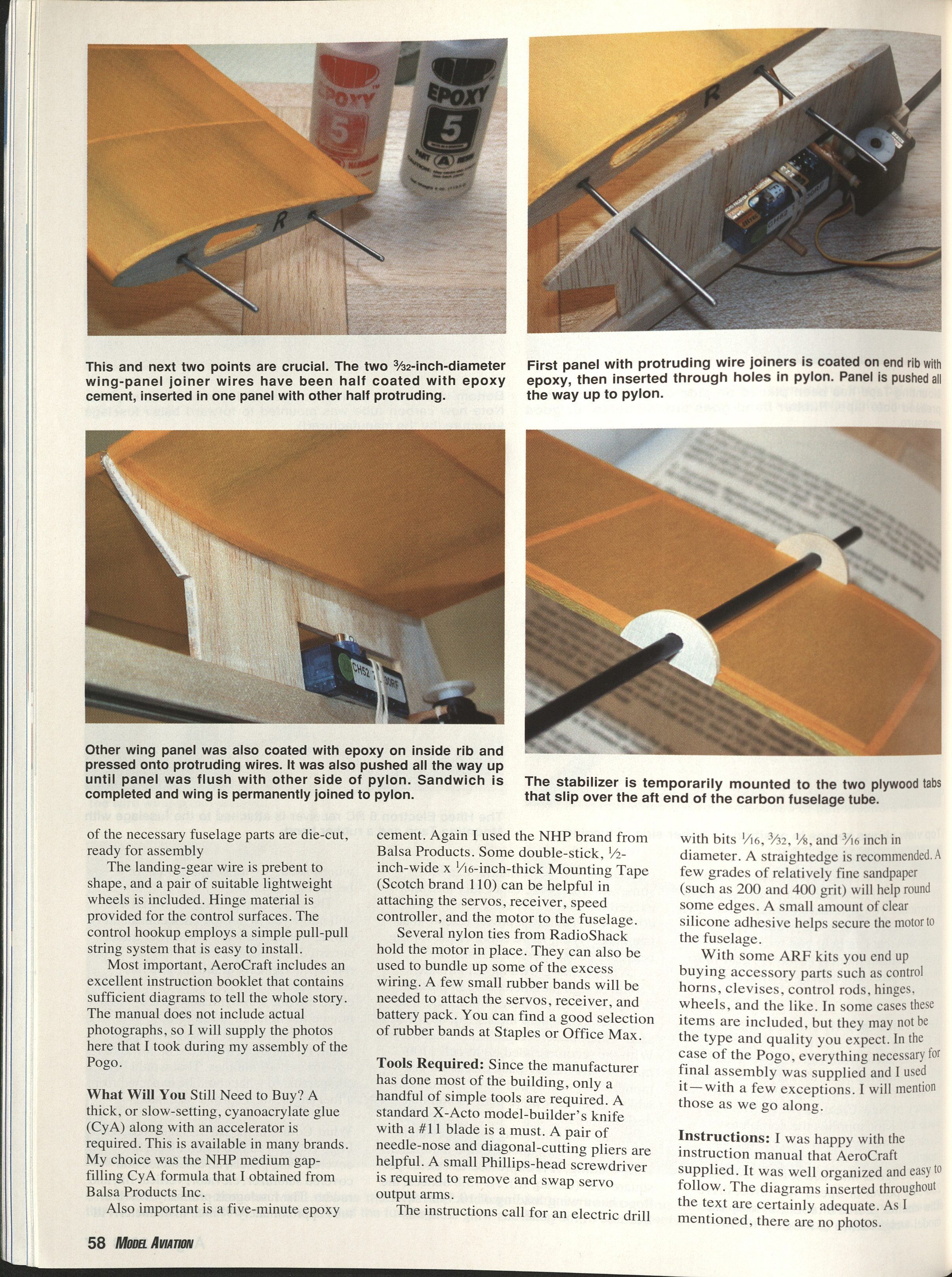
- The wing panels are joined on either side of the wing pylon like a sandwich. The wings are permanently cemented to the pylon once installed.
- I used five-minute epoxy on the 3/32-inch wing-joiner wires for strength. Procedure:
- Coat half of each joiner wire with epoxy and insert the wires halfway into the two holes in the carbon wing spars (one panel at a time).
- Let these cure (~15 minutes).
- Pass the wires through the holes at the top of the balsa wing pylon and trial-fit both panels.
- Remove panels, quickly apply epoxy inside the wing panels and on the protruding wires, then assemble and hold until set.
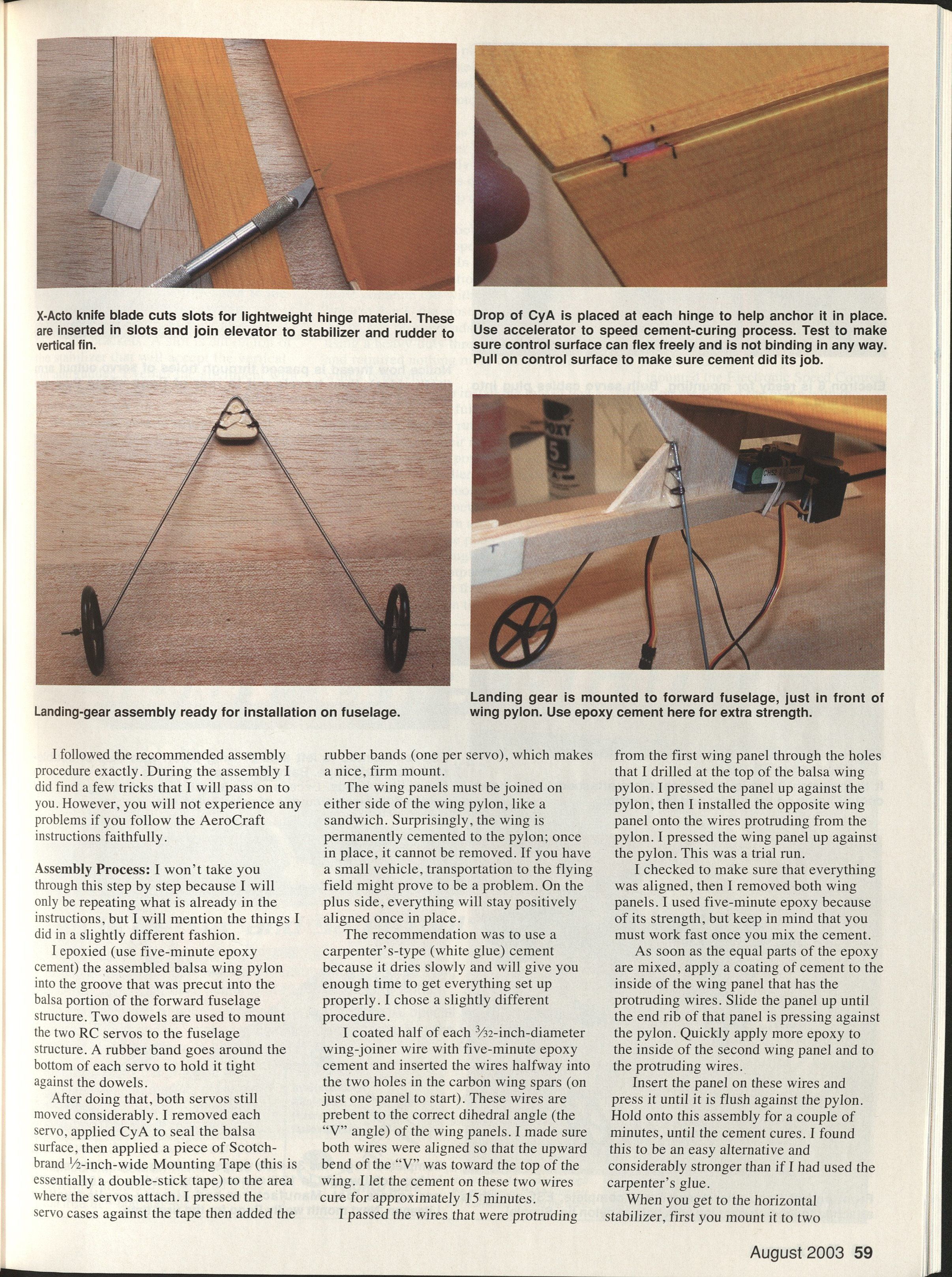
- For the horizontal stabilizer: mount the plywood support pieces, slide the stabilizer off the carbon boom, install hinge material in knife slots cut into the surfaces for elevator and rudder, and leave enough separation for proper flex. A drop of CyA at each hinge helps anchor them—pull on surfaces after curing to verify.
- Eyeball alignment of the stabilizer relative to the wing before applying epoxy to stabilizer mounting brackets. A slot on top of the stabilizer accepts the vertical fin and rudder; align and secure with CyA.
- Landing gear: attach the wire to a plywood bracket using the supplied strong thread. Wheels are held in place with thread and CyA.
- Receiver: apply double-stick mounting tape under the receiver and use a rubber band to hold it in position.
- Motor: place mounting tape on the top of the fuselage where the motor mounts, secure the motor with two nylon ties, and add clear silicone adhesive to prevent tie movement and motor case rotation.
- Battery pack: held in place with four small rubber bands for easy removal for charging or swapping.
- Control linkages: AeroCraft recommends a pull–pull system using heavy-duty thread (supplied). Steps:
- Power up the RC system and ensure rudder and elevator trims are neutral. Remove the propeller first to prevent accidental motor start.
- With trims neutral, power off the system.
- Pass thread through the two outer holes of the servo output arm; a drop of CyA prevents slippage.
- Run both ends of the thread to the rear of the model and attach one to the top and the other to the bottom of the dowel control horn; wrap and secure with CyA.
- Repeat for the rudder. You end up with four thread runs from the servos to the rear (two elevator, two rudder).
- Verify correct control directions and amount of movement before flight.
Mount the Electronic Speed Control (ESC) on the side of the pylon with double-stick mounting tape. Bundle excess cabling with nylon ties. Tie the ESC switch to a landing-gear leg. Run the receiver antenna up to the top of the vertical fin and attach with a nylon tie. Do not cut excess antenna wire—this will reduce radio range.
#### Assembly notes/captions found in the kit documentation
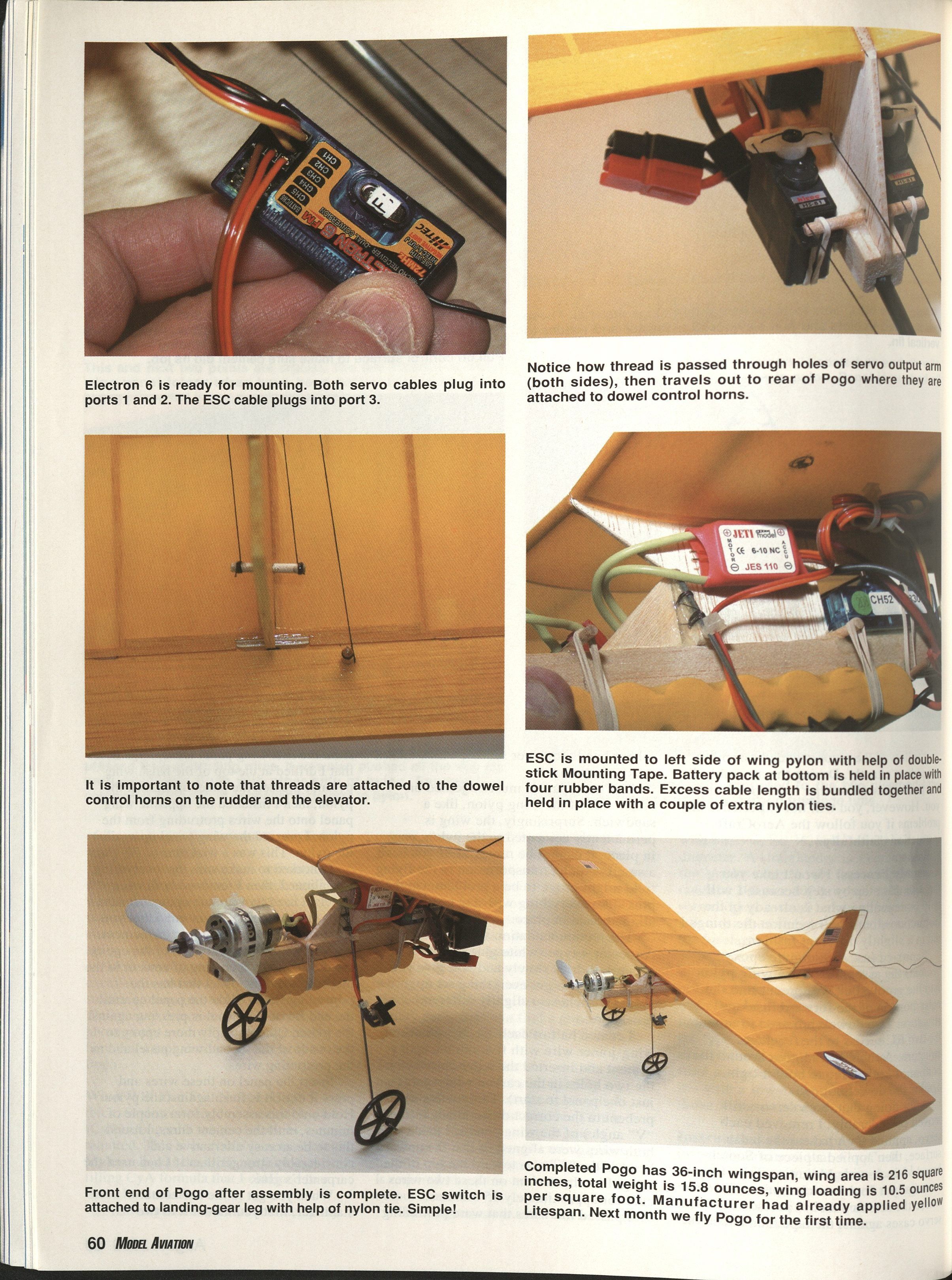
- Electron 6 is ready for mounting. Both servo cables plug into ports 1 and 2. The ESC cable plugs into port 3.
- Thread is passed through holes of the servo output arm (both sides), then travels out to the rear of the Pogo where they are attached to dowel control horns.
- Threads are attached to the dowel control horns on the rudder and the elevator.
- ESC is mounted to the left side of the wing pylon with double-stick mounting tape. The battery pack at the bottom is held in place with four rubber bands. Excess cable length is bundled and held with nylon ties.
- The ESC switch is attached to a landing-gear leg with a nylon tie.
- Completed Pogo: 36-inch wingspan, wing area 216 sq. in., total weight 15.8 ounces, wing loading 10.5 oz./sq. ft. Manufacturer had applied yellow Litespan.
How Long Did It Take?
I timed myself during assembly (slowed by photos). It took roughly three days at about six hours per day—approximately 18 working hours total.
Final Balance and Weight
The Pogo's final weight was 15.8 ounces—slightly above the specified maximum of 13 ounces. The 1100 mAh battery alone weighs about 6 ounces. The model's center of gravity (CG) is specified as two inches back from the wing leading edge. With the battery pack located just behind the motor, the Pogo balanced almost perfectly and required no additional ballast.
Next Month
Next month I will finish the Pogo's checkout and take you to the field for the first series of flights. Every installment of this series is posted on AMA's website in the Model Aviation section at http://modelaircraft.org/mag/index.htm for reference. Your comments and questions are welcome.
MA Bob Aberle
Manufacturers / Suppliers
- New Creations R/C — Complete electric power system described last month
Box 497 Willis, TX 77378 (936) 856-4630
- AeroCraft Ltd. — Excellent small electric-powered ARFs
432 Hallett Ave. Riverhead, NY 11901 (631) 369-9319 www.aerocraftrc.com
- Dymond Modelsports
3904 Convoy St. San Diego, CA 92111 (858) 495-0092 Fax: (858) 495-0096 and 683 N. Main St. Oshkosh, WI 54901 (920) 303-1100 Fax: (920) 303-2021 www.rc-dymond.com
- Great Planes Model Distributors
Box 9021 Champaign, IL 61826 (800) 637-7660 or (217) 398-6300 [email protected]
- Hobby Lobby International
5614 Franklin Pike Cir. Brentwood, TN 37027 (615) 373-1444 Sales: [email protected] www.hobby-lobby.com
- Horizon Hobby Inc.
4105 Fieldstone Rd. Champaign, IL 61822 (217) 355-9511 www.horizonhobby.com
- Northeast Sailplane Products
948 Hercules Dr., Suite 12 Colchester, VT 05446 (802) 655-7700 www.nesail.com
- Tower Hobbies
Box 9078 Champaign, IL 61826 (800) 637-6050 www.towerhobbies.com
Transcribed from original scans by AI. Minor OCR errors may remain.

