
AUTHENTIC SPOKED WHEELS
by Jon Putnam
Build lightweight custom wire wheels for your park flyer or free-flight model.
It may seem intimidating, but building wire wheels for your model can have your flying buddies turning their heads and saying, "Where did you buy those little gems?" They'll look at you as if you just took on the status of a watchmaker when you say, "I made them myself."
My wire-wheel saga grew from an interest in rubber-powered pre-World War I Pioneer aircraft. A quick glance at the requirements of the "Magnificent Men"-era machines made me realize that I needed to learn how to make light wire wheels and radial engines, or the game was over before I started. There's no use in building a lightweight Blériot and not having the wheels or engine to make it look right.
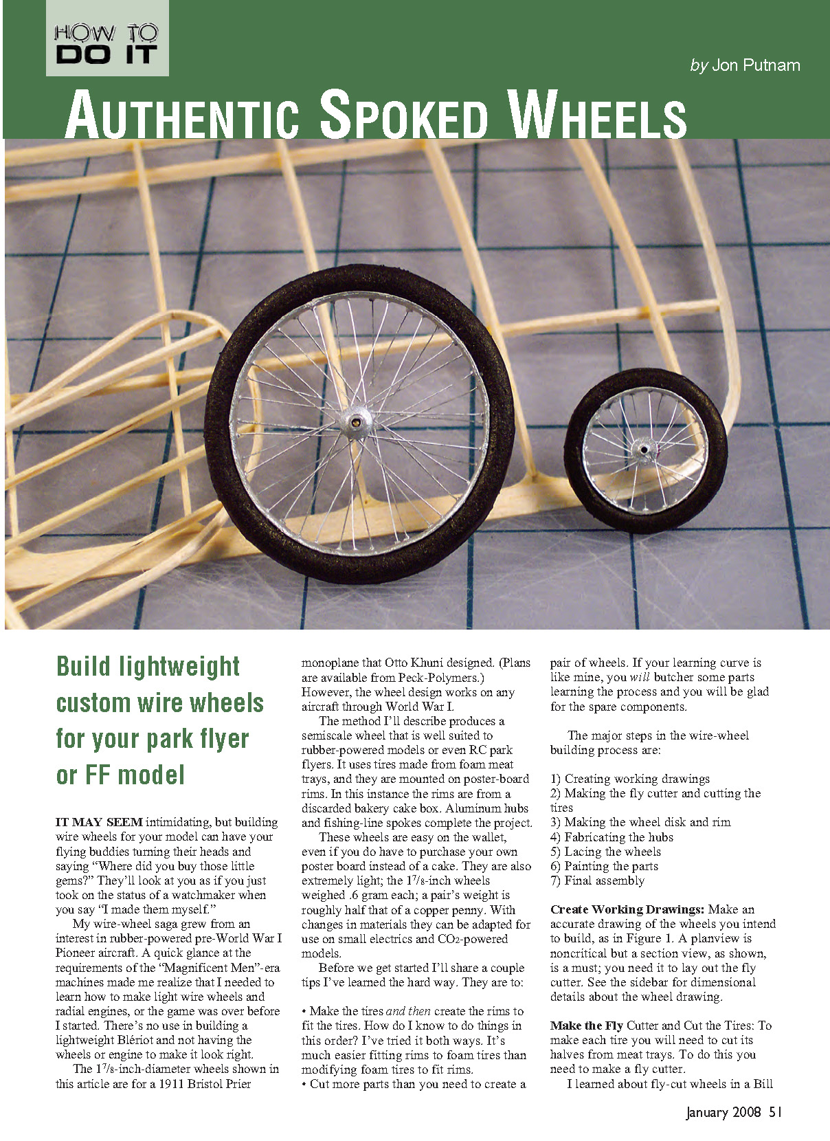
The 1 7/8-inch-diameter wheels shown in this article are for a 1911 Bristol Prier monoplane that Otto Khuni designed (plans are available from Peck-Polymers). However, the wheel design works on any aircraft through World War I.
The method described here produces a semiscale wheel that is well suited to rubber-powered models or even RC park flyers. It uses tires made from foam meat trays, mounted on poster-board rims (in this case from a discarded bakery cake box). Aluminum hubs and fishing-line spokes complete the project.
These wheels are easy on the wallet, even if you do have to purchase your own poster board instead of a cake box. They are extremely light; the 1 7/8-inch wheels weighed 0.6 gram each — a pair is roughly half the weight of a copper penny. With changes in materials they can be adapted for use on small electrics and CO2-powered models.
Before we get started, a couple of tips learned the hard way:
- Make the tires first and then create the rims to fit the tires. It's much easier fitting rims to foam tires than modifying foam tires to fit rims.
- Cut more parts than you need to create a pair of wheels. You will likely butcher some parts while learning the process and will be glad for spare components.
The major steps in the wire-wheel building process are:
- Creating working drawings
- Making the fly cutter and cutting the tires
- Making the wheel disk and rim
- Fabricating the hubs
- Lacing the wheels
- Painting the parts
- Final assembly
Create Working Drawings
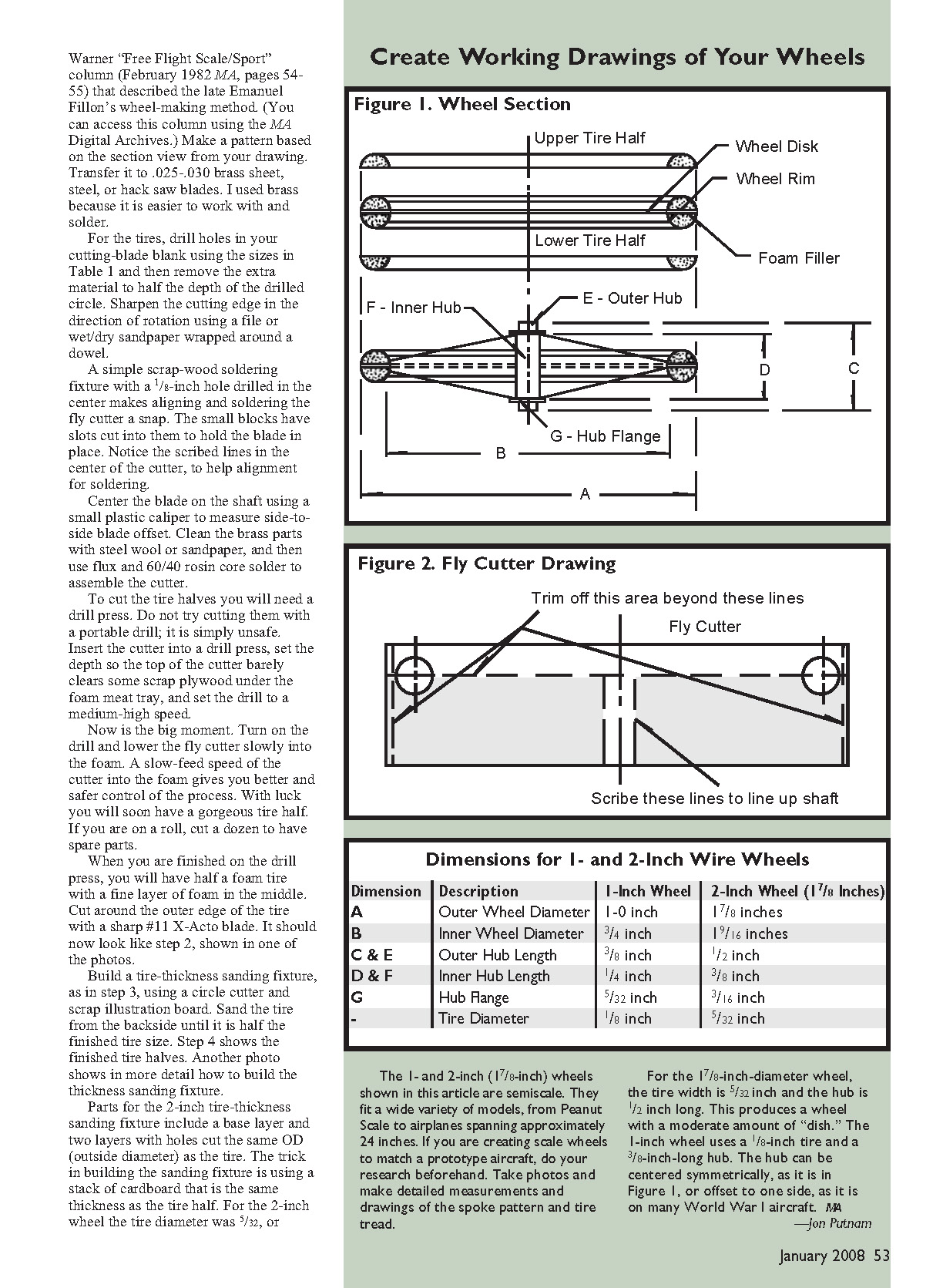
Make an accurate drawing of the wheels you intend to build. A plan view is noncritical, but a section view is essential; you need it to lay out the fly cutter and to determine tire thickness, rim shape, and hub dimensions.
Make the Fly Cutter and Cut the Tires
To make each tire you will need to cut its halves from foam meat trays. For this you will build a simple fly cutter and use a drill press.
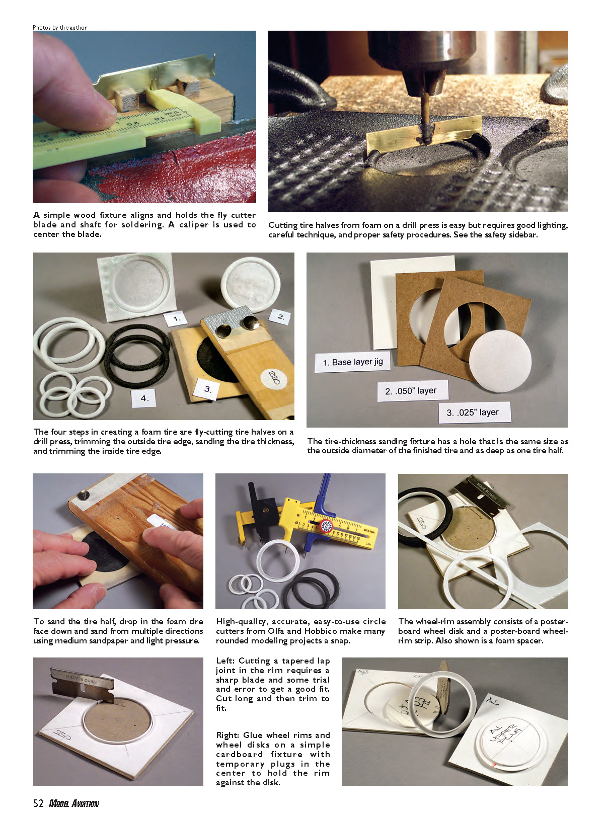
- A simple wood fixture aligns and holds the fly-cutter blade and shaft for soldering. A caliper is used to center the blade.
- Cutting tire halves from foam on a drill press is straightforward but requires good lighting, careful technique, and proper safety procedures (wear dust protection and follow drill-press safety).
- The four steps in creating a foam tire are:
- Fly-cutting tire halves on a drill press
- Trimming the outside tire edge
- Sanding the tire thickness
- Trimming the inside tire edge
- The tire-thickness sanding fixture has a hole the same size as the outside diameter of the finished tire and as deep as one tire half. To sand the tire half, drop the foam tire face down and sand from multiple directions using medium sandpaper and light pressure. When you begin to touch the cardboard stop, you are finished with that half.
Breathe easy — you are finished making (and breathing) foam dust. The tires are now ready for painting.
Circle Cutters
The key to success in making these wire wheels is using a good circle cutter. High-quality, accurate tools are available from Olfa and Hobbico. Tips for using circle cutters:
- Buy extra blades and use them. This is especially important for critical cuts or dense material.
- Use light pressure and make several thin passes rather than one heavy cut.
- Make test cuts on thin card stock or paper to save blades and material. Once the setting is correct, move to the final material.
- Rotate the material — not the cutter — for small parts such as the inside cuts of 1-inch wheels.
Make the Wheel Disk and Rim
The rim assembly consists of a poster-board wheel disk and a poster-board wheel-rim strip. A foam spacer from a take-home box fills the gap between tire halves.
- Cut wheel disks from poster board using the circle cutter. Make the outside cuts first. The disk’s finished size should be slightly smaller than the wheel’s finished size.
- Cut several thin foam spacers from the bottom of a foam take-home box to fill the tire gap. If the wheel disk is 0.025 inch thick, sand the foam to the same thickness before cutting holes.
- To cut the inside diameter of the wheel disk, make a mat-board fixture (two glued layers of mat board). Keep the plug you cut from the circle in the upper mat board and mark it (for example, “Plug”); you will use it to force the rim against the fixture.
- Lay out rim parts on poster board and make the rim strips longer than needed; trim to fit later. Lightly scribe the side that will be glued to the wheel disk before cutting strips.
- Mark two thin pencil lines in the middle of the strip and scribe a line on each side; these help the rim bend to its final curved cross-section and show centering when glued.
- Fit the rim strip in the fixture with marks facing out and cut a tapered lap joint. Glue the lap joint with a small amount of white glue before assembly.
- Use the plug to hold the rim firmly against the fixture. Slip the wheel disk over the rim, seat it against the plugs, trim the rim flush with the disk, glue the rim to the disk, and let it dry in the fixture before removal.
- Use heavier poster board (.020–.025 inch) or lighter (.015 inch) depending on available material. Many bakery boxes are a good source.
Note on materials:
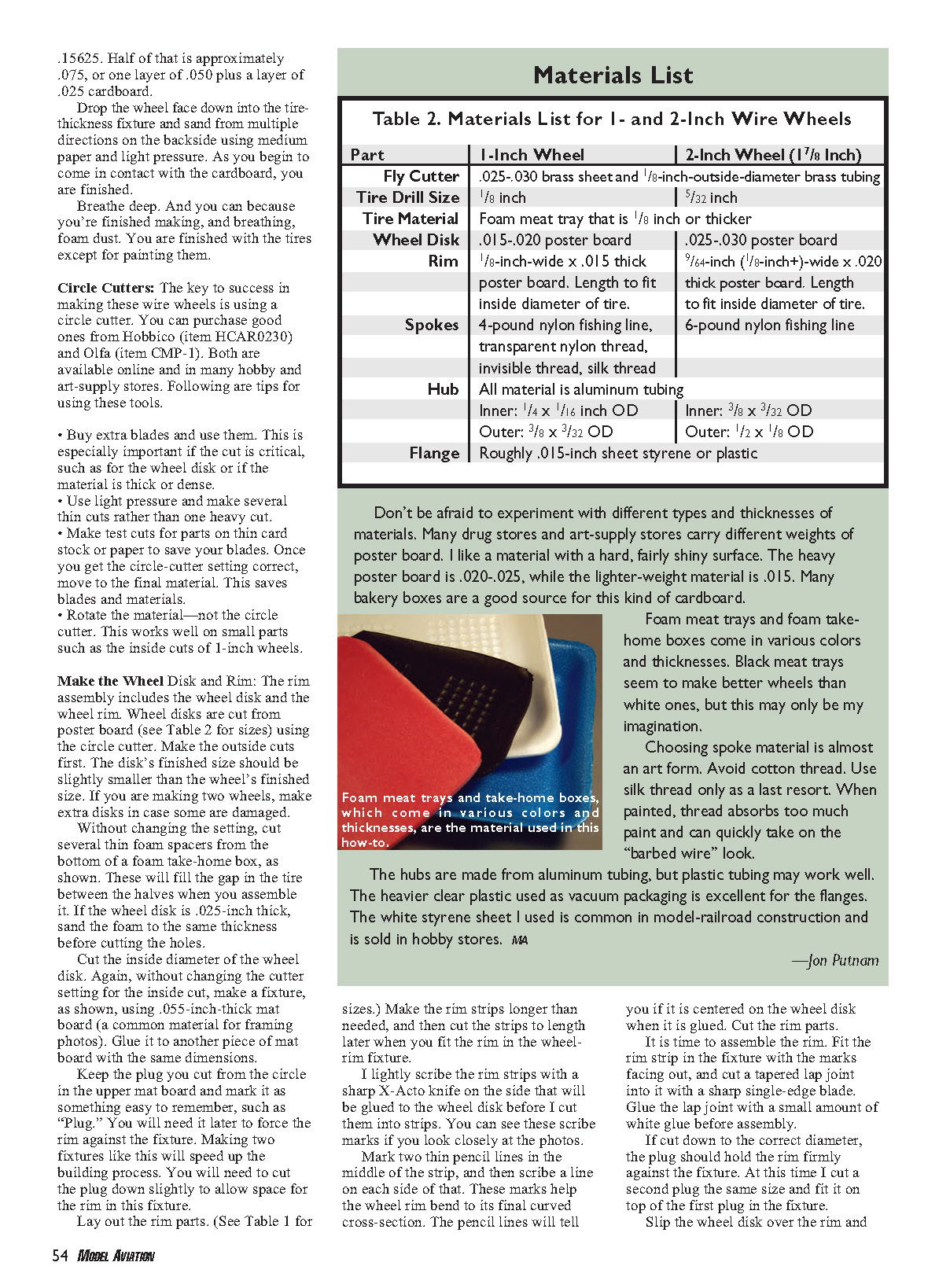
- Foam meat trays and foam take-out boxes come in various colors and thicknesses. Black trays often produce better-looking tires.
- Avoid cotton thread for spokes; silk only as a last resort. Threads absorb paint and can look rough when painted. Choose appropriate spoke material (see Lacing section).
- Hubs are typically made from aluminum tubing; plastic tubing or heavier clear vacuum-packaging plastic can work for flanges. White styrene sheet is useful for some hub parts.
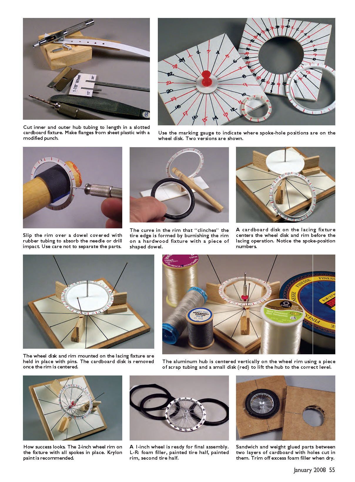
Fabricate the Hub
Hubs are built from telescoping aluminum tubing with plastic flanges.
- Make a mat-board cutting fixture for the tubing, and cut and trim with a single-edge razor blade, finishing with a file and sandpaper. Remove burrs on the inside with a #11 blade.
- Center the outer hub on the inner hub and glue them lightly with cyanoacrylate.
- Hub flanges can be made from plastic sheet. Begin by drilling holes the size of your inner hub in the plastic sheet (do a strip at once). Place a scrap cardboard backing under the sheet to absorb the punch impact.
- Modify a punch by fitting small pieces of telescoping tubing inside it to act as adapters. Glue a piece of tubing into a small block of wood, slide the punch over the tubing adapter, and strike firmly to produce small plastic washers or flanges.
(See tubing sizes in the parts list or reference materials for your chosen hub sizes.)
Dimensions for 1- and 2-Inch Wire Wheels
Note: the "2-inch" wheel discussed is actually 1 7/8 inches in outer diameter.
- A — Outer Wheel Diameter
- 1-Inch Wheel: 1.0 inch
- 2-Inch Wheel (1 7/8"): 1 7/8 inches
- B — Inner Wheel Diameter
- 1-Inch Wheel: 3/4 inch
- 2-Inch Wheel: 1 9/16 inches
- C & E — Outer Hub Length
- 1-Inch Wheel: 3/8 inch
- 2-Inch Wheel: 1/2 inch
- D & F — Inner Hub Length
- 1-Inch Wheel: 1/4 inch
- 2-Inch Wheel: 3/8 inch
- G — Hub Flange
- 1-Inch Wheel: 5/32 inch
- 2-Inch Wheel: 3/16 inch
- Tire Diameter (thickness)
- 1-Inch Wheel: 1/8 inch
- 2-Inch Wheel: 5/32 inch (0.15625 in)
- Half of 5/32 is approximately 0.078125 in (roughly one layer of 0.050 in plus a layer of 0.025 in cardboard)
The 1 7/8-inch wheel uses a 5/32-inch tire and a 1/2-inch-long hub for a moderate amount of dish. The 1-inch wheel uses a 1/8-inch tire and a 3/8-inch-long hub. Hubs can be centered symmetrically or offset to one side for the dished appearance used on many World War I aircraft.
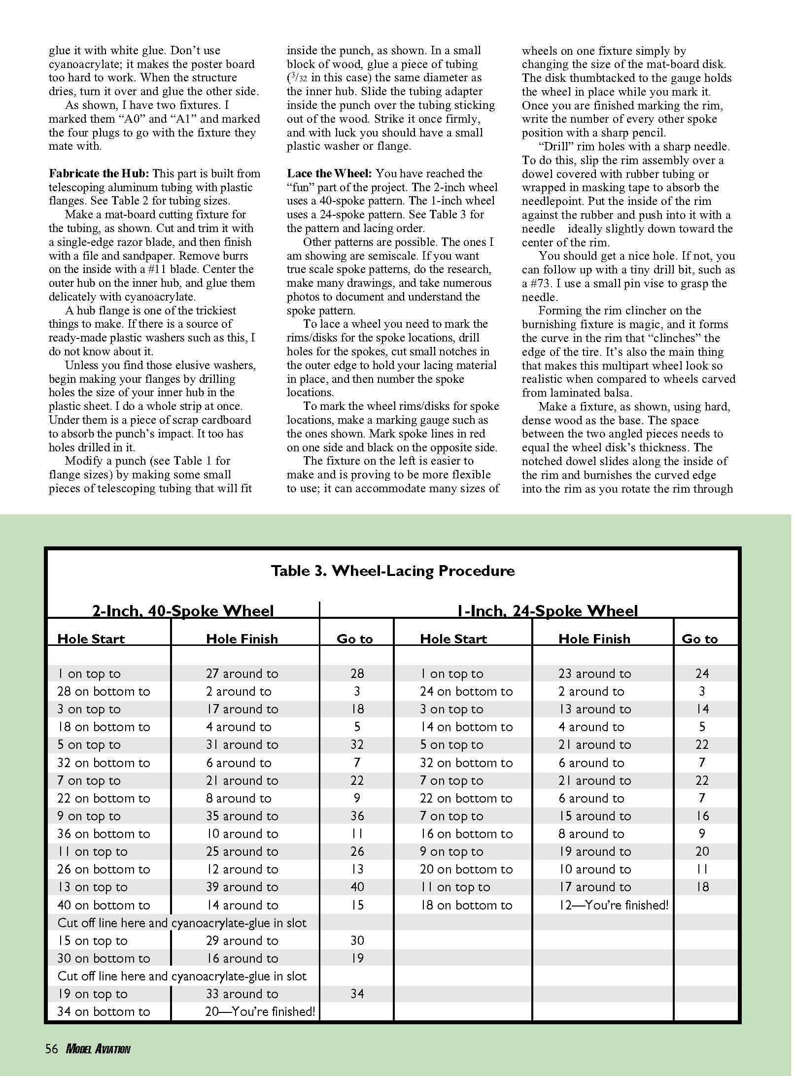
Lace the Wheel
Lacing is the most enjoyable part.
- The 2-inch (1 7/8") wheel shown uses a 40-spoke pattern. The 1-inch wheel uses a 24-spoke pattern. Other patterns are possible; for true scale patterns, do research and take many photos.
- Steps to lace a wheel:
- Mark the rims and disks for spoke locations.
- Drill holes for the spokes.
- Cut small notches in the outer edge to hold the lacing material in place.
- Number the spoke locations.
- Use a marking gauge to scribe spoke lines (mark one side in red and the opposite side in black). A small mat-board disk held to the gauge helps center the wheel while marking. Write the number of every other spoke position with a sharp pencil.
- "Drill" rim holes with a sharp needle: slip the rim assembly over a dowel covered with rubber tubing or masking tape to absorb the needle point, put the inside of the rim against the rubber, and push in slightly toward the rim center. If necessary, follow up with a tiny drill bit (for example, #73) using a pin vise.
- Form the rim clincher on a burnishing fixture: use a hard, dense wood base and angled pieces spaced to equal the wheel disk thickness. A notched dowel slides along the inside of the rim and burnishes the curved edge into the rim as you rotate it through the fixture. Cut small notches for each spoke position in the outer rim edge so the rim can clinch the tire.
- Make a simple lacing fixture: mount a piece of wire equal to the hub inner diameter on 1/4-inch plywood, support the wheel with three small blocks, and use insect pins to hold the rim in place while lacing.
- The hub can be centered vertically on the rim or offset for a dished wheel. Use a spacer under the hub to set vertical position.
Spoke material:
- For 2-inch wheels I use 6-pound fishing line.
- For 1-inch wheels I use invisible thread or transparent nylon thread.
- Avoid cotton or silk thread when possible.
- Use a long, very thin needle (a beading needle, sizes 10–13) for lacing. Glue fishing line to the needle eye with cyanoacrylate; small thread may fit the eye but glue it as well.
Example lacing for a 2-inch wheel:
- Start on the top of the rim at hole 1. Pull the thread through and cyanoacrylate-glue the end into the slot cut at hole 1.
- Go around and over the hub, hook the line on the edge of the hub, and then go through hole 27. Lock the line into the slot at 27, then go under and out hole 28, around the hub and up to hole 2.
- Repeat the pattern until the final hole, and glue the end into the final slot.
- Lightly apply cyanoacrylate to the top and bottom of the hub, then add the flanges.
Paint the Parts
Painting can make or break the look of your wheels.
- Avoid spray painting spoke material directly; spray cans can produce an undesirable "barbed-wire" effect on threads. Brush painting yields more control.
- Recommended paints: acrylics (Tamiya Color) or enamels (Krylon Short Cuts, Testors). Acrylics are lower odor and easy to clean with water; Krylon may give less paint buildup on threads.
- Always test paint on scrap material and on a sample of the spoke material before painting the completed wheel.
- A simple fixture holds the rim while you paint it. Avoid painting the wheel disk where you will be gluing parts.
- I painted foam tires and foam spacers with black India ink (Higgins India Ink works). Other inks or markers may work, but test first: many "permanent" markers dissolve foam.
- After painting you should have a painted rim, painted tire halves, and a painted foam filler for each wheel.
Final Assembly
- Sandwich the glued parts between two layers of corrugated cardboard sheets with holes cut in them. Use a sparing amount of adhesive; Aleene's Original Tacky Glue is a good choice (stickier than white glue and similar to canopy adhesive).
- Place weights on top of the wheel stack to hold the assembly under compression until the glue dries.
- When dry, trim the foam filler and lightly sand the outer edge of the tire. Fill imperfections with lightweight spackling (for example, Red Devil Lightweight Spackling), sand smooth, and touch up with India ink.
- For stouter wheels for heavier models, consider cutting wheel-disk parts from sheet styrene or using preformed strip shapes for wheel rims. This technique can produce wheels suitable for small electric- or gas-powered models.
Contact: [email protected]
— Jon Putnam
Transcribed from original scans by AI. Minor OCR errors may remain.

