
Autoplane: Golden Age twin for Speed 400 Electrics
Laddie Mikulasko
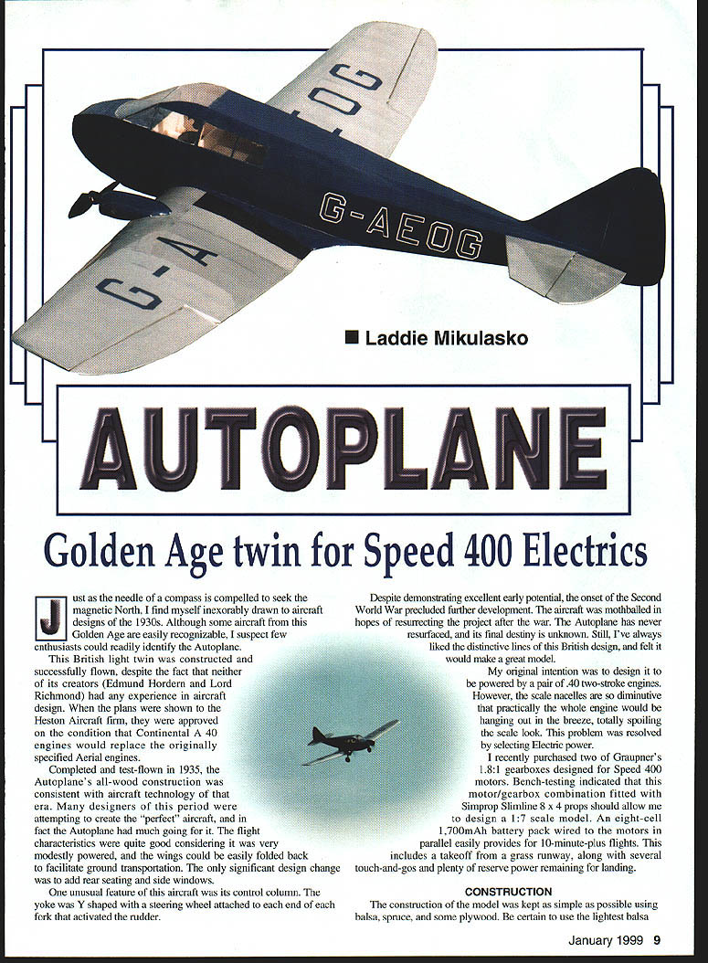
Just as the needle of a compass is compelled to seek the magnetic North, I find myself inexorably drawn to aircraft designs of the 1930s. Although some aircraft from this Golden Age are easily recognizable, I suspect few enthusiasts could readily identify the Autoplane.
This British light twin was constructed and successfully flown, despite the fact that neither of its creators (Edmund Hordern and Lord Richmond) had any experience in aircraft design. When the plans were shown to the Heston Aircraft firm, they were approved on the condition that Continental A40 engines would replace the originally specified Aerial engines.
Completed and test-flown in 1935, the Autoplane's all-wood construction was consistent with aircraft technology of that era. Many designers of this period were attempting to create the "perfect" aircraft, and, in fact, the Autoplane had much going for it. The flight characteristics were quite good considering it was very modestly powered, and the wings could be easily folded back to facilitate ground transportation. The only significant design change was to add rear seating and side windows.
One unusual feature of this aircraft was its control column. The yoke was Y-shaped with a steering wheel attached to each end of each fork that activated the rudder.
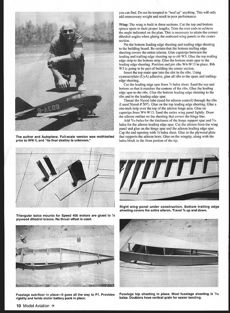
Despite demonstrating excellent early potential, the onset of the Second World War precluded further development. The aircraft was mothballed in hopes of resurrecting the project after the war. The Autoplane has never resurfaced, and its final destiny is unknown. Still, I've always liked the distinctive lines of this British design, and felt it would make a great model.
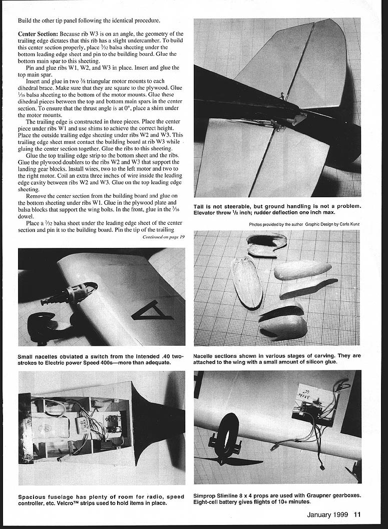
My original intention was to design it to be powered by a pair of .40 two-stroke engines. However, the scale nacelles are so diminutive that practically the whole engine would be hanging out in the breeze, totally spoiling the scale look. This problem was resolved by selecting electric power.
I recently purchased two of Graupner's 1.8:1 gearboxes designed for Speed 400 motors. Bench-testing indicated that this motor/gearbox combination fitted with Simprop Slimline 8 x 4 props should allow me to design a 1:7 scale model. An eight-cell 1,700 mAh battery pack wired to the motors in parallel easily provides for 10-minute-plus flights. This includes a takeoff from a grass runway, along with several touch-and-gos and plenty of reserve power remaining for landing.
Construction
The construction of the model was kept as simple as possible using balsa, spruce, and some plywood. Be certain to use the lightest balsa you can find. Do not be tempted to "beef up" anything. This will only add unnecessary weight and result in poor performance.
Wing
The wing is built in three sections. Cut the top and bottom spruce spars to their proper lengths. Trim the root ends to achieve the angle indicated on the plan. This is necessary to attain the correct dihedral angles when gluing the outboard wing panels to the center section.
Pin the bottom leading-edge sheeting and trailing-edge sheeting to the building board. Be certain the bottom trailing-edge sheeting covers the entire aileron. Glue capstrips between the leading- and trailing-edge sheeting up to rib W3. Glue the top trailing-edge strip to the bottom strip. Glue the bottom main spar to the leading-edge sheeting. Position and pin ribs W4–W13 in place. Rib W3 is going to be part of building the center section.
Insert the top main spar into the slot in the ribs. Using cyanoacrylate (CyA) adhesive, glue all ribs to the spars and trailing-edge sheeting.
Cut the leading-edge spar from 1/4-inch balsa sheet. Sand the top and bottom so that it matches the contour of the ribs. Glue the leading-edge spar to the ribs. Glue the bottom leading-edge sheeting to the ribs and to the leading-edge spar.
Thread the Nyrod tube (used for aileron control) through the ribs (I used Nyrod #507). Glue on the top leading-edge sheeting. Glue a one-inch strip over the top of the aileron hinge area. Glue on capstrips from W4–W13. Sand the entire wing panel lightly. Draw the aileron outline on the sheeting that covers the hinge line.
Add 3/16-inch balsa for the thickness of the hinge support spar and 3/16-inch balsa for the aileron leading-edge spar. Cut the aileron from the wing panel and glue on the hinge spar and the aileron leading-edge spar. Cap the end opening with 1/8-inch balsa sheet. Glue in the plywood plate that supports the aileron horn. Glue on the wingtip, along with the balsa block in the front portion of the tip.
Center section
Because rib W3 is on an angle, the geometry of the trailing edge dictates that this rib has a slight undercamber. To build this center section properly, place 3/32-inch balsa sheeting under the bottom leading-edge sheeting and pin to the building board. Glue the bottom main spar to this sheeting.
Pin and glue ribs W1, W2, and W3 in place. Insert and glue the top main spar.
Insert and glue in two 1/2-inch triangular motor mounts to each dihedral brace. Make sure that they are square to the plywood. Glue 1/16-inch balsa sheeting to the bottom of the motor mounts. Glue these dihedral pieces between the top and bottom main spars in the center section. To ensure that the thrust angle is at 0°, place a shim under the motor mounts.
The trailing edge is constructed in three pieces. Place the center piece under ribs W1 and use shims to achieve the correct height. Place the outside trailing-edge sheeting under ribs W2 and W3. This trailing-edge sheet must contact the building board at rib W3 while gluing the center section together. Glue the ribs to this sheeting.
Glue the top trailing-edge strip to the bottom sheet and the ribs. Glue the plywood doublers to ribs W2 and W3 that support the landing-gear blocks. Install wires—two to the left motor and two to the right motor. Coil an extra three inches of wire inside the leading-edge cavity between ribs W2 and W3. Glue on the top leading-edge sheeting.
Remove the center section from the building board and glue on the bottom sheeting under ribs W1. Glue in the plywood plate and balsa blocks that support the wing bolts. In the front, glue in the 3/16-inch dowel.
Place a 3/32-inch balsa sheet under the leading-edge sheet of the center section and pin it to the building board. Pin the tip of the trailing edge of W3 to the board. Slide the outboard wing panels onto the dihedral brace for a trial fit. Place the dihedral support under the W13 ribs. When satisfied with the fit, glue all of these pieces together. Add the triangular gusset between rib W3 and the trailing edge. Install the Nyrods to each aileron. On top of the center section, glue on balsa sheeting between ribs W2. On the bottom of the center section, cut out openings for the landing-gear blocks and glue the blocks to the ribs.
I used thin rubber strands to simulate landing-gear struts. To anchor the rear strut, I glued a 1/8 x 3/4-inch spruce between ribs W2 and W3 as shown on the plan. The side strut is attached to the landing-gear block.
Nacelles
Each nacelle is made from four hollowed balsa blocks. Be certain that the balsa blocks are slightly larger than the actual outline of the nacelle section. For the template, I made photocopies of the nacelle outlines and pasted them to each block, top and bottom. Using a jigsaw, cut around the perimeter of these templates. Repeat this procedure on all four blocks for each nacelle.
Once all four pieces are cut out, tack-glue the blocks together accurately. Carefully sand the corners of the nacelles to achieve the correct view shape. Referring to the drawing, you should be able to freehand-sand these parts accurately.
Once the desired shape has been achieved, take the nacelles apart. Remove most of the material on the inside, leaving approximately 1/8-inch thick walls, especially in the top halves. Reassemble the nacelles, using masking tape to hold the pieces together.
Mount the motors with their gearboxes. I used plastic tie wraps to secure the motors. Slide the nacelles over the motors so they fit onto the leading edge. If there is any binding, disassemble the nacelle and trim more material until it fits. The nacelles will be mounted to the wing after the wing and nacelles are covered.
Fuselage
Glue the top and bottom longerons to the fuselage sides. Glue the balsa doublers to the sides. The grain of these doublers is vertical to make it easier to bend the sides into place. Glue the subfloor in place; it goes all the way to the front bulkhead. The subfloor provides rigidity and holds the motor and battery pack in place. Fuselage top sheeting goes on next. Most fuselage sheeting is 1/16-inch balsa. Do not glue the cowl halves to the nose formers; leave them removable to allow access to the motors and gearboxes.
When assembling the fuselage, glue plywood doublers to these balsa doublers.
On the inside of each fuselage side, mark the locations of all formers. Glue on the 1/4 x 1/4-inch balsa upright where top former F14 is to be located, as well as the rear 1/8 x 1/4-inch balsa post.
Assemble the fuselage upside down. Clamp the fuselage sides together at the rear post, making certain that they are square to the building board. Glue in all formers between the sides, starting with former F7 all the way to F1. Again make sure that the centerline of each former is aligned with the center line on the drawing.
Glue in the balsa subfloor to formers F1, F2, F3, F5, F6, and F7. This floor has two functions: it gives the entire fuselage more rigidity, and it holds the motor battery pack in place. Since this floor extends all the way to the nose block, the battery will be less likely to buckle the nose of the fuselage in case of a hard landing.
Glue in the plywood plate that holds the tail skid. While the fuselage is still upside down, glue on the bottom sheeting between formers F1 and F4. Add the triangular-shaped plywood block that holds the tail skid. Glue the balsa sheeting on the bottom from F7 all the way back.
Flip the fuselage right-side up and glue the top sheeting between formers F1 and F3. Glue on all top formers F9 to F12. Glue 1/16-inch balsa sheeting to those formers as shown on the plan. Glue the nose block to former F1.
Sand the entire fuselage. Cut out the openings for the fin and stabilizer. Insert the U-shaped fork that joins the elevator halves. Insert, align, and glue the stabilizer to the fuselage. Insert and glue the fin in place. Inside the fuselage, glue in the two hardwood blocks that hold the wing bolts. If you wish, you may temporarily install all the equipment for a trial fit.
At last the model is ready for covering. Use your preferred method; my model was covered with an iron-on plastic. The registration numbers were cut from the same material.
After the model is covered, glue the windshield and the side windows in place using a transparent plastic. Install all the hinges and glue them in place (I used Sig's Easy Hinges). Even when cut in half, these hinges are plenty strong, since the loads on the control surfaces are light.
Solder the wires to the motors and install the motors into their mounts. Use a small amount of GOOP adhesive between the motor and the balsa motor mounts. Slide the nacelles over the motors and use a small amount of silicon glue to attach them to the leading edge of the wing. Should you need to remove the nacelles in the future you may easily do so by cutting through the silicon.
Install the landing gear. The struts on the landing gear can be made from thin wire or flexible plastic, since they are not functional. Glue in the tail skid. Install all the control horns and all the servos. The aileron servo is mounted horizontally to the 1/8-inch plywood plate.
The speed controller, receiver, receiver battery, and motor batteries are held in place with Velcro strips. A speed controller rated for 20 amps is acceptable for this motor/gearbox/propeller combination. An eight-cell 1,700 mAh SCR battery pack will provide for 15–18 minutes of duration if the model is flown in a scalelike manner. Position the motor battery pack inside the fuselage so that the model balances at the point shown on the plan.
Specifications
- Type: RC Sport Scale
- Wingspan: 62 inches
- Motors: Geared Speed 400s
- Functions: Throttle, elevator, rudder, aileron
- Flying weight: Four pounds
- Construction: Built-up
- Covering: Iron-on film
Flying
Check and adjust all flight controls. Set the elevator throw to provide 1/2 inch up-and-down movement. The rudder should have a maximum deflection of one inch. The ailerons should travel approximately 3/8 inch up and down; because the hinge line is near the top, this effectively provides differential aileron throw (more up than down).
After you have checked all flight and motor controls at home, it is time to head to the field to test-fly the model. Check once more to be certain that the model balances at the point shown on the plan (under the main spar of the wing).
Align the model into the wind and apply full power to the motors. The model will pick up speed quickly, but keep it on the ground to be certain that there is sufficient speed to provide a safe liftoff. Should the elevator feel overly sensitive, decrease the throw to suit your comfort level. Once it has been properly trimmed, the Autoplane can be flown safely at half throttle.
Laddie Mikulasko 7 Giffen Rd. Dundas, Ontario Canada L9H 6S1
Transcribed from original scans by AI. Minor OCR errors may remain.

