
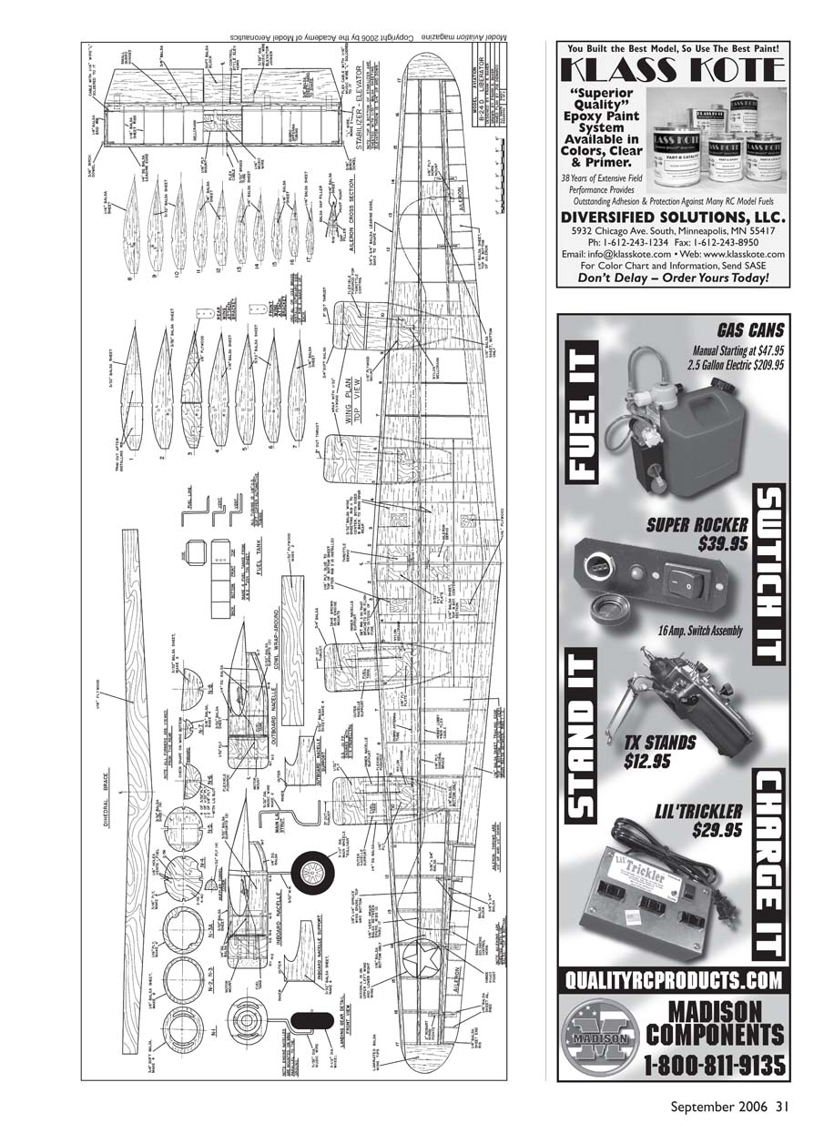
B-24
By Frank Baker
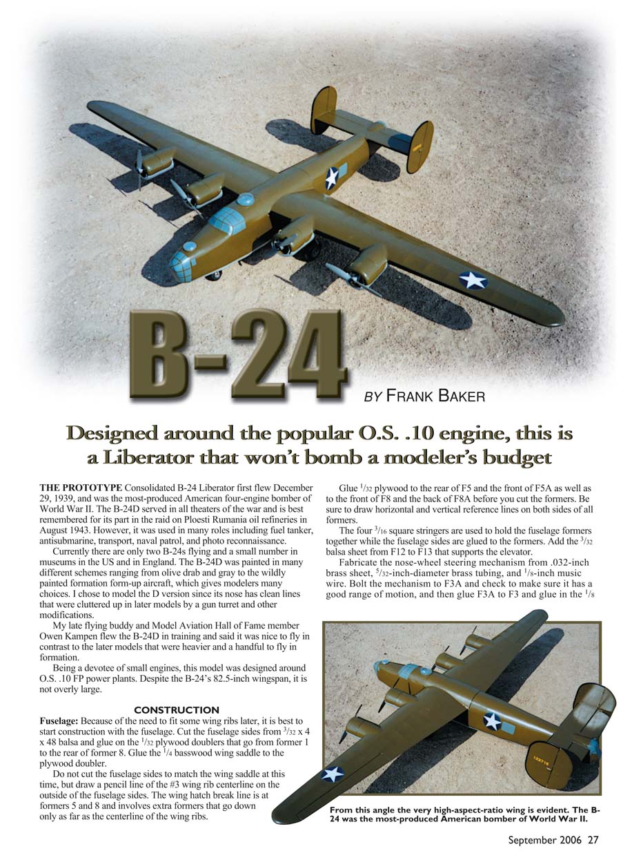
Designed around the popular O.S. .10 engine, this is a Liberator that won't bomb a modeler's budget.
THE PROTOTYPE
Consolidated B-24 Liberator first flew December 29, 1939, and was the most-produced American four-engine bomber of World War II. The B-24D served in all theaters of the war and is best remembered for its part in the raid on Ploiești, Romania oil refineries in August 1943. However, it was used in many roles including fuel tanker, antisubmarine, transport, naval patrol, and photo reconnaissance.
Currently there are only two B-24s flying and a small number in museums in the U.S. and in England. The B-24D was painted in many different schemes ranging from olive drab and gray to the wildly painted formation form-up aircraft, which gives modelers many choices. I chose to model the D version since its nose has clean lines that were cluttered up in later models by a gun turret and other modifications.
My late flying buddy and Model Aviation Hall of Fame member Owen Kampen flew the B-24D in training and said it was nice to fly in contrast to the later models that were heavier and a handful to fly in formation.
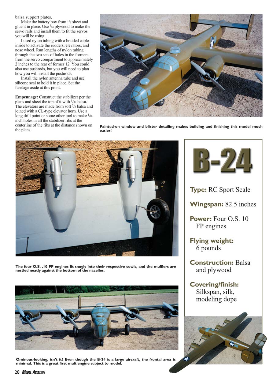
Being a devotee of small engines, this model was designed around O.S. .10 FP power plants. Despite the B-24's 82.5-inch wingspan, it is not overly large.
CONSTRUCTION
Fuselage
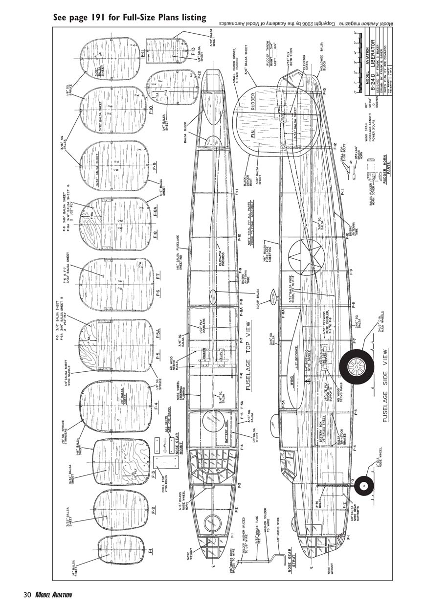
Because of the need to fit some wing ribs later, it is best to start construction with the fuselage. Cut the fuselage sides from 3/32 x 4 x 48-inch balsa and glue on the 1/32-inch plywood doublers that go from former 1 to the rear of former 8. Glue the 1/4-inch basswood wing saddle to the plywood doubler. Do not cut the fuselage sides to match the wing saddle at this time, but draw a pencil line of the #3 wing rib centerline on the outside of the fuselage sides. The wing-hatch break line is at formers 5 and 8 and involves extra formers that go down only as far as the centerline of the wing ribs.
Glue 1/32-inch plywood to the rear of F5 and the front of F5A as well as to the front of F8 and the back of F8A before you cut the formers. Be sure to draw horizontal and vertical reference lines on both sides of all formers. The four 3/16-inch square stringers are used to hold the fuselage formers together while the fuselage sides are glued to the formers. Add the 3/32-inch balsa sheet from F12 to F13 that supports the elevator.
Fabricate the nose-wheel steering mechanism from .032-inch brass sheet, 5/32-inch-diameter brass tubing, and 1/8-inch music wire. Bolt the mechanism to F3A and check to make sure it has a good range of motion, then glue F3A to F3 and glue in the 1/8-inch balsa support plates. Make the battery box from 1/8-inch sheet and glue it in place. Use 1/4-inch plywood to make the servo rails and install them to fit the servos you will be using.
I used nylon tubing with a braided cable inside to activate the rudders, elevators, and nose wheel. Run lengths of nylon tubing through the two sets of holes in the formers from the servo compartment to approximately 2 inches to the rear of former 12. You could also use pushrods, but you will need to plan how you will install them. Install the nylon antenna tube and use silicone seal to hold it in place. Set the fuselage aside at this point.
Empennage
Construct the stabilizer per the plans and sheet the top of it with 1/32-inch balsa. The elevators are made from soft 3/8-inch balsa and joined with a CL-type elevator horn. Use a long drill point or some other tapered tool to make 1/8-inch holes in all the stabilizer ribs at the centerline of the ribs at the distance shown on the plans.
For straight runs of nylon tubing, I prefer Du-Bro nylon antenna tubing that comes straight rather than in coils. Put the two sections of tubing in place and use silicone sealer to hold them. Slip the braided cable that is the length shown on the plans inside the tubes and center it.
Install a small Z link of 1/16-inch-diameter music wire in the rear arm of the nylon bellcrank and a Z link with a 2-inch or longer leg into the cross arm. Mount the nylon bellcrank on a plate of 1/16-inch plywood cut to fit between the two center ribs and slip it in place, with the horn facing the bottom of the stabilizer. Put the bellcrank in the neutral position as shown on the plans. Wrap the small Z link and the cable with fine copper wire, and solder them together.
Make the two rudder assemblies from 3/16-inch balsa and install the hinges. Glue the 1/32-inch plywood rudder-horn supports to both sides of the rudders. Make the rudder horns from .032 x 1/4-inch brass strips by making a 90° twist, and drill the rear 5/64-inch-diameter holes and the front 1/16-inch-diameter hole. Use 2-56 bolts to attach the horns to the inside of each rudder. Use an X-Acto knife to hollow out the rear spar and end rib of the stabilizer to allow for inward movement of the rudder horn.
Install a small, L-shaped, 1/16-inch-diameter music-wire link into the rudder horns. Drill a 3/16-inch-diameter hole in the vertical fins as shown on the plans. Push the vertical fin onto the peg and pin the assembly to the stabilizer. Note that the rudders tilt back slightly.
Check the rudders for roughly 3/4-inch right and left motion. If necessary, remove them and hollow out the stabilizer until they move properly. Put the nylon bellcrank and the rudders in their neutral positions. Wrap the rudder L-links and the cable together with fine copper wire and solder them. Use the bellcrank to move the rudders and position the 1/16-inch plywood plate to get the least friction, then glue the plate in place and solder the bellcrank nut to its bolt.
Make the rudder-horn covers from 3/32-inch balsa and pin in place. Check the rudder throw again. When the range is proper, glue on the covers and remove the rudder assemblies.
Install the nylon hinges in the elevators and stabilizer, and glue them in place. The 1/32-inch sheeting will be glued to the bottom of the stabilizer. You will have to cut a hole in the bottom sheeting to clear the bellcrank bolt and make a slot for the rudder pushrod. Glue on the balsa that fills the area between the two elevators. Slip the rudder horns on the L-links and solder a small glob on the end of the L. Glue the vertical fins to the stabilizer.
Cut two lengths of braided cable that will reach from the elevator hinge line to the middle of the servo rails. Use a short length of 3/32-inch-diameter brass tubing as a joiner, and solder one cable to the rudder bellcrank Z link. Solder a Z link to the second length of cable and insert the Z link in the elevator arm.
Completing the fuselage empennage installation: Slip the rudder and elevator cables inside their respective tubes and pin the empennage in place. From the servo compartment end, use the cables to move the rudders and elevators to see if you get the full range of motion. You can slide the nylon tubes a bit if necessary to get clearance. When things are proper, use some clear silicone sealer to hold the nylon tubes to the formers. Remove the empennage and set it aside.
Slip a length of nylon tubing through formers 4, 5, and 6. Solder a 1/16-inch-diameter music-wire Z link to a length of cable, insert it into the steering arm of the nose wheel, and feed the cable through the nylon tube. Mount the rudder servo and add a threaded connector and quick link at the servo end of the cable.
Hook up your radio and use the transmitter to run the nose wheel right and left. Make sure it is properly coordinated with the rudder movement.
Put a few small spacers of 1/64-inch plywood between F5 and F5A, but do not glue them. Place two or three very small spots of glue between the outer edges of F5 and F5A to hold them together. Do the same for F8 and F8A, but do not use spacers.
Install the 1/8-inch square spruce stringers on the top and bottom of the fuselage. I would precut the three top stringers at the slit between F5 and F5A and between F8A and F8. The top and bottom of the fuselage will be sheeted with 1/16-inch balsa, using a 4 x 48-inch sheet for each quarter of the fuselage.
For the sheeting select medium A-grain balsa that bends well across the narrow dimension of the sheet. Making trial pieces from thin poster board will facilitate the correct cutting of the balsa sheets. Once a balsa sheet fits, it can be glued in place using aliphatic resin glue. Be sure to mark the wing-hatch separation lines on the top sheeting so you can find the slit later on.
Once all the sheeting is in place, roughly carve the nose and tail blocks to shape and glue them in place. Now you can carve and sand the nose and tail blocks to their final shape. Drill a 5/8-inch-diameter hole in the nose block for containing the lead nose weight (if needed).
Cut a block for the cockpit area and fit it between F3 and F4. Rough-cut it to shape, hollow it to roughly 1/4-inch thickness, and glue it in place.
To free the wing hatch, use an X-Acto knife with a new blade. Slip it between the plywood faces of F5 and F5A, and work it around from one side to the other. Do the same thing at the interface of F8A and F8. Use a razor saw to cut along the pencil line of the wing-rib centerline on the side of the fuselage. You should be able to lift the wing hatch out of the fuselage.
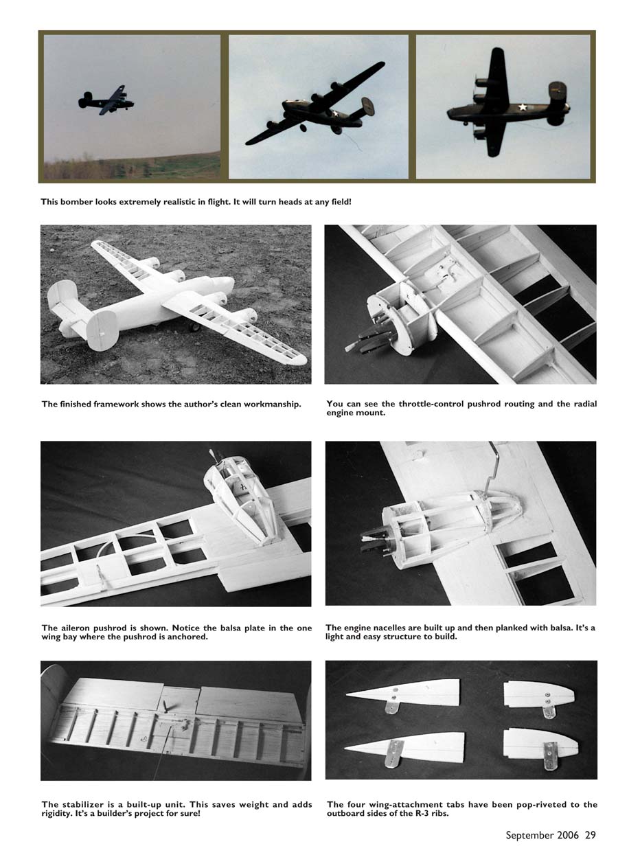
The fuselage construction may seem light to some builders, but it is extremely rugged once completed.
Wing
Take the wing-rib drawings to your local copy shop and make two copies of the ribs. Cut them approximately 1/8-inch oversize from the paper, lightly spray contact adhesive to the back of the paper, and stick the ribs to the balsa sheet. Note that rib 3 is made from 1/8-inch plywood. Do not use light plywood (poplar) for this rib.
Drill the 1/8-inch-diameter holes in ribs 1–9 for the motor-control tubing and ribs 1–3 for the aileron control tubing. Once the ribs are cut out and drilled, remove the paper. Save a rib-3 template for later use.
With a fine-point felt-tip pen, draw the centerlines on both sides of all the ribs. Draw vertical lines on ribs 12–16 at the front of the rear wing spar and at the back of the aileron LE.
Cut the four wing spars—roughly 1/2 inch longer than shown on the plans—from 1/8 x 1/4-inch spruce or basswood. The wings will be built upside down, so pin the top spar for the right wing to the plans. Slip all the ribs (top down) except rib 3 onto the spar. Starting from the root rib, glue the rib to the spar with slow-drying glue.
On lengths of scrap balsa mark the height of the rib centerline at the back edge of the spar. Check the front and rear ends of the rib-centerline marks to see that they are the same height. Put chunks of scrap balsa under the front and rear parts of the rib to help hold the rib's position, and then pin the rib in place. Repeat this process for each rib from the root to tip rib. As you add each rib, sight the front and rear centerline marks to see that they form a straight line and that all the centerlines are parallel.
Install the 3/8 x 1-inch leading edge (LE). You may want to slightly taper the LE before gluing it in place. Glue on a 41-inch length of 1/16 x 1-1/2-inch balsa sheet to the rear of all the ribs except rib 17 and use a square to make sure that this sheet ends at the wing trailing edge (TE) per the plans.
From rib 10 to 17 glue 1/16-inch vertical-grain balsa shear webs between each pair of ribs. Make sure the upper edge of the web is flush with the lower edge of the wing-spar slot. Glue the bottom 1/8 x 1/4-inch spruce spar to the ribs and the webs. Glue the LE 3/32-inch balsa sheet that goes from the root rib to rib 11.
When the glue is dry, remove the wing panel from the building board and use a razor saw to cut ribs 12–16, first at the rear of the aileron LE and then at the front edge of the rear wing spar. Cut a 3/16-inch-square slot in rib 11 to accommodate the rear wing spar stub.
Cut a 16-inch length of 3/8 x 3/4-inch balsa for the aileron LE, and taper the thickness from 3/8 inch at the root to 3/16 inch at the tip. Pin 1/16-inch balsa spacers between this piece and the 3/16 x 3/4-inch rear wing spar. Trim the 1/16-inch bottom TE to accommodate the aileron LE. Glue the spar assembly to both parts of the ribs, making sure that the rear wing spar is centered and that the centerlines of all the ribs form a straight line. The rear spar should protrude approximately 3/32 inch above and below the ribs.
Glue the 1/16 x 1/4-inch balsa capstrips on ribs 12–17. Install the bottom 1/16-inch sheet that goes from the root rib to rib 17. From 1 inch outside of rib 10 to 3/32 inch inboard of rib 9, draw a line on the front of the wing's LE that corresponds to the centerlines marked on the ribs, and then use a small plane to rough-shape the LE. Set the right wing aside and build the left panel in the same sequence.
When both wing panels are constructed, make the dihedral brace from 1/16-inch plywood. Find a hacksaw blade that will make a 1/16-inch-wide cut, and make a vertical slot in ribs 1–10 that is flush with the back of the upper and lower wing spars. The dihedral brace should slip into the slot.
Slip both wing panels onto the dihedral brace and check to make sure the top and bottom edges of the dihedral brace are flush with the tops of the spars. Also make sure the number-1 ribs of the two panels fit together properly.
When everything fits, glue the dihedral brace into the two panels using slow-drying glue. Be sure the rear sections of the ribs are flush with the tops of the spars. Use an incidence meter to make sure the wing is straight, with no washout or washin. Stand off and eyeball it to see that it is correct.
When the glue is dry, install all the 1/16-inch balsa sheeting on the bottom of the wing that goes from 3/4 inch outboard of the left rib 6 to outboard of rib 6 on the right wing. Glue the capstrips on the bottoms of ribs 7 and 8. Between F5 and F8 trim the fuselage sides down to the wing saddle.
Set the fuselage on the workbench. Use heavy objects to hold it with the fuselage sides vertical to the workbench and the top of the fuselage at 0°. Place the wing in the saddle and make sure the wing is perpendicular to the centerline of the fuselage, the wingtips are the same distance from the surface of the workbench, and the wing is at 2° incidence. It may take carving and sanding the wing saddle, F6, and F7 to accomplish a proper fit and positioning of the wing, but it is critical.
Once everything is aligned properly, use a soft pencil to mark where the outside of the fuselage meets the wing. Draw the line on both panels from LE to TE.
Make the four wing-attachment tabs from .050-inch aluminum or .032-inch brass, and pop-rivet them to the outboard sides of rib 3. Measure where the tabs should go through the bottom wing sheeting, and cut narrow 3/16-inch-long slits at the pencil lines that were previously drawn on the sheeting. Slip the number-3 plywood ribs in position with the tabs through the slits.
The metal tabs should fit snugly against both sides of the fuselage. Modify the slits until this is achieved, and then glue the two ribs in place. Glue the four 1/16-inch plywood plates inside the bottom wing sheeting and up against the outboard sides of the tabs. Use a pencil to mark the holes of the metal tabs on the fuselage sides and drill 5/64-inch-diameter holes in the basswood wing saddle. Mount 2-56 blind nuts on the inside of the saddle. Use 2-56 x 1/2-inch socket-head bolts to hold the wing onto the fuselage.
Nacelles and Throttle Controls
Cut the four N4 firewalls from 3/16-inch birch plywood, and drill the holes for the Dave Brown Products 15/19 engine mounts. Install the 4-40 blind nuts at the back of the firewall. I use the 15/19 instead of the 09/10 mounts because they allow you to move the engine a bit farther forward from the firewall.
Drill the holes for the throttle control. Do not drill the three 1/8-inch holes for the fuel-tank pipes until the tanks have been fabricated. Drill the holes for the 2-56 cowl bolts, and install the blind nuts at the back of the firewall.
Feed a 2-56 bolt through a piece of 1/16-inch plywood and bolt it to the lower hole. Use a grinding wheel to cut the bolt off flush with the back of the blind nut. Make eight of these bolts and save them.
Coat the fronts of the firewalls with thinned epoxy to fuel-proof them. Install the engine mounts with 4-40 bolts and make sure they pull the blind nuts into the plywood. Use a grinding wheel to cut off the 4-40 bolts flush with the backs of the blind nuts.
Build the four fuel tanks from K&S #254 tin sheet. Cut the four long strips and eight side caps per the plans. Note that the fuel line and vents go through holes drilled in the top of the tank. Bend the four long tin strips per the plans, and solder the tab that bends over the top of the rear end of the tank.
Use automotive 1/8-inch-outside-diameter soft-copper tubing to make one set of vents and a fuel line. Slip them through the holes in the top of a tank and spot-solder them in place. Slide the copper tubes through the holes in a firewall. You may have to use a small round file to slightly enlarge the holes, but do not make them oversize.
Once the tubes have slid through the firewall, make sure the tank is horizontal and parallel to the centerline of the nacelle. Take note of any changes in the bends of the tubes and any changes in length that you feel are necessary. Make three more sets of fuel lines and vents. Final-solder all of the copper tubing into the tanks.
Custom-fit the sides of the tanks to each individual tank. When the tanks are all soldered, pressure-test them under water and check for leaks.
Install all four tanks in the firewalls, and use epoxy around the copper tubes at the front and rear of the firewall. Put some glue between the firewalls and the fronts of the tanks.
Mark the centerline of each nacelle on the LE and draw a line to the bottom TE that slants 1-1/2 inches toward the root rib. Draw two lines parallel to this line to locate the nacelle supports. Cut the eight nacelle supports from 3/32-inch balsa and draw a centerline on each.
Set the wing at 2° incidence and then fit the engine-nacelle supports so that their centerlines are at 0°. Stand the wing on its TE and support it so that the main wing spars are parallel to the workbench. Glue on the nacelle supports at their respective 1-1/2-inch out-thrust lines. Notice that forward of the LE the inside supports for each nacelle are slightly longer than the outside supports.
When the glue is dry, place an incidence meter across the fronts of the supports and check for 3° out-thrust. This measurement is critical; the 3° is the secret to good engine-out behavior. Install former N5 in each nacelle.
Block up the wing on the workbench with the 2° incidence established and the wingtips the same distance from the bench top. Use an incidence meter to make sure the front edge of each nacelle support is perpendicular to the workbench; i.e., the engines are at 0°. Epoxy the firewall assemblies to the nacelle supports and check again to ensure that everything is aligned properly before the glue sets. When viewed from the front, the firewall's horizontal centerline is parallel to the ground—not to the wing dihedral.
Mount all four O.S. .10 FP engines on their mounts. Cut the four 1/16-inch plywood bellcrank mounting plates that fit between ribs 5 and 6 and between ribs 9 and 10. Mount a 90° nylon bellcrank on each plate, and fit the assemblies in the wing; do not glue them. Note that all pairs of bellcranks point toward their respective wingtips.
Make the 3/32-inch plywood engine-control servo-mounting plate. Install two 1/16-inch threaded ball links on the servo wheel and mount the servo on the plate. Cut out the section of rib 1 as shown on the plans, and glue in the mounting plate. Make sure the ball joints line up with their respective rib holes. Use your radio to put the servo in neutral, and make sure the two ball links form a vertical line.
Install the four lengths of nylon antenna tubing in the wing-rib holes. Solder the brass couplers that come with the ball links to one end of each of the two lengths of cable that go from the servo to the outer nacelles. Install the nylon ball connectors on the couplers, feed the cable through the nylon tubes, and attach the nylon connectors to the servo ball links.
Use the radio to move the servo to its limits of rotation and make sure the nylon tubes near the servo do not interfere. Insert lengths of nylon tubing from the bellcranks through N2 and the firewall.
Make eight short Z links from 1/16-inch-diameter music wire. Solder four of them to lengths of cable that will be the throttle controls. Insert the Z link into the bellcrank arm and run the cable through the nylon tube to the engine.
With the bellcrank held in the neutral position shown on the plans and the throttle arm in midrange, cut the cable to the approximate length. Cut roughly 3/16 inch off the hollow and threaded ends of a brass coupler, and put on a nylon quick link. Install the quick link on the throttle arm and the cable.
Move the bellcrank back and forth to make sure the nylon tube does not restrict the motion, and trim the tube as necessary. Cut the cable to its final length and solder the coupler to it. Things will go a bit easier if you do one engine at a time then the remaining three.
Insert the remaining Z links in the rear-facing arms of the bellcranks with the bottom part of the Z link pointing toward the wingtips. With everything in the neutral position, bind the Z links to the cable with fine copper wire. Shine a flashlight into the throttle body to make sure the high and low positions are the same for all four engines.
You may need to slide the Z links a bit to align the bellcranks to the position shown on the plans before soldering them to the cable. Use the radio to run the throttles to their fully open and closed positions, making sure the nylon tubes do not interfere and that the angle of the bellcrank mounting plates does not cause friction.
It may be necessary to allow the ends of the nylon tubes closest to the bellcranks to move a bit in the adjacent wing ribs. The same is true of the ends near the aileron servo. When everything is moving properly, glue the four mounting plates in position and use silicone sealer to hold the nylon tubes in place. The throttles should be set like those in a sport airplane. Low throttle with high trim should give low idle. Pulling the trim to full low should kill the engine.
Ailerons
Cut the bottom 1/16-inch TE along the slant line at rib 11 and inboard of rib 17. Pull the aileron free from the rear wing spar. Install the 3/8-inch hinge blocks. Mark the positions of the hinges on the LE of the aileron and the rear wing spar, and drill holes for the 2-inch Robart hinge points. Use scraps of 1/16-inch to make the aileron ribs that fit between the existing ribs.
Add 1/8-inch ribs at the root and outer ends of the aileron. Use 1/16-inch sheet to completely cover the top and bottom of the aileron. Put 3/32-inch balsa on the outboard rear side of rib 11 and taper it to match the angle of the bottom sheeting. Sand the aileron LE to its final shape.
Make 3/16-inch square holes in the aileron LE far enough back to place the hinge pin where shown on the plans. Glue the hinge points into the aileron. Cut a small square of 1/16-inch plywood and mount a small control horn on it. At the location shown on the plans, cut out enough of the aileron LE and rib to fit the plate flush with the bottom of the aileron, and glue it in place.
To temporarily attach the ailerons to the wings, push the front parts of the hinge points into the rear spar blocks, leaving a 1/16-inch space between the wing and the ailerons. Pin the ailerons in the neutral position.
Make the aileron-servo mounting plate from 3/32-inch plywood, and attach the aileron servo to it. Cut out rib 1 per the plans and fit the servo assembly between the left and right number-2 ribs.
Slip Hobby Lobby nylon tubing (item 805) through the holes in the ribs from the left wing to the right wing. The nylon tubing should end approximately 1 inch from each aileron horn. Cut a 1/8 x 3/8-inch slot in the 1/16-inch sheet that fits between the bottom capstrips of ribs 14 and 15. Slip the sheet over the nylon tubing and glue it in place.
At the center of the wing make sure the tubing is level between the number-2 ribs. Adjust the rib holes until the tubing is level, and then cut out the center-section of the nylon tubing per the plans.
Cut approximately 3/16 inch from the hollow and threaded ends of a brass coupler, and solder it to one end of the flex cable. Attach a nylon quick link to the coupler. Insert the braided cable in the nylon tubing from the left to the right aileron horn, and clip the quick link onto the left aileron horn. You may have to trim the nylon tubing so that the aileron has full downward throw. Put the ailerons back in neutral.
At the right aileron horn, cut off the cable to fit a threaded coupler and a quick link, and then clip it onto the right aileron horn. Insert the cable and solder the right coupler to the cable. Make a small Z link from 1/16-inch-diameter music wire and insert it in the upper arm of the aileron servo. Wrap the link and cable with fine copper wire, and solder them together.
Use silicone sealer to glue the nylon tubing to the inside of the 1/16-inch plates between ribs 14 and 15. Remove the pins holding the ailerons; they should remain at neutral. Use your radio to cycle the aileron servo. There should be 1/2-inch up and down throw measured at the root end of the aileron.
When the engine and aileron controls function properly, the remaining 3/32-inch and 1/16-inch sheet can be glued in place over the top of the wing. The remaining capstrips and the wingtip blocks can be installed after cutting off the wing spars outboard of rib 17. Install the balsa aileron gap strips.
Completing the Nacelles
The two outer nacelles will be finished first. Glue formers N7 and N8 in place. Pay attention to the slant of the formers, which should match that of the bottom of the wing.
Cut the side and bottom stringers from 1/4-inch balsa sheet and glue them in place. Use scrap 1/8-inch balsa to make stringers that fit between F8 and F7 that are halfway between the bottom and side 1/4-inch stringers.
Sheet the nacelle with 3/32-inch balsa. I use thin poster board to get a rough idea of how to fit the sheeting to the nacelle. Fit poster board from the middle of the top stringer to the middle of one of the side stringers. Do the same to the other side. When the poster board fits reasonably well, use it as a pattern to cut the 3/32-inch sheet.
Wet the sheets with hot water to which ammonia has been added, and then fit both balsa pieces to the top of the nacelle. Taper the bottom sides of the rear parts of both pieces so that they smoothly fit the curvature of the top of the wing.
When both pieces fit properly, glue them in place. When the glue has dried, trim the sheets along the centerline of the side stringers. Repeat this process for the two bottom pieces, gluing on one side at a time.
The two inner nacelles are built in the same fashion, but they also contain the landing-gear assemblies.
Bend the main landing gear from 5/32-inch-diameter music wire. Trace N6 onto the various thicknesses of plywood as called out on the plans, and cut them approximately 1/8 inch oversize. Cut the slot in the 1/8-inch and 1/32-inch plywood pieces, and make sure the landing-gear strut fits in the slots, the axles point toward the fuselage, and the slant of the former matches that of the bottom of the appropriate wing panel.
With the landing-gear struts inserted in the slots, epoxy the two inner pieces and the two outer 3/32-inch plywood pieces together and clamp them until the glue sets. Trace N6 onto the laminated plywood and cut it to shape.
Block up the wing upside down on the workbench with a negative 2° incidence and both wingtips touching the workbench. Place the gear assembly on the bottom of the wing and make sure the landing-gear leg is perpendicular to the workbench, the axle is parallel to the workbench, and the axle is parallel to the line of the main spar. Trim the plywood until it fits snugly against the bottom sheeting. When the assembly can be aligned properly, epoxy it in place and check its position once more before the glue sets.
Cut and install the 1/4-inch stringers and former N7. Note that the side stringers terminate against the bottom of the wing, and the bottom stringer butts up to both sides of N6. Cut some scrap 1/8-inch balsa to add the stringers between N6 and N7.
Use the procedures described previously to sheet the nacelles. Remove a half-ellipse from the sheeting at the half-round muffler cutout on the firewall. Glue a piece of 1/32-inch plywood bent into the cutout, and epoxy it in place. Trim any excess above the balsa sheeting. When the muffler is mounted, there should be approximately 1/16 inch clearance between the plywood and the muffler.
Cowls
Since the B-24's cowls have straight lines, they can be constructed from wood. Cut cowl formers N1, N2, N3, and N3A per the plans, and use a pencil to mark the horizontal and vertical centerlines.
Make the four 1/32-inch plywood cowl strips. Glue N2 to the back of N1 and make sure there is at least 1/32 inch difference between the outer edge of N2 and the outer edge of N1. N2 is the smaller of the two formers.
Glue N3 to the front of the 1/16-inch plywood N3A and drill the 5/64-inch-diameter holes in N3A. Place a piece of kitchen plastic film on the front of the firewall and bolt formers N3–3A to the firewall with the short 2-56 socket-head bolts.
Wrap the 1/32-inch plywood strip around formers N2 and N3 with the overlap on the right-hand side, even with the centerline of the engine mounts, and check the fit. Repeat this process using slow-drying glue, using masking tape to hold the plywood tight to the formers and the overlap together.
Sight the cowl from the front and make sure its centerline is vertical to the ground and that the cowl is not twisted. To remove the cowl when the glue is dry, access the two 2-56 bolts through the top or bottom of the oil-cooler slots in N1. Make the remaining three cowls in the same manner.
Mount the O.S. .10 FP engines on the mounts, and locate the cutouts for the cylinder head, muffler, and needle valve. Notice that there is a strip of cowl between the cylinder head and the muffler. Cut the cylinder hole straight back to N3. Also drill two small holes so that a screwdriver can be used to attach the mufflers to the engines after the cowls have been installed.
Cut and sand N1 to the shape the plans show. The inner sections of the oil-cooler slots are weak and should be coated with cyanoacrylate glue, which will stiffen them considerably. You will need to remove some of the inside of N1 so that the throttle arms have full motion.
Finishing the Fuselage
Mount the wing on the fuselage and attach it with the four wing-tab sheet-metal screws. Block up the fuselage and wing so that the top of the fuselage is at 0° and the two wingtips are the same distance from the workbench. Slip the elevator and rudder cables into their respective nylon tubes, and place the tail assembly on the top of the two fuselage sides.
Use an incidence meter to set the stabilizer at 0°. Determine how much of the fuselage sides should be removed so that the top of the stabilizer at the hinge line is flush with the top of the fuselage. After the stabilizer fits, ensure that it is perpendicular to the fuselage centerline.
Sight from the front of the fuselage to make sure the tips of the stabilizer are the same distance above the wing. If they are not, trim the fuselage sides slightly to fit, but do not overtrim. You may want to glue some 1/4-inch balsa inside the fuselage sides to provide better support for the tail assembly.
Cut the rear turret fairing from 1/2-inch balsa and fit it to the balsa that fits between the two elevators and up against the rear turret. Cut the fuselage fairing to the front of the stabilizer from 1/4-inch balsa and trim it to fit, then install the fairings.
The last bit of construction is to fit the hatch to the wing. Lay the number-3 rib template on the rib centerline that was drawn on the section of fuselage that was removed along with the hatch. Cut the sheeting at the top contour of rib approximately 1/8 inch closer to the centerline. Slide the hatch down between formers 5 and 8. The top of the hatch should protrude above the top line of the fuselage.
Use a soft pencil to trace the contour of the top of the wing on both sides of the hatch. Carefully trim in stages up to this line until the hatch fits the wing and is flush with the top of the fuselage. When this is achieved, glue the hatch to the wing and the construction is finished.
Covering and Finishing
Being of the old school, I like to use tissue, silk, and aircraft dope to finish models. I put medium-weight Silkspan on the fuselage and empennage. I used silk on the wings. However, Mylar film can be nice to use since the appropriate colors are readily available.
I doped the cowls inside and out. I sprayed the upper surfaces with olive drab and the bottoms with gray. I used an early-war version of the U.S. insignia, which was blue circles with white stars cut from trim film.
I created the window frames for the nose, cockpit, and rear turret by laying down 1/16- and 3/32-inch tape and then spraying the exposed areas with dark-gray dope. When the tape is removed, the window frames are the correct colors.
I carved forms for the astrodome and top turret from basswood and mounted them on a dowel in a baseplate. I heated .020-inch acetate sheet to 250°F in the oven and pulled it down over the forms. This is even easier if you have a vacuum box. I did not bother to mount guns in the turrets since they are the first things to get broken off.
Flying
Balance the assembled model with radio, servos, and batteries installed, and check to see if it balances at the point shown on the plans. If it does not, put a mixture of epoxy and lead shot in the vertical 5/8-inch-diameter, 2-inch-deep hole in the noseblock. Add enough lead in the hole to achieve the CG shown on the plans. Then plug the hole and paint the plug gray.
Since the fuel-tank vents are inaccessible, put lengths of silicone fuel line on them that reach approximately 1/2 inch beyond the front of the cowl. They can be tucked back into the cowl for flight. Be sure to flex both ailerons up 1/8 inch as measured at the aileron root rib.
Each time I fly the B-24 I am asked how I get all those engines started. My technique is to start each engine, run it for roughly 30 seconds, and then shut it down. Then, starting from the left engine, each engine will fire up with a single flip of the propeller.
I have learned that the B-24 performs best with Master Airscrew 8 x 4 propellers. The model steers nicely on the ground, takes off extremely quickly, and should be climbed at a shallow angle. Once in the air, it flies rapidly, has a level stance, and looks realistic.
Because of the short coupling, it is important to coordinate rudder and ailerons when making turns. To land, set up a wide rectangular pattern, and on the base leg throttle back enough to set up a moderate rate of descent. After passing over the edge of the flying field on final, pull the power back to idle and let the model glide in. Just before touchdown, give a bit of up-elevator to flare and land on the main wheels.
Because of the short nacelles, the fuel tanks are rather small. Time them on a ground run and then try to land well before the fuel runs out.
If an engine quits in the air, the B-24 will keep flying—a benefit of the 3° engine out-thrust. However, it behooves you to land as soon as is practical.
Frank B. Baker [email protected]
Transcribed from original scans by AI. Minor OCR errors may remain.

