

Bandit
One day in the fall of 1998 I had a call from Ken Oliver, the whiz who produces a variety of the high-tech fuselage systems used by modelers around the world. Ken wondered if I'd seen the F1J model that Evgeny Verbitsky (top competitor in F1C power) was showcasing at the just-completed Sierra Cup competition.
What interested Ken was the fuselage, with its pop-bottle-like taper and small-diameter tailboom. Ken felt that this configuration might be stronger and lighter than the fuselage we were using. He speculated that the very small tail-end diameter (about .375 inch) might be a problem, and he asked if I could machine a Variable Incidence Tailplane (VIT) frame small enough to work.
About a week later he had the prototype. (I make and sell VIT systems for competition models, ranging from ½A–F1J through the larger A, B, and C classes.)
The weight of the new unit—including the glide post, adjuster nut, and stab "keeper" button—was just 1.9 grams, and the unit doesn't require tubing guides or other plumbing to make it work. With my commitment to offer these for sale, Ken decided to go ahead with the new fuselage.
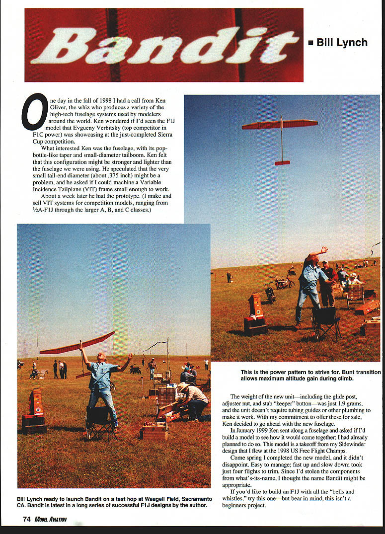
In January 1999 Ken sent along a fuselage and asked if I'd build a model to see how it would come together; I had already planned to do so. This model is a takeoff from my Sidewinder design that I flew at the 1998 US Free Flight Champs.
Come spring I completed the new model, and it didn't disappoint. Easy to manage; fast up and slow down; took just four flights to trim. Since I'd stolen the components from what's-is-name, I thought the name Bandit might be appropriate.
If you'd like to build an F1J with all the "bells and whistles," try this one—but bear in mind, this isn't a beginner's project.
Specifications
- Type: FF F1J
- Wingspan: 73 inches (flat)
- Engine: AD .06 two-stroke
- Construction: balsa and composites
- Flying weight: Approx. 9.5 ounces
- Covering/finish: Oracover
Construction
Fuselage
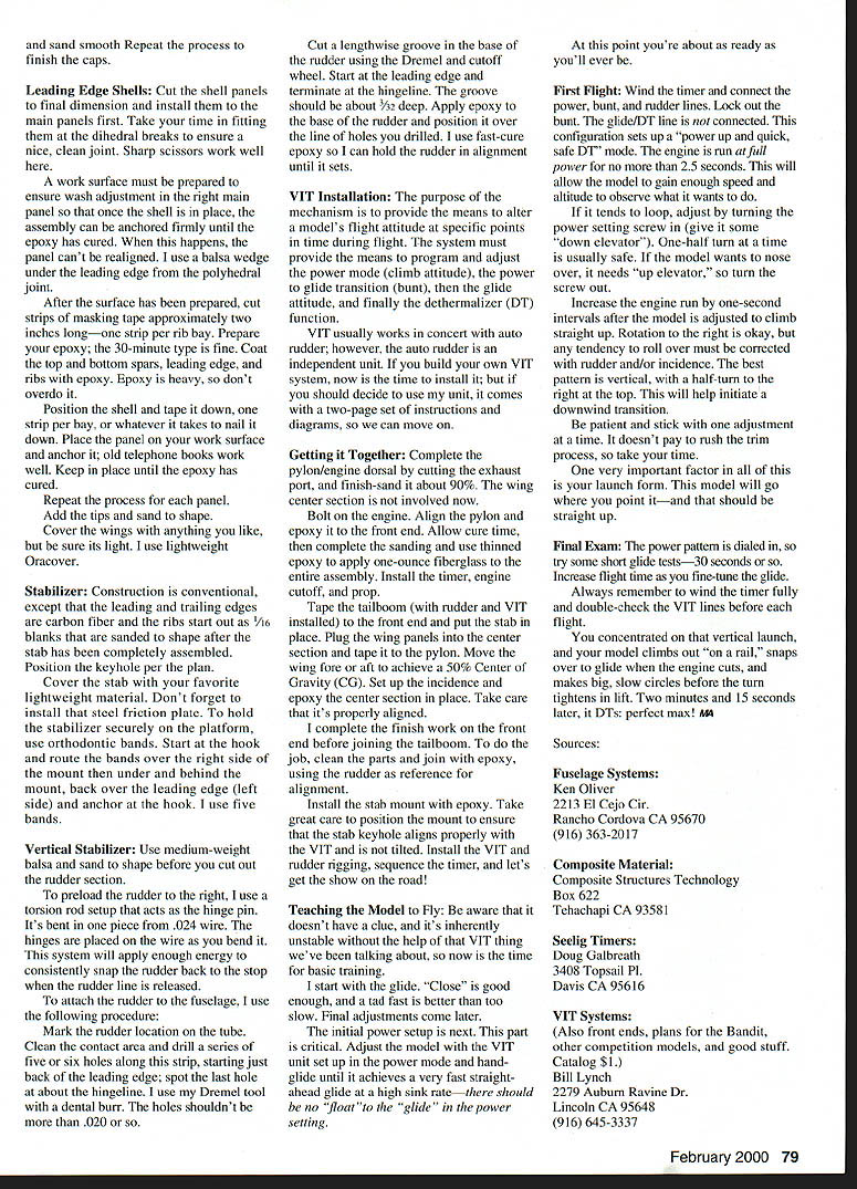
The main fuselage parts are the carbon-fiber front end and the aluminum tailboom. Start by cutting the hole for the timer mounting plate. A Dremel® tool with a cutoff wheel works for this (and for any cuts you will make in the aluminum tube). Complete the timer installation before moving on to the pylon.
Build the pylon per the plan, then fit it to the tube by taping a strip of sandpaper on the tube lengthwise and sanding the curvature into the base of the pylon. Don't epoxy in place at this time.
Fit and epoxy the firewall in place (I use 3M® DP-460, an industrial-grade epoxy), but be sure it is properly oriented with respect to the mounting hole pattern and side thrust and downthrust settings, and be sure all surfaces are clean before applying epoxy.
Note: The plans show the AD .06 engine, but the new Cyclon .06 will fit the same mounting holes.
Wing
Lay out the leading and trailing edges. Insert and glue the ribs (use cyanoacrylate glue) by trimming at the trailing edge. Omit ribs at the dihedral joints. Install the laminated top spar. Remove the panel from the work surface and install the bottom spar. Tip panel ribs are marked and notched for spars after they are installed to ensure that they meet main panel spars correctly.
Plank the bottom of the main panels per the plan, leaving the top open to allow positioning of the joiner sockets.
Prepare the center section blank per the plan, then fix to a firm work surface. I work on tempered glass, but any good, firm surface will do. Fix the blank with double-stick tape or small drops of CyA.
Cut the female section of the joiner into three pieces and plug the sections to be installed in each wing panel with 1/16 balsa. This is to prevent CyA or epoxy from migrating into the joiners; should this happen, you will have to tear the joiners out and start over. Prepare the .093 aluminum tubing sections in the same manner.
Insert the male portion of the joiner through the three larger tubes. Position the center piece into the predrilled center section blank, then position each wing panel in place. (The holes in the root ribs may have to be enlarged to allow for dihedral adjustment.) Block up each wing panel at the tip until the required dihedral is achieved.
With the mains correctly set and held in place, tack the joiners in place with thick CyA. Be very careful to avoid gluing the joiners together. Install the secondary joiners (tubing and steel pin) using the same procedure. Reinforce the tubing with balsa.
Separate the sections and box in the joiners in each panel, leaving a small opening parallel to the top spar. Through this opening, fill the area around the boxed-in socket with epoxy mixed with carbon filler.
Complete the planking. Sand and cover the planked area with one-ounce fiberglass and epoxy. Sand to finish.
Go back to the center section. Carve and sand to mate with the wing panels. Leave the bottom of the section flat so it will mate easily with the pylon.
Install the end-grain fillers between the ribs and join the main and tip panels. A very strong dihedral brace can be made by inserting strands of carbon-fiber tow to extend through the joint to the next rib. Fix the tow in place to the I-beams with fast-cure epoxy. This creates a composite brace that won't fail.
To install ribs at the dihedral joints, cut in two parts and trim to fit. Half-ribs are installed now. Sand the panels so all joints are smooth.
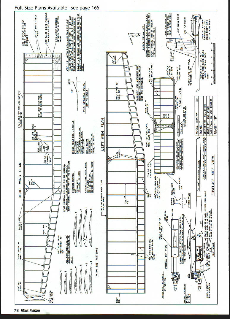
Those little carbon-fiber rib caps go on now. Cut them from stock that's several inches wide and about half an inch longer than needed. Cut the strips about 1/32 wider than the rib thickness.
I usually start on the bottom surface. CyA each cap, starting at the leading edge of the spar. The strip should extend well past the trailing edge. After the caps have been installed, simply break off the ends, and sand smooth. Repeat the process to finish the caps.
Leading Edge Shells
Cut the shell panels to final dimension and install them to the main panels first. Take your time in fitting each one; the aft dihedral breaks to ensure a nice, clean joint. Sharp scissors work well here.
A work surface must be prepared to ensure wash adjustment in the right main panel so that once the shell is in place, the assembly can be anchored firmly until the epoxy has cured. When this happens, the panel can't be realigned. I use a balsa wedge under the leading edge from the polyhedral joint.
After the surface has been prepared, cut strips of masking tape approximately two inches long—one strip per rib bay. Prepare your epoxy; the 30-minute type is fine. Coat the top and bottom spars, leading edge, and ribs with epoxy. Epoxy is heavy, so don't overdo it.
Position the shell and tape it down, one strip per bay, or whatever it takes to nail it down. Place the panel on your work surface and anchor it; old telephone books work well. Keep in place until the epoxy has cured.
Repeat the process for each panel. Add the tips and sand to shape.
Cover the wings with anything you like, but be sure it's light. I use lightweight Oracover.
Stabilizer
Construction is conventional, except that the leading and trailing edges are carbon fiber and the ribs start out as 1/16 blanks that are sanded to shape after the stab has been completely assembled. Position the keyhole per the plan.
Cover the stab with your favorite lightweight material. Don't forget to install that steel friction plate. To hold the stabilizer securely on the platform, use orthodontic bands. Start at the hook and route the bands over the right side of the mount then under and behind the mount, back over the leading edge (left side) and anchor at the hook. I use five bands.
Vertical Stabilizer
Use medium-weight balsa and sand to shape before you cut out the rudder section.
To preload the rudder to the right, I use a torsion rod setup that acts as the hinge pin. It's bent in one piece from .024 wire. The hinges are placed on the wire as you bend it. This system will apply enough energy to consistently snap the rudder back to the stop when the rudder line is released.
To attach the rudder to the fuselage, I use the following procedure:
- Mark the rudder location on the tube.
- Clean the contact area and drill a series of five or six holes along this strip, starting just back of the leading edge; spot the last hole at about the hingeline. I use my Dremel tool with a dental burr. The holes shouldn't be more than .020 or so.
- Cut a lengthwise groove in the base of the rudder using the Dremel and cutoff wheel. Start at the leading edge and terminate at the hingeline. The groove should be about 3/32 deep.
- Apply epoxy to the base of the rudder and position it over the line of holes you drilled. I use fast-cure epoxy so I can hold the rudder in alignment until it sets.
VIT Installation
The purpose of the mechanism is to provide the means to alter a model's flight attitude at specific points in time during flight. The system must provide the means to program and adjust the power mode (climb attitude), the power-to-glide transition (bunt), then the glide attitude, and finally the dethermalizer (DT) function.
VIT usually works in concert with auto rudder; however, the auto rudder is an independent unit. If you build your own VIT system, now is the time to install it; but if you should decide to use my unit, it comes with a two-page set of instructions and diagrams, so we can move on.
Getting it Together
Complete the pylon/engine dorsal by cutting the exhaust port, and finish-sand it about 90%. The wing center section is not involved now.
Bolt on the engine. Align the pylon and epoxy it to the front end. Allow cure time, then complete the sanding and use thinned epoxy to apply one-ounce fiberglass to the entire assembly. Install the timer, engine cutoff, and prop.
Tape the tailboom (with rudder and VIT installed) to the front end and put the stab in place. Plug the wing panels into the center section and tape it to the pylon. Move the wing core aft to achieve a 50% center of gravity (CG). Set up the incidence and epoxy the center section in place. Take care that it's properly aligned.
I complete the finish work on the front end before joining the tailboom. To do the job, clean the parts and join with epoxy, using the rudder as reference for alignment.
Install the stab mount with epoxy. Take great care to position the mount to ensure that the stab keyhole aligns properly with the VIT and is not tilted. Install the VIT and rudder rigging, sequence the timer, and let's get the show on the road!
Flying
Teaching the Model to Fly
Be aware that it doesn't have a clue, and it's inherently unstable without the help of that VIT thing we've been talking about, so now is the time for basic training.
I start with the glide. "Close" is good enough, and a tad fast is better than too slow. Final adjustments come later.
The initial power setup is next. This part is critical. Adjust the model with the VIT unit set up in the power mode and hand-glide until it achieves a very fast straight-ahead glide at a high sink rate—there should be no "float" to the "glide" in the power setting.
At this point you're about as ready as you'll ever be.
First Flight
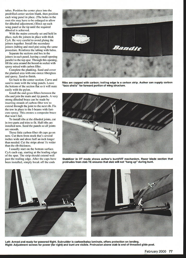
Wind the timer and connect the power, bunt, and rudder lines. Lock out the bunt. The glide/DT line is now connected. This configuration sets up a "power up and quick, safe DT" mode. The engine is run at full power for no more than 2.5 seconds. This will allow the model to gain enough speed and altitude to observe what it wants to do.
If it tends to loop, adjust by turning the power setting screw in (give it some "down elevator"). One-half turn at a time is usually safe. If the model wants to nose over, it needs "up elevator," so turn the screw out.
Increase the engine run by one-second intervals after the model is adjusted to climb straight up. Rotation to the right is okay, but any tendency to roll over must be corrected with rudder and/or incidence. The best pattern is vertical, with a half-turn to the right at the top. This will help initiate a downwind transition.
Be patient and stick with one adjustment at a time. It doesn't pay to rush the trim process, so take your time.
One very important factor in all of this is your launch form. This model will go where you point it—and that should be straight up.
Final Exam
The power pattern is dialed in, so try some short glide tests—30 seconds or so. Increase flight time as you fine-tune the glide.
Always remember to wind the timer fully and double-check the VIT lines before each flight.
You concentrate on that vertical launch, and your model climbs out "on a rail," snaps over to glide when the engine cuts, and makes big, slow circles before the turn tightens in lift. Two minutes and 15 seconds later, it DTs: perfect max!
Sources
Fuselage Systems: Ken Oliver 2213 El Cejo Cir. Rancho Cordova CA 95670 (916) 363-2017
Composite Material: Composite Structures Technology Box 622 Tehachapi CA 93581
Seelig Timers: Doug Galbreath 3408 Topasail Pl. Davis CA 95616
VIT Systems: (Also front ends, plans for the Bandit, other competition models, and good stuff. Catalog $1.) Bill Lynch 2279 Auburn Ravine Dr. Lincoln CA 95648 (916) 645-3337
Transcribed from original scans by AI. Minor OCR errors may remain.

