

Findings of electric Old-Timer conversions
Red Scholefield | [email protected]
I hope you will indulge me as I address a couple of non-battery/charger topics.
In the September column, I lamented an Old-Timer free-flight (FF) conversion's squirrely performance and the flutter problem in a powered sailplane. Maybe I can stretch it and claim that getting a model to behave correctly falls under the topic of safety. So, with apologies to MA's "Safety Comes First" columnist Dave Gee, I will share some letters from readers.
Kerswap comments begin with Will Greenwood of Warner Robins, Georgia:
"It appears to me that you are trying to fly a competition free-flight aircraft outside of the limits of its design.
"The Kerswap was designed to maximize a 15-second powered climb, in right turns, shut off the motor, and glide as long as allowed by the rules. A spiral climb was found to be much more stable than a straight climb. Therefore, the spiral slipstream from the propeller was directed to strike the left side of the pylon and force the aircraft to spiral to the right.
"The high wing and rearward center of gravity made the plane try to loop, while the pylon effect added an upward, right spiral. This combination turned the 'loop' into a climbing corkscrew path of about one-and-a-half turns before the motor stopped. The vertical stabilizer, which was tiny by today's standards, allowed the tail of the airplane to 'skid' to the right which kept the nose pointed upward during the climb.
"My own successes in converting competition free flights to RC required enlarging the vertical stabilizer (some modelers call it a 'rudder') and switching rudder rates on the transmitter. Some of these planes required some left rudder during takeoff. All my high-pylon planes required full-throttle takeoffs. Gradual takeoffs frequently resulted in ground loops."
Jack Albrecht added:
"You probably are aware that the SAM R/C assist flyers have been flying them for quite some time. I have been flying a 630-square-inch wing-area Lanzo Bomber for over 20 years in the SAM Limited Motor Run event as well as the Texaco event.
"The same old Bomber now uses a Hacker B40 10L +4.4 gearbox swinging a 15x8E APC propeller and the same 800 mAh pack. Climb is straight up."
Another Old-Timer, Kenneth Spittler, has also been adding electric to some of his vintage FF models, but only after fairly extensive modifications such as moving the wing pylon back and increasing fin and rudder areas. Recent test flights at our club with an electrified Zipper by Lyman Slack showed the same twitchy tendency as the Kerswap did. Thanks also to replies from Robert Hoey, Alex Zobell, and John Juechter, who sent pictures of their conversions — it appears that Old-Timer FF is alive and well, as electric power and radio-control (assist) enable them to be flown in more restrictive areas.
Howard Chapman wrote in about the flutter issue:
"Of all the variables that can lead to the problem I'll only get into what probably applies to your powered glider. Many years ago we had 12 to 15 Ugly Sticks at the Sepulveda Basin field. All flew with no problems in spite of poor building and poor equipment/linkage setups in many.
"Then they came out with MonoKote-covered Sticks instead of the normal silk/silkspan with dope. These had aileron flutter caused by the plastic covering being stretchy which changed the torsional resistance of the wing. One ugly cure used strapping tape in a diagonal crisscross pattern. The other went old school and mass balanced the ailerons with lead weights.
"Many big-plane engineers did that way back when and it's still the best cure I have seen over the years; either of these cures works the same way. They change the vibration modulus so the aileron flap speed does not get into a harmonic with the wing's rotational spring rate. Mass balance doesn't have to be absolute—just enough to disrupt the modulus match causing the problem.
"One of my friend's pattern ships was a flapper. When building the second one of the same I suggested top-mounting the hinges instead of following the kit's center-mount instructions. The second model didn't flap and the hinge change didn't affect the flying."
Jack Page addresses lithium use in transmitters. He wrote:
"I have noticed a trend among some of our fliers to replace their transmitter and airborne Ni-Cd packs with Li-Polys, obviously for the additional power and flight time possible. I think this is a mistake.
"To my knowledge, none of our radios have voltage-limiting circuits which will prevent the Li-Poly pack from over-discharging. This can ruin the pack and possibly damage the equipment."
The information in the September issue regarding spark suppression has some caveats. "DustyIV" posted the following on the RCGroups forum:
"What happens here is the Castle Creations ESC by default is set to automatically count the number of Li-Poly cells. If a resistor is added on the input to slowly charge the caps, the auto-detect will grab a count before the charge is complete.
"So let's say you are using a 4-cell pack. The auto-detect may think it's a 3-cell. You can take off and everything seems fine. Then it shuts the motor off thinking the voltage is pulled low.
"I checked with Castle Creations and this is their response: 'We recommend a 1 ohm 5 W resistor with our ESCs. A higher resistance rating can cause issues with the auto-Lipo detection.'"
For those interested, there is a long thread on the subject. See the Sources listing for where to find it.
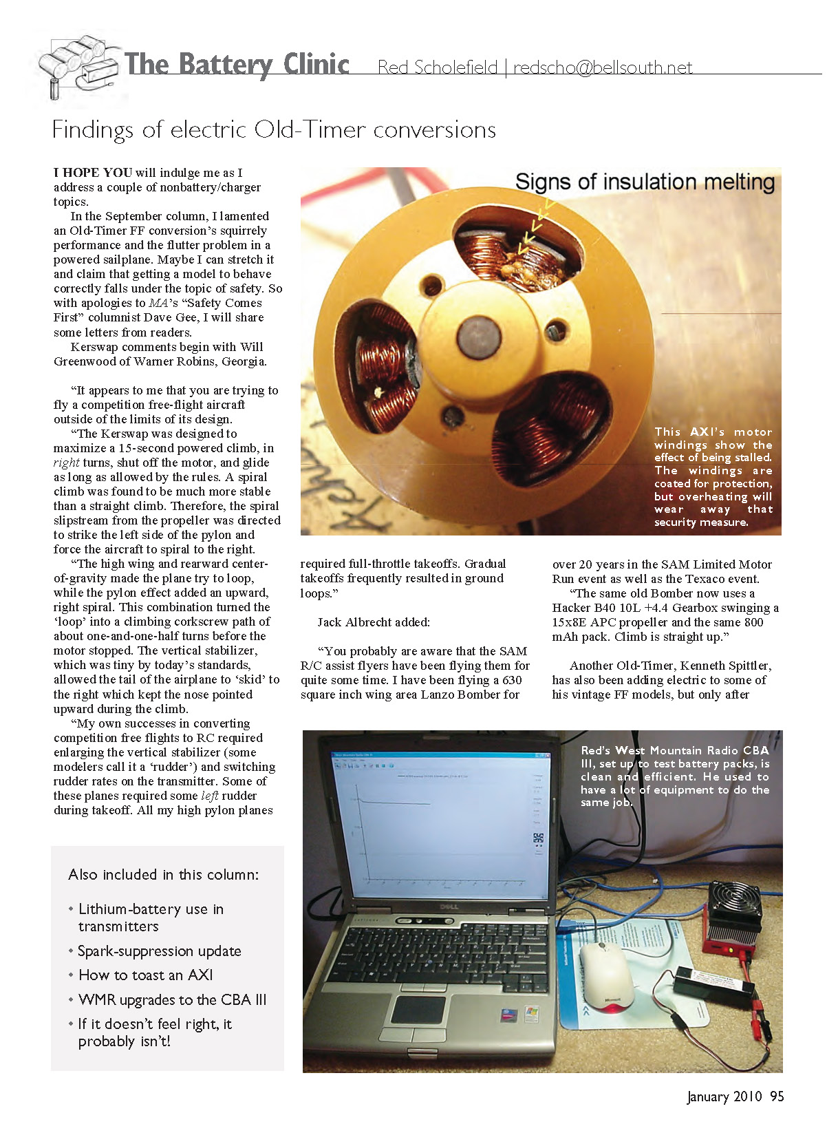
Toasting an AXI
I have been a strong proponent of AXI motors since they became available. I have never found one to fail. But you can make it happen if you want to badly enough.
Leave the throttle up a bit if you make a forced landing in high grass. Some ESCs have a cutout, but under the right circumstances it doesn't happen before the stalled motor is damaged. You can see the results in an accompanying photo.
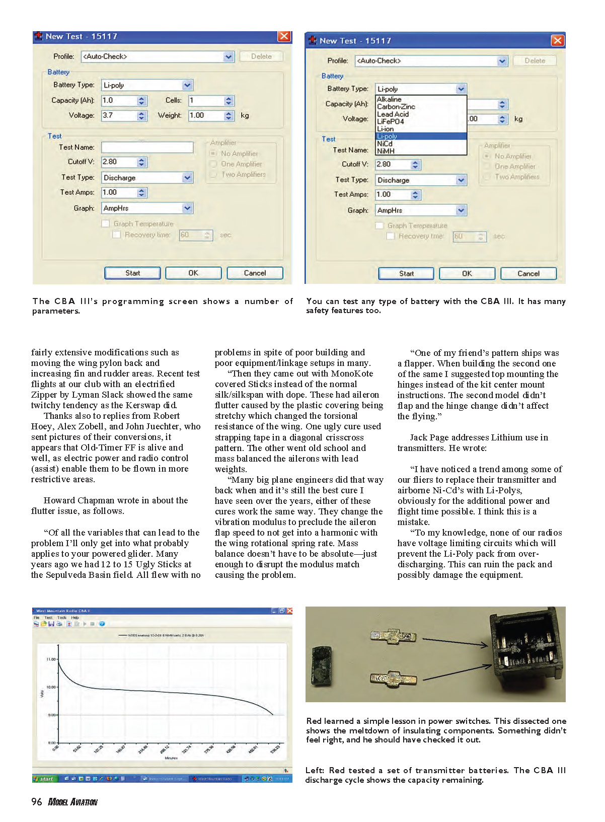
West Mountain Radio's original CBA II (Computerized Battery Analyzer) established itself as one of the best battery-test devices in the hobby. Now it has been replaced with the CBA III (consumer version: $149.95), which has significant new features and a software update to Version 2.1 (which works on all CBA units).
As with earlier models, the CBA III works in conjunction with your computer, plugging into a USB port where it is set up with a program from the provided CD. It covers all battery types that aeromodelers use and allows you to set the discharge parameters. Check out the photos of the setup options and the battery types served.
The CD supplied with the CBA III contains Microsoft Windows WHQL-certified drivers for Windows 98SE, XP, Vista 32, and Vista 64. It is also tested and ready for Windows 7.
Calibration has been tightened to typically ±0.5% from 0.5 to 40 amps and ±0.5% throughout the voltage range. Maximum testing voltage increased to 55 V, with voltage ranges of 0–5 V, 5–15 V, and 15–60 V. The wire pigtail on the earlier CBA has been replaced with Anderson Powerpole connectors.
Dual FETs lower the internal resistance, allowing regulation of more than 30 amps down to 0.9 volt for nickel-cell discharges. They also make it much easier to test heavier discharge rates for Li-Poly and other batteries. An on-board shunt measures current and reports to the software. The new design also makes it more difficult to burn out from reverse polarity or loose connections and lowers operating temperatures for better reliability.
The CBA gives you a clear and concise story of your batteries' performance. I upgraded my transmitter to one of the new packs made with Sanyo Eneloop cells. I wanted to see how much flying time I had after my morning at the field—mostly thermal hunting with my converted Bird of Time.
I ran a discharge with the CBA III, programmed to show minutes rather than amp-hours, and set for what my transmitter current drain would be. After more than an hour of flying, I still had plenty of capacity. After a few sessions with a CBA III, you won't have to wonder how close you are to the edge with your battery packs.
Bonus: this would make a great gift for the aeromodeler in your life.
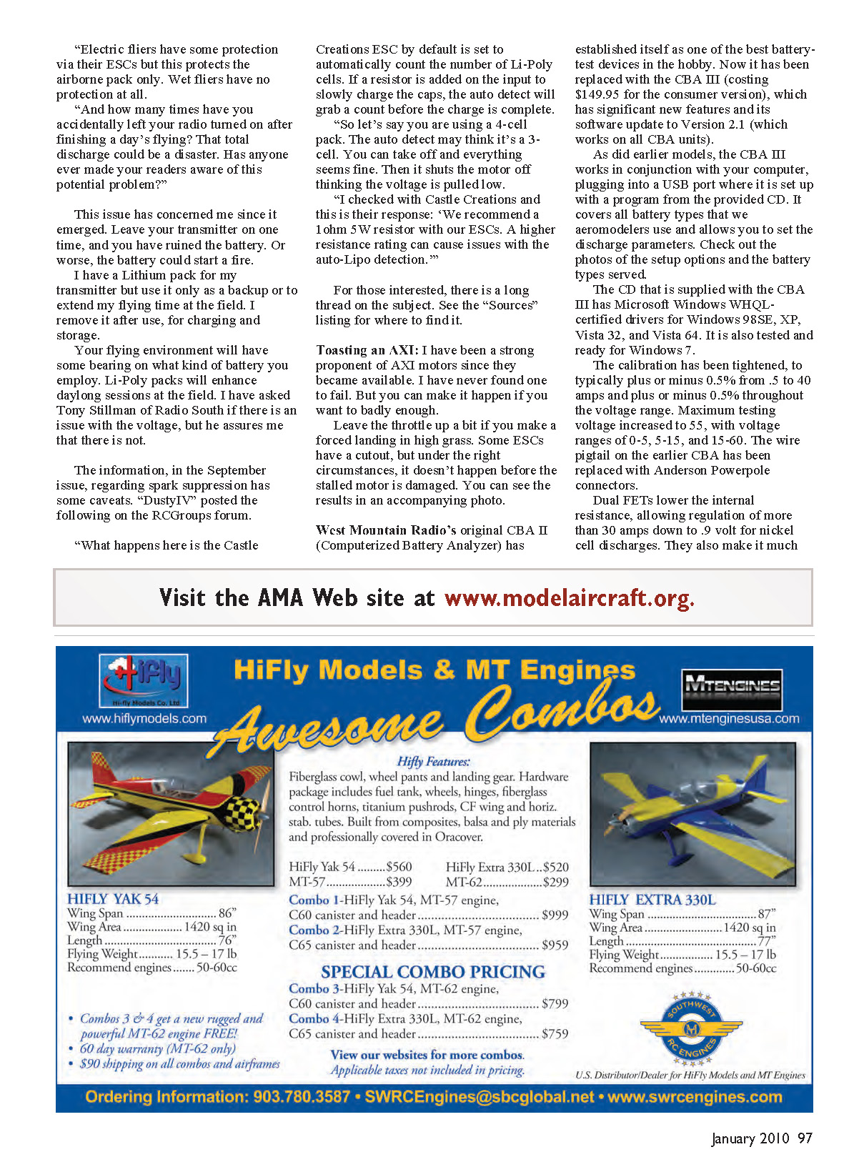
I use a double-pole toggle switch for my main power on electrics, wiring across both sets of poles in parallel. After many flights, I noticed that the switch didn't feel right. But since it was in one of my clunkers, I flew anyway, only to lose power immediately after takeoff.
When I retrieved the model, I couldn't turn the switch to the off position and found that one of the solder connections had melted from the switch. In the following autopsy, I learned that the plastic bar that toggles the contacts had given up, making a high-resistance contact and resulting in overheating at the switch contacts. In an accompanying photo, look at the two metal contact trips removed from the switch housing and the deformed plastic toggle at the left.
If it doesn't feel right, it probably isn't!
Thanks for the e-mails and letters addressing my "problems." I hope I have solved some of yours in the meantime.
Please note that I have canceled my membership at RC Universe. If you have battery questions, I do monitor the battery and charger forum on RCGroups.
Sources:
- Jack Page
- Spark-suppression discussion:
www.rcgroups.com/forums/showthread.php?t=1090782
- RC Groups' battery and charger forum:
www.rcgroups.com/batteries-and-chargers-129
- Red Scholefield at the Battery Clinic
12219 NW 9th Ln. Newberry FL 32669 www.hangtimes.com/redsbatteryclinic.html
Transcribed from original scans by AI. Minor OCR errors may remain.

