
The Battery Clinic — January 2006
An inside peek at a Li-Poly battery pack
Disassembly and observations
In the September column I looked inside a laptop-computer Lithium pack to marvel at the complexity of the circuitry it contained. Did you ever wonder what the inside of a Li-Poly pack looked like?
These exploratory excursions should only be attempted by trained professionals and not tried at home. No healthy cells were sacrificed in this examination.
I had a "violated" (propeller strike—don't ask) 900 mAh, 3S pack. I removed the violated cell and made it into a 2S pack that checked out to spec. Not wanting to waste an opportunity, I proceeded with an autopsy.
I started by discharging to 0 V at approximately 100 mA. It had been several days since the pack had been cut in a crash, so there was only roughly 20 mA left in the pack. The sweet smell you get with ruptured packs had almost gone away also.
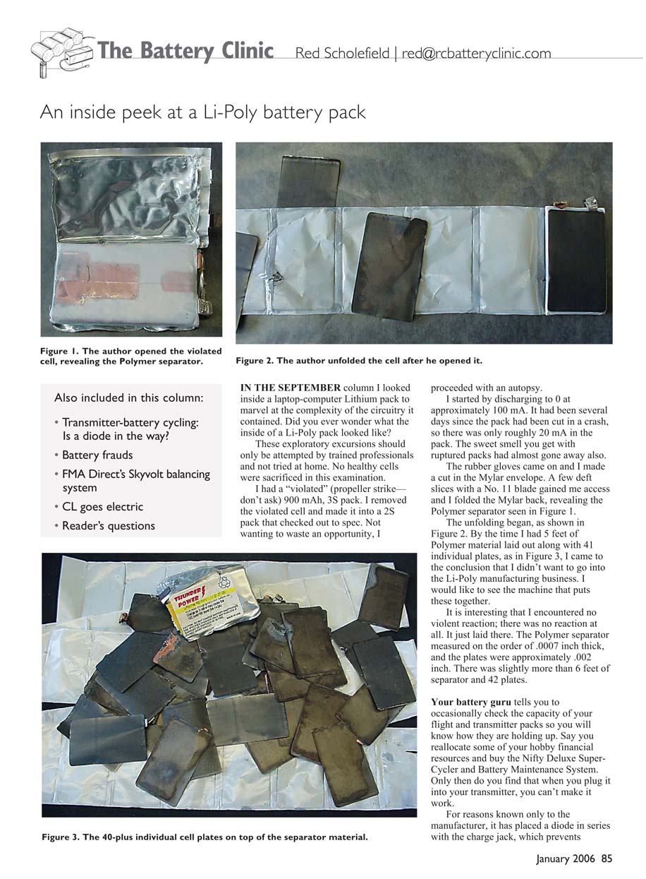
The rubber gloves came on and I made a cut in the Mylar envelope. A few deft slices with a No. 11 blade gained me access and I folded the Mylar back, revealing the polymer separator.
The unfolding began. By the time I had material laid out I came to the conclusion that I didn't want to go into the Li-Poly manufacturing business. I would like to see the machine that puts these together.
It is interesting that I encountered no violent reaction; there was no reaction at all. It just laid there.
Measurements and counts:
- Polymer separator thickness: ~0.0007 inch
- Plate thickness: ~0.002 inch
- Separator length: slightly more than 6 feet
- Number of plates: 42
Transmitter charge jack diode workaround
Your battery guru tells you to occasionally check the capacity of your flight and transmitter packs so you will know how they are holding up. Say you reallocate some of your hobby financial resources and buy the Nifty Deluxe Super-Cycler and Battery Maintenance System. Only then do you find that when you plug it into your transmitter, you can't make it work.
For reasons known only to the manufacturer, they have placed a diode in series with the charge jack, which prevents the cycler from discharging the pack through the charge jack.
For those little white connectors on the battery pack, a male Deans mini or JST plug is a solution. I recommend bypassing the diode with a single strand of servo wire. This will allow you to discharge the pack through the charge jack while providing short protection as a fuse; a single strand will handle no more than 2 amps. You can find details about performing this operation at the Peak Electronics Web site at www.siriuselectronics.com/. Click on "Diode Sheets." If you are not handy with a soldering iron, get someone who is to do the work for you. Making the modification may void your warranty; some manufacturers are put off by modelers trying to "improve" their equipment.
Battery fakes
A modeling friend was proud of the purchase he made: a package of 24 Duracell AA cells for $4. This was a great deal, with the best price for alkaline AA cells at 50¢ each. Then I noticed something strange about the cells; you could deform them just by squeezing. Then I looked closer at the name and it was "Dinacell"—not Duracell—but the packaging was nearly identical. Even Duracell's Bethel, Connecticut, address was replicated.
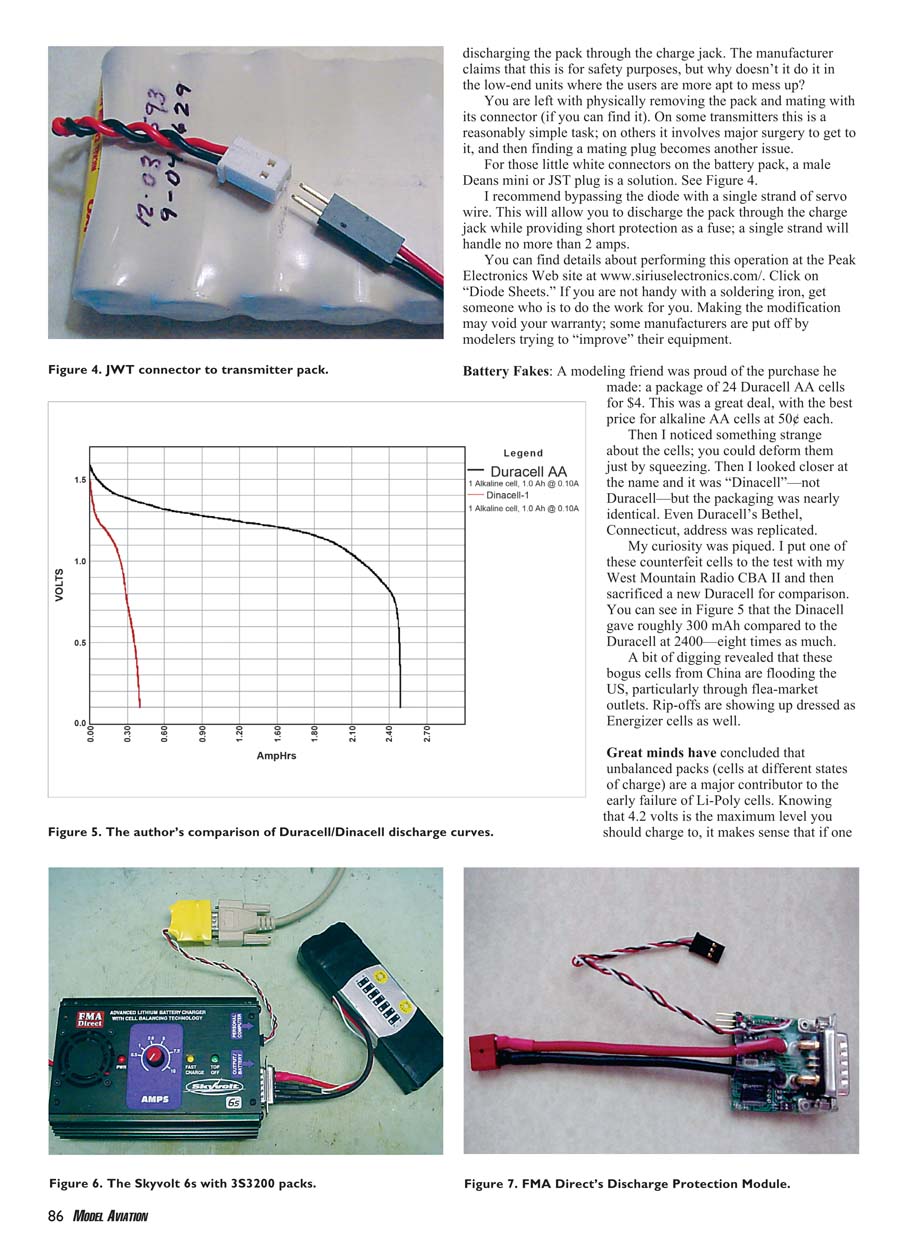
My curiosity was piqued. I put one of these counterfeit cells to the test with my West Mountain Radio CBA II and then sacrificed a new Duracell for comparison. The Dinacell gave roughly 300 mAh compared to the Duracell at 2400 mAh—about one-eighth the capacity. A bit of digging revealed that these bogus cells from China are flooding the U.S., particularly through flea-market outlets. Rip-offs are showing up dressed as Energizer cells as well.
Cell balancing and pack life
Great minds have concluded that unbalanced packs (cells at different states of charge) are a major contributor to the early failure of Li-Poly cells. Knowing that 4.2 volts is the maximum level you should charge to, it makes sense that if one cell in the pack is allowed to reach 4.2 volts before the others, that cell will be stressed and its life shortened. Periodically checking pack capacity and balancing the cells will prolong pack life.
Recommendations:
- Use a charger that provides cell balancing or use an external balance board.
- Consider discharge-protection or balancing hardware to prevent individual cells from being overcharged or overdischarged.
- If one cell is not coming up in voltage as fast as others, the good cells will have to go higher than 4.2 V to compensate. The more cells you have in series, the more critical the problem becomes.
Balancing chargers and the Skyvolt system
Lithium-pack distributors have come to our rescue with balancing chargers. The only way to balance cells in a pack is to have access to each cell. Any device claiming to balance the cells in a pack that does not have access to each cell is simply blowing in your ear.
Until now the procedure has simply been to provide taps to each cell and then, before charging, measure each cell voltage. If the cells are out of balance, charge them individually. There has to be a better way.
Several charger providers are offering balancing chargers to address the problem. I've had the opportunity to do some beta testing of the Skyvolt balancing system, offered by FMA Direct.
Skyvolt highlights:
- Targets larger-battery users — up to six cells in series at 2000–9600 mAh.
- 10-amp capability allows the cells to charge to ~90% capacity in about 20 minutes.
- All Skyvolt packs from FMA Direct come standard with the unique Safe Charge Connector, which is the power connector and the voltage-monitoring connector.
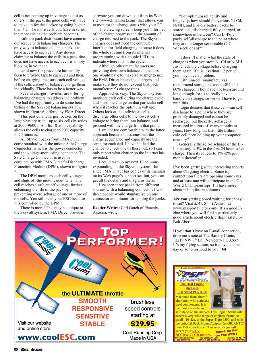
The Safe Charge Connector is used in conjunction with FMA Direct's Discharge Protection Module (DPM). The DPM monitors each cell voltage and shuts off the motor circuit when any cell reaches a safe cutoff voltage, further enhancing the life of the pack by preventing overdischarge of one or more cells. You still need your ESC because it is controlled by the DPM.
FMA Direct provides software you can download from its Web site (www.fmadirect.com) that allows you to monitor the charge status with your PC. The viewing screens keep you informed of the charge progress and the amount of charge returned to the pack. The Skyvolt charger does not need the computer interface for field charging because it does the whole routine from its internal programming with a couple of LEDs to indicate where it is in the cycle.
Although other manufacturers are providing their own balance connectors, one would have to make an adapter to use the FMA Direct balancing chargers and make sure they do not exceed that pack manufacturer's charge rates.
Approaches vary:
- The Skyvolt system monitors each cell during the charge cycle and stops charging that particular cell when it reaches the optimum voltage.
- Other systems look at the individual cells, discharge other cells down to the lowest cell voltage to bring them into balance, and then proceed with the charge.
I am not too comfortable with the latter approach because it assumes that the charge acceptance and capacity are the same for each cell. I have not had the chance to check one of these other systems, so I can only report what chatter on the Internet has revealed.
FMA Direct has copies of its manuals on its Web page's support section if you want more details and diagrams. I've seen three packs from different sources with a balancing connector. I wish these people would standardize on one connector and pinout for tapping the packs.
Reader question: Storage recommendations (Carl Gotch, Phoenix, AZ)
Question: For optimum reliability and longevity, how should the various Ni-Cd, NiMH, and Li-Poly battery packs be stored; i.e., discharged, fully charged, or somewhere in between? Can Li-Poly packs self-discharge to the point where they are no longer serviceable (2.7 volts/cell or so)?
Answers:
- Ni-Cd and NiMH: It doesn't matter what state of charge they are in when you store them. Just check the voltage before charging them again; if it is less than about 1.2 V per cell, you may have a problem.
- Li-Poly (Li-Ion): Manufacturers recommend storage between 40% and 60% charged. They have not been around long enough for definite long-term data, so we go with this recommendation.
Self-discharge and damage:
- Logic dictates these cells can self-discharge to a point where they are probably damaged and cannot be recharged, but the self-discharge is measured in many months to years.
- Generally, the self-discharge of Li-Ion batteries is about 5% in the first 24 hours after charge, then reduces to about 1%–2% per month thereafter.
Notes and resources
I've been getting some interesting reports about CL (control-line) going electric. Some top competition fliers are opening some eyes, and at least one will participate in the CL World Championships. I'll have more about this in future columns.
Are you getting bored waiting for epoxy to set? Visit MA's Sport Aviator at www.masportaviator.com/. It's a good e-zine where you will find a particularly good article about electric flight safety by Bob Aberle.
If you don't have an e-mail connection, drop me a note at: The Battery Clinic 12219 NW 9th Ln. Newberry, FL 32669
— MA
Transcribed from original scans by AI. Minor OCR errors may remain.

