
The case for standardizing Li-Poly balancers
Red Scholefield | [email protected]
Also included in this column:
- Using Windows hibernate functions with your chargers/cyclers
- Possible hazards in using power-tool chargers on hobby packs
- Checking new packs for reversed connectors
- The VoltMagic RC-system monitor
- The first realistic test data for battery-pack life cycle
THIS WILL BE a column of “do nots” and “be carefuls.” But when you are on the cutting edge, it is wise to exercise caution so you don’t get cut.
Do not use Microsoft Windows hibernate or sleep modes with your chargers/cyclers.
- In certain computers and versions of Windows the USB ports are disabled, ignored, or otherwise made inoperative when various power-saving features automatically activate. Disable those power-saving features if you are using your personal computer to control your chargers.
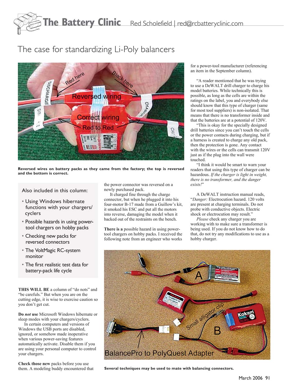
Check new packs before you use them.
- A modeling buddy discovered that the power connector was reversed on a newly purchased pack. It charged fine through the charge connector, but when he plugged it into his four-motor B-17 (made from a Guillow’s kit), it smoked his ESC and put all the motors into reverse, damaging the model when it backed out of the restraints on the bench. Always visually inspect and verify connectors before installation.
Hazards of using power-tool chargers on hobby packs
- There is a possible hazard in using power-tool chargers on hobby packs. I received the following note from an engineer who works for a power-tool manufacturer (referencing an item in a previous column):
“A reader mentioned that he was trying to use a DeWALT drill charger to charge his model batteries. While technically this is possible, as long as the cells are within the ratings on the label, you and everybody else should know that this type of charger (same for most tool suppliers) is non-isolated. That means that there is no transformer inside and that the batteries are at a potential of 120V.
“This is okay for the specially designed drill batteries since you can’t touch the cells or the power contacts during charging, but if a harness is created to charge any old pack, then the protection is gone. Any contact with the wires or the cells can transmit 120V just as if the plug into the wall were touched.
“I think it would be smart to warn your readers that using this type of charger can be hazardous. If the charger is light in weight, there is no transformer, and the danger exists!”
- A DeWALT instruction manual reads: “Danger: Electrocution hazard. 120 volts are present at charging terminals. Do not probe with conductive objects. Electric shock or electrocution may result.”
- Please check any charger you are working with to make sure a transformer is being used. If you do not know how to do that, do not attempt any modifications to use it as a hobby charger.
Balancing is good
- Balancing is important if you want to maximize service life. Nearly every lithium battery supplier is providing balancing taps, and many companies are releasing balancing devices. The bad news is that there seems to be a contest to see how many different connectors can be used. That makes each battery supplier’s product unique and incompatible with other balancing devices. If you have purchased an FMA Direct BalancePro system and want to use it with your PolyQuest pack, you may be out of luck. Until these vendors standardize connectors and pin-outs, we will have to apply our creative-modeling skills.
- Yes, the pack needs to be balanced if you want to maximize service life. That requires access to the positive and negative leads as well as the junction between the cells. Whether you have modified your pack with a balancing lead or have a pack with the balancing connector provided, you need a means to check each cell’s voltage and charge it if necessary.
Connecting and adapting balancing leads
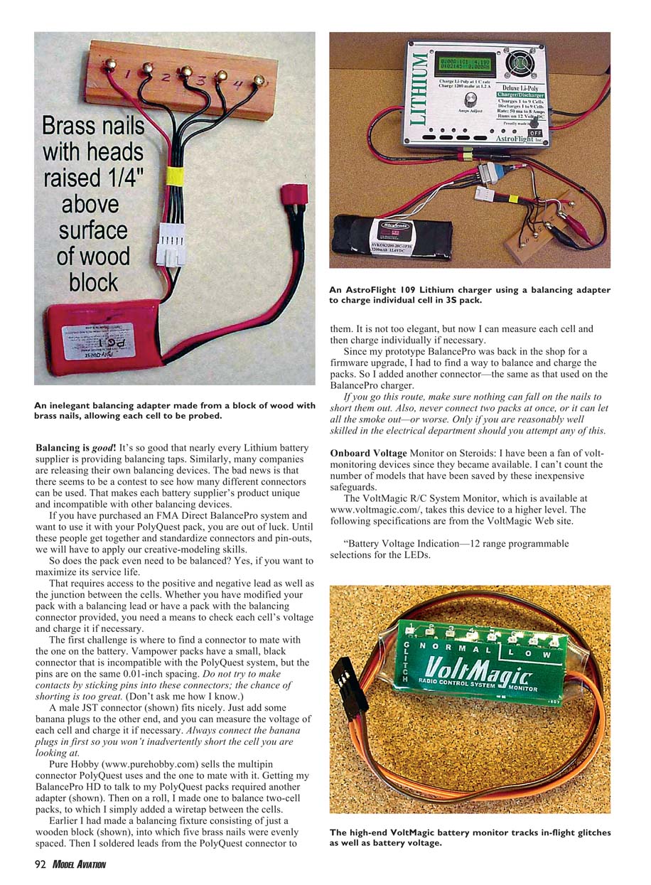
- The first challenge is finding a connector to mate with the one on the battery. Vampower packs have a small black connector that is incompatible with the PolyQuest system, but the pins are the same 0.1-inch spacing. Do not try to make contacts by sticking pins into these connectors; the chance of shorting is too great.
- A male JST connector fits nicely. Add banana plugs to the other end, and you can measure the voltage of each cell and charge it if necessary. Always connect the banana plugs first so you won’t inadvertently short the cell you are looking at.
- PureHobby (www.purehobby.com) sells the multipin connector PolyQuest uses and the mating connector. Getting my BalancePro HD to talk to my PolyQuest packs required another adapter. I also made one to balance two-cell packs by simply adding a wire tap between the cells.
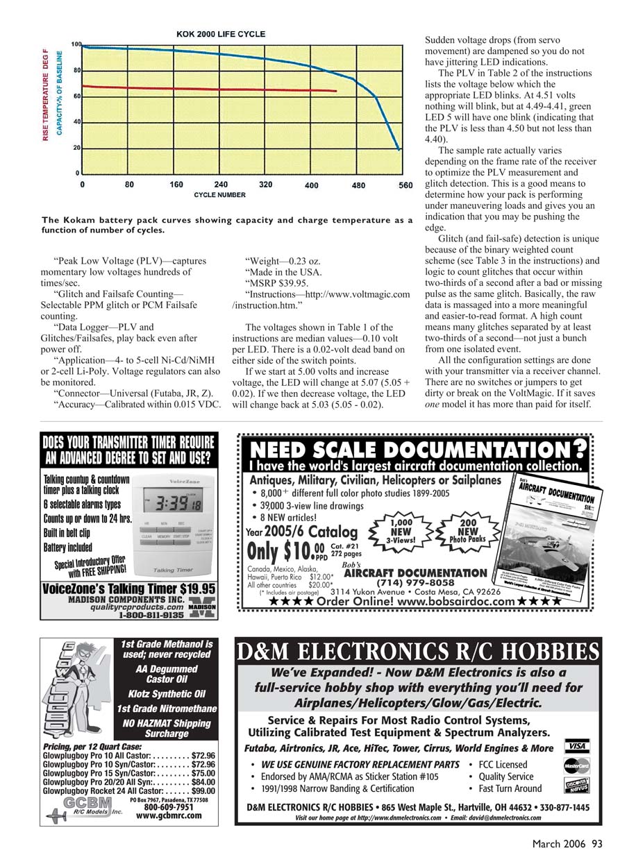
- Earlier I made a simple balancing fixture consisting of a wooden block with evenly spaced brass nails soldered to leads from the PolyQuest connector. It’s not elegant, but it lets me measure each cell and then charge individually if necessary. If you go this route, make sure nothing can fall on the nails to short them out. Also never connect two packs at once, or it can let all the smoke out—or worse. Only attempt this if you are reasonably skilled in electronics.
Onboard Voltage Monitor on Steroids: VoltMagic R/C System Monitor
- I have been a fan of volt-monitoring devices since they became available. I can’t count the number of models that have been saved by these inexpensive safeguards. The VoltMagic R/C System Monitor (www.voltmagic.com) takes this device to a higher level. The following specifications are from the VoltMagic website:
- Battery Voltage Indication — 12 range programmable selections for the LEDs.
- Peak Low Voltage (PLV) — captures momentary low voltages hundreds of times/sec.
- Glitch and Failsafe Counting — Selectable PPM glitch or PCM failsafe counting.
- Data Logger — PLV and Glitches/Failsafes, play back even after power off.
- Application — 4- to 5-cell Ni-Cd/NiMH or 2-cell Li-Poly. Voltage regulators can also be monitored.
- Connector — Universal (Futaba, JR, Z).
- Accuracy — Calibrated within 0.015 VDC.
- Weight — 0.23 oz.
- Made in the USA.
- MSRP — $39.95.
- Instructions — http://www.voltmagic.com/instruction.htm.
- The voltages shown in Table 1 of the instructions are median values — 0.10 volt per LED. There is a 0.02-volt dead band on either side of the switch points. For example, if we start at 5.00 volts and increase voltage, the LED will change at 5.07 (5.05 + 0.02). If we then decrease voltage, the LED will change back at 5.03 (5.05 - 0.02).
- Sudden voltage drops (from servo movement) are dampened so you do not have jittering LED indications.
- The PLV in Table 2 of the instructions lists the voltage below which the appropriate LED blinks. At 4.51 volts nothing will blink, but at 4.49–4.41 volts, green LED 5 will have one blink (indicating that the PLV is less than 4.50 but not less than 4.40).
- The sample rate actually varies depending on the frame rate of the receiver to optimize PLV measurement and glitch detection. This is a good means to determine how your pack is performing under maneuvering loads and gives you an indication that you may be pushing the edge.
- Glitch (and failsafe) detection is unique because of the binary-weighted count scheme (see Table 3 in the instructions) and logic to count glitches that occur within two-thirds of a second after a bad or missing pulse as the same glitch. Basically, the raw data is massaged into a more meaningful and easier-to-read format. A high count means many glitches separated by at least two-thirds of a second — not just a bunch from one isolated event.
- All configuration settings are done with your transmitter via a receiver channel. There are no switches or jumpers to get dirty or break on the VoltMagic. If it saves one model it has more than paid for itself.
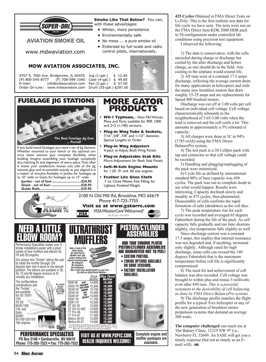
Cycles Obtained in FMA Direct Tests on Li-Poly
This is the first realistic test data for life cycle we have seen. The tests were run on the FMA Direct item KOK 2000 HDR pack in 3S configuration under controlled lab conditions using precision test equipment.
I observed the following:
- The data is conservative. The cells were uncooled during charge and discharge but were cooled by fan after discharge and before charge, as one should do in the field. Any additional cooling in the airplane would extend life.
- All runs were at a constant 17.5 amps discharge, reflecting the average current drain for many applications in helicopters and with the many new brushless motors that draw roughly 15–25 amps and replace Speed 400 brushed motors.
- Discharge was cut off at 3.00 volts per cell based on individual cell voltage. Cell voltage characteristically rebounds to the neighborhood of 3.65–3.80 volts when the load is removed and the cell cools a bit. This amounts to approximately a 5% rebound of capacity.
- All charges were done at 3C to 94% (1,785 mAh) using the FMA Direct BalancePro system.
- The test pack is a 3S Cellprop pack with tap and connector so that cell voltage could be recorded.
- Handling and plugging/unplugging of the pack were minimized.
- Cycle life as defined by international standard (80% of base capacity) was 450 cycles. The pack was run to complete death to see what would happen. Results were interesting: capacity total dropped slowly and steadily to 475 cycles, then plummeted. Disassembly of cells confirms the rapid formation of salts (dendrites) as the cell dies.
- The peak temperature rise for each cell averaged 65°F during the life of the pack. As cell capacity falls gradually and run time shortens slightly, the rise temperature falls slightly as well.
- Since discharge current was a constant 17.5 amps, this implies that internal resistance was not degraded and, if anything, increased only slightly. Although rated for high discharge, some cells can exceed the 140°F maximum temperature before cell life is significantly compromised.
- The need for and achievement of cell balance was also recorded. Cell voltage was brought to within ±5 millivolts even after 450 runs. This is a powerful testament to the desirability of cell balancing as done by FMA Direct BalancePro systems.
- The discharge profile matches the flight profile for a typical Trex helicopter or any of the new generation of brushless-motor propulsion systems that demand an average 200 watts.
The computer-challenged can reach me at The Battery Clinic, 12219 NW 9th Ln., Newberry FL 32669. An SASE will get you a timely response (but not as timely as an e-mail will). MA
Transcribed from original scans by AI. Minor OCR errors may remain.

